1
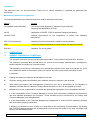
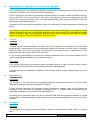
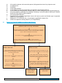
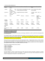
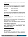
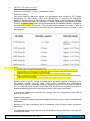
GPD 3 Tersus methods for Identification of asbestos in materials analysis by polarised light microscopy. LABORATORY PROCEDURE DOCUMENT, ASBESTOS IN MATERIALS March 12 Issue 1.0October Issue 8 Contents Copy number: Issued to: Introduction 1.0 LABORATORY (permanent) General conditions Layout Maintenance Security 2.0 STANDARD TEST PROCEDURES Identification of asbestos in bulk materials 3.0 QUALITY CONTROL Samples not containing asbestos RI liquids 4.0 EMERGENCY PROCEDURES Issued by: Tersus GPD 3: laboratory procedure document, Issue 8 March 12 1 of 19 Introduction This document sets out the procedures Tersus use to identify asbestos in materials by polarised light microscopy. Methods and adherence to regulations The following publications and methods have been used to draft these procedures. Method Purpose The analysts Guide (HSG248) The Analyst Guide Appendix 2: Asbestos in bulk materials. Sampling and identification by PLM. Lab 30 Application of ISO/IEC 17025 for asbestos sampling and testing. ISO/IEC 17025 General requirements for the competence of testing and calibration laboratories. GPD 3 (This document) Laboratory Procedure Document, Asbestos in bulk materials. CAR Control of Asbestos Regulations (current version, and supporting ACoP) HSG 264 Asbestos: The survey guide. 1.0 LABORATORY 1.1 GENERAL LABORATORY CONDITIONS The analytical laboratory occupies a designated area within Tersus offices at all head office locations. The laboratory premises also provide areas for secure record storage, administration, management, welfare facilities and writing up of reports/results. The laboratory environment is maintained in an appropriate condition for the tests to be carried out, so as not to affect the results of the analysis, and not to impose any risks to the health and safety of staff. In particular: a) Lighting and heating is adequate and suitable for the task. b) Sufficient working space and facilities (fume cabinets, benches, chairs etc.) are provided. c) Safe working procedures and arrangements contained in the ‘list of precautions for the handling of asbestos and other fibrous materials’, Quality Manual Sections, 19 and 23 are applied by all staff. d) Maintained so cross contamination is avoided and appropriate segregation of non-compatible activities. It is the responsibility of the Technical Manager to ensure that environment conditions are satisfactory and that standard procedures are followed. These conditions will be monitored by the Quality and Technical Managers, and delegated staff. It is the responsibility of the Technical Manager/top management to ensure that the laboratory building and services are properly maintained. If building or maintenance work is likely to be prejudicial to the functioning of the laboratory, the Quality and Technical Managers shall make arrangements to ensure that the quality of the work and health and safety is not adversely affected. Tersus GPD 3: laboratory procedure document, Issue 8, March12 2 of 19 1.2 MAINTENANCE OF LABORATORY CONDITIONS & EQUIPMENT It is the responsibility of the laboratory manager to maintain the cleanliness and good working order of all necessary equipment and environment within the laboratory. If the environment is such that it may adversely affect the quality of results or Health and Safety, tests will not be performed. If the environment is such that it may adversely affect the measurement the staff member will not carry out these tests. All authorised laboratory staff carrying out Bulk ID tests are authorised to make these decisions. A schedule will be kept within the laboratory to aid in the undertaking of routine maintenance, cleaning and testing. Any change in the location of the testing laboratory shall be planned accordingly by top management. UKAS shall be informed of any plans at the earliest opportunity and a system audit of the new laboratory location shall be undertaken asap. Top management shall also decide on the measures to be taken for handling equipment, samples, air tests of the laboratory environments etc. 1.3 TESTING Laboratory A regular air test on approximately a monthly basis will be carried out in the laboratory by authorised analytical staff. Results above the current clearance indicator of 0.010f/ml of air shall result in immediate corrective action. As current law requires accreditation for fibre discrimination, an assessment of fibre types observed in any counts shall not be carried out. In any event we shall attempt to minimise the release of asbestos fibres to the lowest possible level by good housekeeping and regular fume cupboard service etc. Fume Hood Face velocity tests using an anemometer will be undertaken weekly, to make sure face velocity is above the minimum of 0.5m/s this will be undertaken by competent laboratory staff. A smoke test may be undertaken in addition to face velocity tests to visually assess leaks in the fume cabinets. 1.4 MAINTENANCE Fume hood The pre filters to the fume hood will be replaced based the manufactures guidance. The main HEPA filters will be changed under the manufactures guidance. If filters become excessively dirty between routine maintenance changes, filters will be changed as necessary. Filters will either be changed by laboratory and / or technical staff as instructed by the manufactures guidance or by manufactures representatives. Air testing will be undertaken within the lab by authorised staff after filter changes in addition to regular testing regime. DOPS testing will be undertaken as per the manufactures guidance, this is on a 6 monthly program. 1.5 CLEANING Laboratory The laboratory is thoroughly cleaned and tidied in relation to non asbestos related waste on a regular basis. Tersus GPD 3: laboratory procedure document, Issue 8, March12 3 of 19 Fume Hood The fume hood will be visually inspected at the end of each shift, prior to being turned off and cleaned as necessary. Any obvious debris must be cleaned before the fume hood is shut down. Cleanliness of all equipment stored or used in the fume cupboards must be maintained at all times to stop cross contamination during analytical work. A full clean of each individual fume cupboard that has been used that day will be undertaken at the end of the working day using procedures as documented in the asbestos essentials task manual, page 24. The following procedure is adopted: Vacuum (H-Type) any bulk debris Use wet wipe or soaked tissues to wipe all surfaces, refold to clean surface if necessary Dispose of cloth, do not re use. Repeat until all surfaces have been cleaned If using tape, place over contaminated surface and remove slowly Tape is only appropriate for small dust deposits. Equipment All cleaning of analytical equipment and instruments is done by laboratory personnel after each use to prevent cross contamination. The Laboratory manager (Quality and Technical managers to deputise in lab managers absence) and delegated staff are responsible for ensuring that the analytical area is kept clean and tidy. Where used lab coats will be laundered when dirty by a laundering service. Lab coats that have been contaminated by accidental asbestos spillage will be disposed of as asbestos waste. Correct solvents will be used to clean bitumen and or any other resistant materials from equipment. Serrated tweezers are NOT to be used, as these cannot be effectively cleaned. Waste All analysed samples will be double bagged within sample bags and then placed in a red asbestos waste bag within the designated storage bins in the lab and other storage areas. Customer submitted bulks and survey generated bulks will be separated into their relevant groups and bagged as waste. This is so samples can be archived in a more effective manner. General asbestos waste derived from the laboratory operations is placed in a separate clearly marked designated storage bins and double bagged and disposed of as asbestos waste as necessary. All asbestos waste bags will be sealed and double bagged as asbestos waste on a monthly basis; all sealed bags will be stored in the lockable store cupboard. Samples will be kept for 6 months. 1.6 SECURITY OF LABORATORY PREMISES The premises will be securely locked when staff are not on site. An electronic alarm system is armed when the offices are left unoccupied at the end of each working shift. Out of normal hours Out of hours work within the laboratory will be undertaken only when authorised by the Technical Manager. An assessment from a safety and security point of view for lone workers must be undertaken by top management prior to authorising out of hours work. Tersus GPD 3: laboratory procedure document, Issue 8, March12 4 of 19 2.0 STANDARD TEST PROCEDURES 2.1 ENQUIRIES, RECEPTION AND REGISTRATION OF SAMPLES Enquiries are normally dealt with by designated trained personnel. Bulk samples for fibre identification are received in Reception by Tersus staff as appropriate. Samples may be delivered by hand, received by post, or brought into the laboratory by our own staff taken during sampling work. Sample details are entered onto the Tersus database by authorised staff. The database either retains the unique identification generated by survey staff, or allocates a unique identifier in addition to that provided by the customer. In any case the unique ID will be clearly marked on the sample itself. These are usually retained in transparent bags, on or through which the unique ID shall be clearly visible. The mechanism for generating the samples unique ID are detailed in Tersus database user manual. Additional identifiers allocated by the customer may be added into the ‘comments’ part of the bulk report, as required, by analytical staff. All samples submitted, or any posted mail bags suspected of containing samples*, are only opened within the fume cupboards. These may require additional bags to ensure that all samples remain double bagged at least, unless within the fume cupboard. (*Any relevant paper work required for booking in samples will then be returned to the administration staff in a suitable clean or suitable sealed condition to protect administration staff from potential respirable fibres). Customers bringing in inappropriately packaged samples shall be asked to leave the sample outside of the building where they can be properly double bagged before being brought onto the premises. Samples will then be transported straight into a fume cupboard where the packaging is not suspected to be adequately sealed. All personnel involved in the collection and handling of test and inspection data shall ensure the confidentiality of this information and be aware of the necessity to protect proprietary rights. 2.2 STORAGE, PROTECTION AND DISPOSAL OF SAMPLES Bulk samples All bulk sample packages will be opened and assessed within a fume cupboard, and bagged in a clean outer sample bag these are then safe to be stored in the reception area ready to be booked in and stored awaiting analysis. Samples will be stored in dedicated area until allocated for analysis or collected by laboratory staff. Handling of samples for asbestos analysis taken by Tersus authorised staff on site are detailed in other technical procedural documents. All work on samples involving sample or fibres being exposed to the atmosphere will be conducted in the running fume cupboards. Bulk samples are, as necessary analysed as a whole or divided into sub samples, for example textured decorative coating and its substrate. Sub samples will be allocated a separate unique sample number and the sub sample status will be recorded within the comments field on the Tersus bulk analysis database screens. This is then printed on the bulk analysis report. All sub samples should be individually sealed in separate sample bags and double bagged as a whole sample in one outer bag, then grouped and bagged with the rest of the customer’s samples. Residual slurry and water from wet sieving, if used, will be bottled in a container with a screw cap, double bagged and disposed of as asbestos waste. Bulk samples, already sealed in polythene bags, are stored in a red polythene asbestos waste sacks. These are in turn put into clear asbestos waste bags ready to be sealed and stored. Tersus GPD 3: laboratory procedure document, Issue 8, March12 5 of 19 Prepared slides for polarised light microscopy are disposed of in a plastic container which is stored in the fume cupboards which, when full, these containers are sealed and disposed of as asbestos waste. When a red sack is full it is sealed and placed in a clear polythene sack, the record of which samples therein the sack being placed, facing outwards, between the inner and outer sacks. This sack is then sealed and kept ready for disposal in accordance with current waste regulations. If requested, samples may be stored for longer or returned to the commissioning authority. If bulk samples arrive at the laboratory with no instructions or customer contact, they are to be "sealed". They will be placed in sealed sample Box which is kept in the reception area cupboard or waste cupboard. The box will state "Sealed Samples- do not analyse until further instructions are received” or similar. 2.3 REFERENCE LABELLING OF TESTS/ITEMS RELATING TO THE QUALITY SYSTEM Allocation of Individual Employee/Analyst Identifier Number Employees will normally be allocated consecutive unique ID numbers by the Technical Manager. The analyst will be allocated a reference number within the company’s laboratory database. Any analysis within the company will have the analyst name assigned to that sample. The printed bulk reports will show the analysts name as has been assigned. 2.4 HANDLING PRECAUTIONS Refractive Index Liquids/Acetone/Triacetin These liquids are potentially harmful by inhalation and skin absorption. Instructions on safe handling and safety data sheets for all chemicals analysts use are made available during training for all staff involved in their use. a) b) c) d) e) f) g) i) Do not smoke, eat or drink when in use. Do not ingest or inhale these liquids. If liquid accidentally contacts the skin, wash off immediately with soap and water. Tighten bottle caps after use. Do not leave mounted slides on bench when work is completed. Immediately they are not required, place the slides in a covered box to minimise odour of the liquid. Full boxes are bagged and treated as asbestos waste, where unused and past use by date. Ensure the laboratory is well ventilated. Store bottles at room temperature. Bottles are clearly labelled and kept clean externally. RI liquid bottles should be stored outside of fume cupboards in a clean environment to minimise potential contamination of the liquid. Equipment; The basic equipment requirements for PLM analysis are as follows: RI liquids, glass slides, cover slips (no. 1 no less than 15mm diam), seeker, tweezers, tissues, wet wipes, fume cabinet with HEPA filter (conforming to BS7258) and Koehler type illumination PLM microscope. Other equipment employed as required are latex rubber disposal gloves, pestle and mortar, washable Petri dishes, ultrasonic bath, acetic acid and pliers. Before use of a microscope for polarised light microscopy/dispersion staining microscopy the following checks are made: i) ii) iii) iv) The polariser and analyzer are crossed and oriented NS and EW The sensitive tint functions correctly and is correctly oriented The phase rings, microscope illumination and condenser are correctly adjusted The Koehler (Koehler type) illumination microscope used must include the following: Tersus GPD 3: laboratory procedure document, Issue 8, March12 6 of 19 a) b) c) d) e) f) g) h) i) j) k) 2.5 A focusable condenser with numerical aperture (NA) greater than that of any objective used. A condenser iris. A polariser. A removable analyser. A removable first order red compensator (of retardation approximately 530 nm). A level rotating and independently centrable stage (or a level rotating stage and centrable objective). A focusing eyepiece (preferably non-rotatable) containing a cross-hair graticule defining the vibration directions of the polariser and the analyser. A focusing phase telescope. Eyepieces of 8 x or higher magnification (those with high eye points and flexible caps for spectacle wearers are advantageous). Objectives of 10 x (minimum NA = 0.2) and higher magnification (higher NA). A McCrone dispersion staining objective (10 x magnification). IDENTIFICATION OF ASBESTOS IN BULK MATERIALS Unpack samples in safety cabinet and carry out initial visual or preliminary stereo microscopy observations Describe sample as homogenous or non-homogeneous (describe each individual layer by colour, texture, and if possible, material type). Take sub-samples if necessary If necessary, remove interfering matrix materials which may hamper identification Conduct careful search of the sample under the stereo microscope using the tweezers, and probe to find and isolate fibres Fibres observed Fibres not seen Note individual fibre types by observing appearance and handling properties under the stereo microscope Consider further sample preparation to see if fibres are still embedded or encapsulated Make tentative identification of fibre types present Take small random samples and place each between two microscope slides and disperse by gentle grinding, then draw apart.+ Extract several fibres or fibre bundles of each type of asbestos and tease apart Place RI liquid on cover slip and invert onto slide and allow capillary action to immerse sample. Scan the sample at x 100 or greater* for fine fibres using PLM or PCM Mount in matching RI liquid for PLM identification (see Figure 2 for choice of liquid) If fibres observed prepare additional slides for PLM identification Tersus GPD 3: laboratory procedure document, Issue 8, March12 If no fibres observed report result 7 of 19 + . Note: Hard materials may scratch the slide or be too large to form a satisfactory mount, dispersing sub-samples in a liquid by shaking and waiting a few seconds for large particles to settle out before pippetting one or more drops onto a microscope slide and drying can also be used. * Note: Fine chrysotile fibres were commonly used in some commercial products (e.g. vinyl asbestos floor tiles and decorative / textured coatings). Fine asbestos fibres may also be present in some mineral products and settled dusts. Higher magnifications e.g. using X 500 phase contrast microscopy (PCM) optics may be used to search for fine asbestos fibres. Increased visibility and contrast can be obtained by using liquids with a large RI difference from the fibre (e.g. for chrysotile use water, or a liquid of RI = 1.67). The following method for identifying asbestos in bulk materials is used: Asbestos: The analysts’ Guide for sampling, analysis and clearance procedures HSG 248 (Appendix 2 Asbestos in bulk materials: Sampling and identification by polarised light microscopy). Sample treatment and preparation will be as described in the sub sections following. Identification will be by the methods described in Asbestos: The analysts’ Guide for sampling, analysis and clearance procedures. (Appendix 2 Asbestos in bulk materials: Sampling and identification by polarised light microscopy) HSG 248. With the following exceptions. i) The Becke line test will not normally be employed The analyst will handle all materials in such a way as to avoid cross contamination at all times. Only one sample will be worked on at any one time (along with corresponding paperwork), all other samples waiting for analyses will be suitable sealed and stored away from the working area to ensure results are only entered onto the correct corresponding paperwork. Disposable gloves will be worn at the analyst’s discretion. All samples will only be opened within the working fume hood. All sample analysis will start by being evaluated under low power stereo microscopy. All parts of the sample will be evaluated, some samples may have distinctive layers, and other samples will have other materials attached to them. These will be reported as sub samples. Sub sample will be booked into the laboratory’s database system as a new sample and the sub sample status of the material recorded within the comments field for that sample. This will then be printed on the bulk report. Principle A representative sample of the material thought to contain asbestos is collected for examination. In the analytical laboratory, this is examined by eye, followed by more detailed examination using a low power stereo-microscope. One or more representative sub-samples may be prepared mechanically and/or chemically for further examination Fibres observed in the course of these examinations are categorised tentatively on the basis of morphology and certain physical properties. Each fibre type so recognised is sampled by selecting a few fibres or bundles, and these are mounted in a refractive index (RI) liquid chosen to match the most likely asbestos type. The fibres then are positively identified as one of the six regulated asbestos types on the basis of their detailed optical properties using polarised light microscopy (PLM) with magnifications from about 80x upwards, as appropriate to the type of sample. 2.6 DETAILED ANALYTICAL PROCEDURES Initial examination The entire sample should be examined by eye to describe the type of material or product present, and to establish whether or not visible fibres are present. Tersus GPD 3: laboratory procedure document, Issue 8, March12 8 of 19 The natures of any binder materials should be noted, as they may influence treatment of the sample. Examination of insulation samples and many manufactured products under the stereo microscope will aid the detection of fibres and allow some initial assessment of the number of fibre types present. Certain products such as vinyl floor tiles, and settled dusts, may contain asbestos fibres that are too fine to be detected in this initial examination. The appearance, colour and texture of the sample, and any fibre types observed, should be recorded. For non-homogeneous samples, each separate layer, part or variant may require individual description. Sub samples will be booked in as a unique identifiable sample number, with the status of the sub sample being reported in the free text comments field of the database. Sample preparation and the analysis of the sample are dependent on the quality of the initial visual examination. Also, adequate description of the appearance of the sample is important in establishing where, or in which part, the asbestos material is present. Sample treatment The purpose of sample treatment is to release fibres from any matrix and to remove fine particles adhering to the fibres (both of which obscure optical effects and hinder identification). Non-friable samples will need to be broken (with tools if necessary) and the newly fractured edges inspected under the stereo microscope to reveal protruding fibres. Some hard pieces may require grinding. Surfaces and edges may be abraded to release fibres. The following reagents may be available for use in the laboratory:Acetic acid (glacial) Acetic acid (10%) White Spirit Methylated spirit Acetone Water Any deviations from these procedures for particular samples should be recorded. (Triacetin is stored within the laboratory for use in air testing it is not thought that triacetin will be used as a reagent in the bulk identification of asbestos containing materials.) Dilute acetic acid (e.g. 10%) may be used to remove calcium carbonate and calcium silicate. Sufficient acid should be added in small amounts for several minutes or until effervescence stops. Fibre release may be aided by stirring or by ultrasonic treatment. The sample may then require rinsing at the analysts discretion (acetone will be used to reduce drying time.) Organic binders (for example, in plastics, bitumen, resin or rubber products) may require prolonged treatment in solvents. An effective solvent for any single sample can only be established by trial and error Glacial acids should not be used for sample preparation and strong acids may affect the optical properties of the fibres being identified. Asbestos containing materials in soil samples Attempt to establish the type of contaminant/asbestos containing material and therefore likely morphology/product from customer supplied details. Search soil for material in fume cupboard or outside on drop sheet in accordance with controls defined in risk assessment. Ensure retention of entire sample. Where materials cannot be identified then we shall not undertake material analysis. The opinion on lack of material/product identified shall not be reported on media, or in text, which implies it has been done under the terms of our accreditation. Where material/product is identified then the steps in 2.5 shall be followed. Tersus GPD 3: laboratory procedure document, Issue 8, March12 9 of 19 Stereo microscopy The original samples or portions of sample that have undergone sample treatment should be examined using the stereo microscope. (The magnification used will be at the analyst discretion but all samples should be assessed using the full range of optical zoom available on the stereo microscope) The aim is to detect small fibre bundles, or individual fibres, and to assess the proportion of fibres present and tentatively assign fibre types based on their appearance. This is achieved by placing the sample in a Petri dish and performing a detailed search of the whole sample using fine point seekers and fine point tweezers to separate the different fibrous components from the matrix and recording their appearance on the analysis work sheet. Representative fibres or fibre bundles are then selected and mounted for PLM. All equipment used to prepare the sample should be cleaned prior to use or before direct handling of the material Rigid samples (such as a tiles, cement, plastics, resins etc) will be broken, the fractured edges inspected under the stereo microscope to reveal protruding fibres and the surfaces and edges may need to be scraped to aid in fibre release. Samples not having a homogenous mix or having a hard matrix will be broken, scraped and teased apart to ensure suitable examination of all cross and subsections. In each case other preparation methods and solvents may be necessary and it is at the at the analysts discretion which are to be used to ensure thorough preparation and material inspection. Textured coatings will be inspected and then powdered if necessary to try and release fibre types. (Further sample preparation with reagents may then be necessary) Layered samples should be described by their appearance and each sub sample noted as a separate entity. Other types of non-homogeneous samples will require detailed visual examination. If lagging is to be wet sieved, the material will be sub divided and one part wet sieved through a 425µm sieve, allowed to dry and assessed. The un-sieved half of the sample will be kept separate from the sieved half. Residual slurry and water from wet sieving will be bottled in a container with a screw cap, double bagged and disposed of as asbestos waste. All observations should be recorded. Initial tentative identification of the fibres at this stage will be confirmed or refuted by subsequent examination using PLM. Tersus GPD 3: laboratory procedure document, Issue 8, March12 10 of 19 Physical property/appearance Colourless/ Colour Colourless/White to Grey Brown White Greenishgrey Deep Blue Texture Soft with Soft or harsh; may appear as easily Soft or harsh with parallel bundles of visible parallel fibre bundles fibre bundles sinuous fibres Appearance Flexible fibres Straight fibres easy to handle which cling to tweezers Lustre Silky Vitreous Vitreous Vitreous Vitreous Metallic (dark and highly reflective) Tensile strength High High Medium Low Low High Tenacity Flexible Flexible Flexible Flexible Flexible Flexible Elasticity Inelastic Elastic Elastic Elastic Elastic Elastic Tentative asbestos type Chrysotile Amosite Anthophyllite Tremolite Actinolite Crocidolite 1.670 1.605 1.605 1.640 1.700 RI liquid for 1.550 test Straight fibres easy to handle Preparation of samples for PLM A tentative identification based on the stereo microscopy evaluation is used to select the most appropriate RI mounting liquid. The refractive index of the mounting liquid will be written onto the glass slide if more than one refractive index liquid is being used to identify a fibre type. The unique id of the sample shall be written on the slide to enable mount numbers to be cross checked in order to support in house qc procedures ie the completion of the ‘Daily RI liquid mount record’ spreadsheet. Fibres will be dry and relatively free from other particulate matter. Representative fibres or fibre bundles are chosen and are placed on a clean microscope slide into a drop of RI liquid, and a clean cover slip is lowered gently onto the slide. Only slides prepared in this way may be removed from the fume cupboard ie the suspected asbestos fibres are sealed by fluid and cover slip. The RI of the liquids used will be as follows:1.550 For Chrysotile 1.605 For Anthophyllite 1.605 For Tremolite 1.640 For Actinolite 1.670 For Amosite 1.700 For Crocidolite For bulk samples in which no fibres have been seen using the stereo microscope, tweezers or probes should be used to take two random sub-samples. At least two microscope slide preparations should be made with appropriate RI liquids for examination by PLM. Tersus GPD 3: laboratory procedure document, Issue 8, March12 11 of 19 The amount of sample distributed should be such that the appearance and properties of individual fibres are not obscured by other particles. Asbestos identification by PLM Identification of asbestos fibre will normally be conducted in the following order and the assessment of the following properties will be noted on the analysis work sheet. Morphology will be assessed and recorded in all modes Pleochroism will be assessed and recorded in plain polarised light (PPL) Birefringence will be assessed and recorded in crossed polars (XP) Extinction characteristics will be assessed and recorded in crossed polars (XP) Elongation will be recorded in crossed polars with 1st order red compensator (530µm) The microscope is set so that length slow (positive) fibres are blue in the NE – SW orientation All of the above will be conducted with the McCrone dispersion staining lens set to no stop McCrone dispersion staining assessment will be conducted in plain polarised light with the dispersion staining lens set to the central stop position. The sequence may be altered at the analyst’s discretion to aid in the determination of difficult to find fibres or assessments of non asbestos mounts so long as all properties are observed and recorded. Identification is based on comparing the recorded observations on the fibres selected for analysis (and mounted in the appropriate RI liquid) against the properties of asbestos reference standards. Further representative fibres will need to be analysed if the observations are inconclusive, or if more than one type of fibre was found in the stereo or PLM analysis.(see table). The result of “inconclusive” may be reported where the examinations do not provide a conclusive result. Where difficulties occur in distinguishing between Tremolite and Actinolite or between Tremolite and Anthophyllite, in such cases other methods of analysis (X-ray diffraction, Electron microscopy etc.) may be employed. These test services will be procured from UKAS accredited laboratories only and will only be undertaken with the express permission, and the cost covered by the customer. Where difficulties occur and no other appropriate test method can be procured (permissions or cost restraints of the customer) the laboratory will report the presence of amphibole asbestos fibres. (NB re following table: Fibre parallel or fibre perpendicular describes orientation with respect to the polariser. Dispersion colours relate to the HSE reference standards. Slight compositional variations will give rise to differences in the dispersion staining colours observed. RI ranges marked * were obtained from commercial asbestos fibre; RI ranges marked + were obtained from non-commercial fibres. Tersus GPD 3: laboratory procedure document, Issue 8, March12 12 of 19 Properties used to identify asbestos by PLM Asbestos type Chrysotile Amosite Anthophyllite Tremolite Actinolite Crocidolite RI liquid 1.550 1.670 .1605 1.605 1.640 1.700 Property Morphology Fibrous Fibrous Fibrous Fibrous Fibrous Fibrous Fibrous Pleochroism Fibre parallel None None None None Green Blue Fibre perpendicular None None None None Grey Grey Birefringence Low Moderate Moderate Moderate Moderate Low/anomalous Extinction Complete, or undulose with curved fibres; parallel Complete; parallel Complete; parallel Complete; parallel or small angle Complete; parallel or small angle Complete; parallel Sign of Usually positive (length slow) Positive (length slow) Positive (length slow) Positive (length slow) Positive (length slow) Usually negative (length fast) Purple Yellow Yellow- Yellow Yellow-brown Blue Blue Purple-red Blue-red Blue Blue-purple Blue Pale-blue Orange Grey Yellow Dark-grey Orange Dark-grey Yellow Dark-grey Yellow Blue Red-brown Pale-blue Orange Blue Orange Blue Orange-yellow Blue Orange Blue Orange Blue Red-brown n 1.537-1.554* 1.6700-1.675* 1.59601.654+ 1.599-1.620+ 1.619-1.658+ 1.680-1692* n 1.6830-1.694* 1.683-1.694* 1.625-1.667+ 1.622-1.641+ 1.641-1.677+ 1.683-1.700* elongation Dispersion Staining Objective Colours Phase Contrast Objective Colours Refractive Index Ranges Fibre parallel Fibre perpendicular Fibre parallel fibre colour halo colour Fibre perpendicular fibre colour halo colour Tersus GPD 3: laboratory procedure document, Issue 8, March 12 orange 13 of 19 2.7 INTERPRETATION OF ASBESTOS IDENTIFICATION BY PLM The fibres identified will be assessed for the following properties in a logical sequence. a) Morphology To detect small fibre bundles, or individual fibres, and assign fibre types based on their appearance. Asbestos is recognised by the fineness of fibres present in closely packed bundles of fibrils that will divide along their length when pressure is exerted on them. Other characteristics such as distinctive surface lustre, flexibility and tensile strength should also be noted as shown in Table A2.2, page 70 HSG248 The analysts’ guide. General characteristics to be noted regarding the positive identification of asbestos are materials that display the following: A range of aspect ratios ranging from 20:1 to 100:1 or higher for fibres longer than 5µm. - splitting into very thin fibrils. Parallel fibres occurring in bundles. Fibre bundles displaying frayed ends Fibres in the form of thin needles. Matted masses of individual fibres, and/or Fibres showing curvature. ii) Colour & Pleochroism These aspects are observed using plain polarised light. Crocidolite gives a dark blue colour when parallel to polariser and pale blue-grey when perpendicular, Actinolite often has a polarised pale green, grey or yellow when perpendicular to the polariser. Pleochroism can be detected by orienting a fibre at 45° between crossed polars. The polariser is rotated a small angle each way from the crossed polar position. Any difference in colour changes indicates that the fibre is pleochroic. iii) Birefringence The numerical difference between the highest and lowest RI’s of a mineral is known as the birefringence. Chrysotile has low birefringence and gives a grey colour for thin fibres, and a white colour or sometimes higher first (or even second) order colours for thick fibres. Crocidolite has a low birefringence and strong Pleochroism which results in colours from grey to pale blue or sometimes a brown. The other amphibole asbestos fibres have moderate birefringence, giving white interference colours for thin fibres and higher first or second order colours for thick fibres. Isotropic materials do not polarise the light transmitted through them and therefore are distinguished easily from asbestos. Between crossed polars these fibres are barely visible. Interference colours can be used to distinguish asbestos from some natural organic fibres, which may show non-uniform interference along the fibre and incomplete extinction. iv) Angle of Extinction An asbestos fibre viewed between crossed polars will disappear from view at four positions each 90° apart. Chrysotile, Amosite, Crocidolite and Anthophyllite show straight or parallel Tersus GPD 3: laboratory procedure document, Issue 8, March 12 14 of 19 extinction when the fibre is parallel to the vibration orientation of the polariser. Actinolite and Tremolite asbestos exhibit parallel or very nearly parallel extinction. v) Sign of Elongation Between crossed polars, with the first order red compensator inserted at 45°, the sign of elongation can be determined by observing the colours of fibres which previously had given grey or white first order interference colours between crossed polars. For a compensator with the slow direction (usually marked) in the NE-SW direction, the colours observed are as follows: Positive (length slow) fibre blue-green with fibre NE-SW orange-yellow with fibre NW-SE Negative (length fast) fibre orange-yellow with fibre NE-SW blue-green with fibre NW-SE Crocidolite is the only one of the six regulated asbestos types which generally has negative sign of elongation (length fast). However, exposure to heat of about 300°C or Chrysotile to 600°c or higher may change the sign of elongation of Crocidolite to positive (length slow) or Chrysotile to negative (length fast) vi) Dispersion Staining Dispersion is a term used to describe the variation in RI with the wavelength of light. A central stop in the back focal plane of the objective is used with an axial beam of light produced by the condenser iris. Different colours will be observed with the dispersion staining objective when the fibre is oriented parallel or perpendicular to the polariser, the identification of commonly encountered asbestos fibres can be performed with a dispersion liquids having the RI values 1.550 for Chrysotile, 1.605 for Tremolite and Anthophyllite, 1.640 for Actinolite, 1.68 or 1.670 for Amosite and 1.700 for Crocidolite. A more extensive range of RI liquids may be required to achieve RI match between fibre and liquid. Problems and Other Fibre Type Differentiation; To avoid misidentification of the amphibole type, all the required observations are made and comparisons noted. N.B: optical properties alone may not be sufficient to distinguish between Tremolite and Actinolite or between Tremolite and Anthophyllite. Additional methods of analysis (for example analytical electron microscopy, X-ray diffraction of infrared spectroscopy may be employed). i) Fibres Resembling Chrysotile (Serpentine) The difference between the extinction characteristics, together with the fibrous morphology is used as the basis of the polarised light microscopy discrimination between asbestos and amphibole mineral fragments. Care should be taken if sample preparation involves heating the asbestos containing material. Prolonged exposure to temperatures of 300 to 500° C of Crocidolite and Amosite causes colour changes, and increases in both RI and the birefringence and change in sign of elongation. Tersus GPD 3: laboratory procedure document, Issue 8, March 12 15 of 19 Heat degraded Crocidolite and Amosite are effectively indistinguishable by light microscopy after exposure to temperatures above about 500°C. The Ri’s of Chrysotile increase after significant exposure to temperatures of about 600° or greater: the birefringence decreases, and in a few cases the sign of elongation changes to negative (length fast) and the fibres become pale brown. Polyethylene is the most important of the interfering fibres because it is used as an asbestos substitute. Shredded polyethylene resembles Chrysotile. In RI liquid 1.550 the fibres dispersion stain with colours which appear typical of Chrysotile. If polyethylene is suspected, melting fibres on a hot plate or in a flame will distinguish them. Leather swarf fibres have low birefringence and similar dispersion staining colours to Chrysotile. Chrysotile fibrils are too small to be seen by PLM. The differences between Chrysotile and leather swarf can be detected using the stereo microscope: as the material handles differently. If leather is suspected the sample may be ashed at 400°C to remove it. Macerated aramid fibres have a morphology similar to Chrysotile but extreme birefringence showing high order white interference colours. When mounted in RI liquid 1.640 they will show highly variable relief as the stage is rotated. Spider’s webs, and natural organic fibres such as paper and feathers, have RI’s close to those of Chrysotile. In a clean sample, the morphology will distinguish them from Chrysotile. These fibres can be removed by ashing or exposing individual fibres to a flame not above 600°C. Talc fibres are thin ribbons recognised by characteristic morphological twists and kinked bent forms. They have a higher RI than Chrysotile giving a dispersion staining colour pale yellow in RI liquid 1.550. ii) Fibres Resembling Amphiboles Fibrous Brucite (Nemalite) normally consists of straight white to pale brown fibres but lacks the tensile strength of asbestos, is brittle and is soluble in acid. It is distinguished from asbestos by it RI which are in the range 1.560 to 1.590 parallel and 1.580 to 1.600 perpendicular. Fibrous Wollastonite has an acicular morphology and always displays an extinction angle. The examination of many fibres with crossed polars and first order red compensator will mostly show as length slow although others appear as length fast. Diatomaceous earth may show acicular fragments with the appearance of fibres. The low RI of 1.42 will easily distinguish them from asbestos fibres using dispersion staining techniques. Non standard methods Test procedures that fall outside our standard and accredited methods shall be undertaken subject to agreement with the customer. The suitability and validity of these tests shall be assessed by the Quality and Technical Managers. The amendments to procedures where this occurs should be noted on the test result certificates. Tersus GPD 3: laboratory procedure document, Issue 8, March 12 16 of 19 Opinions & Interpretations In accordance with the Analyst Guide (HSG248) percentages of asbestos are no longer reported and shall not appear on the certificate of analysis. Customers may be referred to the HSE publication HSG 264 as guidance on to the percentages of asbestos used in various products. Any additional opinion or consultancy given on bulk materials falls outside the scope of our accreditation and shall be stated as such. Where the analyst suspects that the material is asbestos, but it has not shown the correct test results for the procedures as listed above, then a comment stating the same shall be added to the test report. In any event samples shall not be described as No asbestos detected where the analyst perceives there is a possibility, and therefore risk, that the material may be asbestos. 2.8 RECORDING/REPORTING OF RESULTS All details of the initial observations, preparation and sample analysis will be recorded on the Tersus database and may be recorded on paper pro forma. When conducting the additional search following the initial 10 minutes for samples not found to contain asbestos, where only 1 or 2 fibres are seen the term “ trace asbestos identified” shall be used. If there are fibres present which are too thin to be identified the report should read “ fibres too thin to identify”. In this case, where it is possible to give an opinion, the phrases “asbestos-like” or “not asbestos-like” may be used accordingly. Again these are opinions and fall outside the scope of our accreditation. Materials may be described as ‘asbestos insulating board’ or ‘cement’ however Tersus do not perform tests to establish material type and these descriptions are opinions only. Material type may be omitted from the results in relation to a ‘no asbestos detected’ result. 3.0 QUALITY CONTROL See in house document GPD 7 ‘QC procedure and review’ for details of internal and external quality control schemes. This document provides details on the ‘Daily RI liquid mount record’ spreadsheet. Samples not containing Asbestos ‘No asbestos was detected’ shall only be reported after the following procedures; a) The samples must be searched for 10 minutes under the stereo microscope. b) A minimum of two preparations mounted in suitable RI liquid at high magnification by PLM for a further 5 minutes. c) Further quality control checks will be undertaken when the thresholds of quantities per material type are reached, as listed in table A2.4. The number of samples identified by each analyst per shift/24 hours will be monitored by the lab manager to ensure appropriate QC is undertaken. d) Ideally all QC and re-analysis should be undertaken by a different analyst to that undertaking the original analysis. However it may be possible for the original analyst to undertake re-analysis in times of unavoidable absenteeism. Tersus GPD 3: laboratory procedure document, Issue 8, March 12 17 of 19 3.1 REFRACTIVE INDEX LIQUIDS Frequency of calibration:- As each new bottle is opened Calibration method:The liquids used for dispersion staining are manufactured and certified by R.P Cargille Laboratories Inc., New Jersey, USA. Their effectiveness at producing the appropriate dispersion staining colours is checked when each new bottle is opened using the standard reference minerals kept within the laboratory. If liquids exceed their manufactures opened shelf life, as detailed below, these will be checked against the standard reference minerals by the analyst who intends to use them. These checks shall be carried out monthly, or prior to use if the liquid is not commonly used within the one month check period, whichever is the more frequent. Notes: 1. This table is taken from Cargille data issued with liquids. 2. The batch number is the date of manufacture and as such this must be taken as the being the start of the period of unopened shelf life. The earliest likely expiry date shall be used as the trigger for additional checks ie the period of unopened shelf life shall not be added to the opened shelf life. 3. The shelf life stated are not guaranteed as quality may be affected by handling and storage conditions. 4. Liquids received which have already been in storage for some period of time may be returned, unopened to the supplier, in order to protect the quality system. 5. Liquids may be used beyond their expiry date as calibration data illustrates that quality is not affected. Routine checks of the R.I. Liquids for contaminants and quality shall be undertaken by the bulk analyst currently using the liquid, during routine commercial bulk identifications. Contaminants are to be checked monthly by mounting a drop of fluid, from each RI bottle in use, on a slide with cover slip and viewed under PLM. All checks are recorded on pro forma to enable traceability between the unique bottle of liquid, fume cabinet and analyst. In normal use individual fume cabinets are regularly used by a single/same analyst with its own set of RI liquids. Criteria of acceptability:Clear of contaminants and showing correct dispersion staining colours during commercial bulk identification Evidence of RI liquid unsuitability will be investigated under preventive action procedures accordingly. Any additional checks may be performed by the analyst as they see fit/incase of any spurious or unexpected results. Tersus GPD 3: laboratory procedure document, Issue 8, March 12 18 of 19 4.0 EMERGENCY PROCEDURES These are also detailed within our H&S manual. 4.1 ACCIDENTAL SPILLAGE OF ASBESTOS CONTAINING MATERIALS. 4.2 Inform all persons in the lab of the spillage Persons immediately affected by the spillage are to put respirators on and stay in one location All persons not directly affected by the spillage are to leave the laboratory Persons must be stopped from entering the laboratory Lab personnel unaffected by the spillage should inform senior member of staff. Persons affected by the spillage should undertake personal decontamination (see personal decontamination section); a suitable protected person in addition to those affected should assist in this process. (RPE must be worn at all times) Respirators are to be removed last. Decontamination processes and testing should then be undertaken in the laboratory. No persons should be allowed back into the laboratory until acceptable visual inspections and disturbed are tests have been conducted. PERSONAL DECONTAMINATION Remove respirator last Clean foot wear with wet rags For small spillages use a Type H vacuum cleaner to clean clothing When using wet rags to clean use a patting action to clean clothes with a wet rag as rubbing can disturb fibres For large spillages and major contamination, remove contaminated clothing by turning inside out, place in suitable waste container. For persons assisting in decontamination, disposable overalls must be removed inside out away from the spillage area and stored in a suitable waste bag. Tersus GPD 3: laboratory procedure document, Issue 8, March 12 19 of 19