1
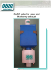
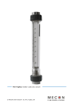
MANUAL
Anevac D
Before the system may be taken into use, this manual must be studied
carefully.
Edition 1:1999
Only, by MEDICVENT, authorized personnel are allowed to perform
adjustments or repairs on this equipment.
Only MEDICVENT original parts may be used in repairs.
MEDICVENT reservs the right to perform changes, regarding
construction and usage, without previous notice.
Table of contents
Chapter
System components
Installation
Page
3.
4-5.
Handling
6.
Technical Data
7.
Maintenance
8.
Safety
9.-
2
System components
Anevac D
9
13
12
ATT, see points 12, 13 below
10
2
1
8
3
6
4
11
5
7
1. The Double nose mask (3 sizes) consists of an
inner mask from Matrix (USA) and an outer
mask of Polysulfon specially adapted by Medicvent. The inner mask is softly concave to achieve
an optimal fit to the patients face.
The outer mask can be manufactured for other products as well as this one.
6.
7.
8.
9.
10.
11.
2. A coupling house specially designed to enable
connection of the evacuation hose to the nose
mask.
Accessories:
3. Evacuation hose from nose mask (Ø 19 mm)
4. Chin mask of transparent silicon. The mask is
kept in place by a strong plastic snap equipped
rubber strap, which can be used several times.
Distributor block
Flow meter with cutdown
Evacuation tube (Ø 40 mm)
Control box which remote controlles the fan unit
Auxiliary cable
Breathing circle from/to analgesia device.
12. Silencer
13. Regulating valve
ATT: Points 12 and 13 are used when there is a
central fan unit with sufficient capacity
even for Anevac D.
5. Evacuation hose from chin mask (Ø 19 mm)
3
Installation
Anevac D
Preparations
Anevac D is delivered hygienically packaged. The
parts included in the package should be cleaned
before usage. For instructions look up page 5 “Handling” and heading “Clean and disinfect”.
Connection
1. Mount the flow meter so that the indicator arrow
points upwards. Install the meter in a suitable
place so that all hoses come from the same
direction.
2. Connect the evacuation tube (Ø 40 mm) to the
flow meter.
If Medicvent ejector is used, connect it to the
left side of the flow meter with the bayonet
coupling downward. Then connect the evacuation
tube to the ejector.
Stationary fanunit:
3. Connect the other end of the evacuation tube
(Ø 40 mm) to the Anevac systems outlet
where this outlet is placed. (Normally, wall
outlet in carerooms wall panel)
4. Connect the control box to the stationary
mounted connection with the auxiliary cable.
N.B!
If central fan unit is used; connect the silencer and the regulating valve to the
evacuation outlet and then connect the
evacuation tube to the silencer (See component description previous page) The
regulating valve is used to obtain the
correct evacuation flow.
It is important to verify that the fan unit
used, has enough capacity to meet up with
Anevac D:s demands on evacuation flow,
before installation of this alternative.
Mobile fanunit:
3. Connect the other end of the evacuation tube
(Ø 40 mm) to the fan units inlet marked with
an arrow that points inwards.
WARNING!
Must be installed correctly! The left inner
connection, seen from behind. If not polluted air will be blown through the Anevac
system.
3a. Also connect another evacuation tube (Ø
40 mm) to the fan units outlet marked with
an arrow that points outwards. Connect
the other end of the tube to a suitable evacuation device.
3b. Connect the safety isolating transformers
connection device to the fanunit. This applies
especially to hospitals.
WARNING!
A system without a safety isolating
transformer does not comply with norm
IEC 601:1. Sensitive equipment might be
disturbed.
3c. Connect the Mains cable from the safety
isolating transformer to suitable power
supply.
4. Connect the control box to the fan unit with
the auxiliary cable.
5. Connect the distributor block to the flow meter.
6. Connect the evacuation hoses (Ø 19 mm) for
nose- and chin mask to the distributor block.
7. Connect the evacuation hoses other end to the
chin mask respectively coupling house.
The coupling house is 360o turnable so that the
hose can be placed in such a way that it doesn´t
interfere with the treatment.
4
Installation
Anevac D
8. Connect the nose mask to the coupling house.
9. Connect the breathing hoses from the analgesia
device to the nose mask. One hose on each side
of the mask.
10. If the analgesia device doesn´t have a nonreturn
valve, one can be attached to the breathing circle
in the form of an Anevac D/HB-set.
Flowmeter:
11. Test the analgesia system for leaks and function
together with the coupling house and the nose
mask.
12. Activate the fan with the control boxes on/offswitch.
13. In this Anevac system a flow meter with three
engraved marks is used. The marks corresponds
to different air flows:
Upper mark (high flow) = 35 m3/h (583 l/min)
Middle mark
= 27 m3/h (450 l/min)
Lower mark (low flow) = 17 m3/h (290 l/min)
On the control box there are two adjustment
screws for high- and low flow. High flow is normally adjusted to lie between 27–35 m3/h, i.e.
between the two upper marks, when chin masks
from two patients are hooked up to evacuate
expiration gases.
When only one chin mask is hooked up the fan
unit is run on low flow, which has been adjusted
to approx. 17 m3/h, i.e. the lower mark.
Controlbox:
high flow
adjustment
low flow
adjustment
low flow
high flow
5
Handling
Anevac D
Directions for use
Clean and disinfect
• Activate the fan with the control boxes on/offswitch.
All close to patient details, the double nose mask, the
chin mask, the coupling house, the rubber strap, the
distributor block, the evacuation hoses (Ø 19 mm),
and the regulating device can be autoclaved in 120° C
or washed in a decontaminator without any affects on
the materials. Flow meter and control box need only
be surface disinfected.
In reference to cleaning and disinfecting the
Anevac systems components can be divided into
three groups:
• Check the evacuation flow against the flow meter
(See Installation, previous page).
If indication by the flow meter is incorrect a
leakage in the system might be suspected. Then
check the hose connections or contact technical
support at your hospital.
• Important!
Use a hose holder when possible. This is to enable
positioning of the hoses so that as little effort as
possible is needed to hold the mask in place.
• The coupling house is 360° turnable so that the
hose can be placed in such a way that it doesn´t
interfere with the treatment.
• The mask is held against the patients face by the
analgesia hoses which are attached together with a
hose clip, behind the patients head.
• The mask can be removed from the patients face
and put aside, without the gas flow having to be
shut off or readjusted. There is no risk of gas
spreading out into the surrounding air since it is
evacuated with the air flowing in between the
outer- and the inner mask.
• Attach the chin mask to the patients face with the
enclosed rubber strap which should be placed around the patients head.
Local evacuation (point-evacuation)
Anevacs evacuation system can be used as local
evacuation.
Group 1
Decontaminator (80–85°C) or autoclave (120° C):
Double nose mask (all parts)
Chin mask (all parts)
Coupling house (all parts)
Hoses of hytrel
Distributor block
Regulating device
Anevac D/HB nonreturn-valve set
Group 2
Washing in mild detergent (60–70° C):
Evacuation tube Ø 40 mm
Soft muffs
Group 3
Wipe off with disinfectant:
Flow meter
Control box
Cables
Ejector
Silencer
Fan unit (if it is located in the same room as the
patient)
Safety isolating transformer (used in mobile
fan unit)
N.B!
Detergent with a high pH-value might cause discolouration of the aluminium
connections (flow meter). Some alcohol
dissolvents might cause damages to the flow
meter (acrylic plastic) and the control box.
6
Technical data
Anevac D
Component
Material
Cleaning grp.
Double nose mask, compl. outer mask Transparent polysulfon
inner mask Matrix (porter)
Group 1
Coupling house, complete
Transparent polysulfon
Group 1
Chin mask
Transparent silicon
Group 1
Strap with plastic snaps
EPDM rubber
Group 1
Analgesia hoses
Hytrel
Group 1
Anevac D/HB nonreturn valve set
Pom Acetal
Group 1
Evacuation hose (Ø 19 mm)
Hytrel
Group 1
Distributor block
Acetat
Group 1
Flow meter
Aluminium alloy, akryl
Group 3
Muff (Ø 40 mm)
PVC
Group 2
Evacuation tube (Ø 40 mm)
PVC
Group 2
Control box
PVC
Group 3
Auxiliary cable
PVC
Group 3
Silencer
Aluminium
Group 2
7
Maintenance
Anevac D
Flow meter
Annual cleaning, i.e. blow through the canals and
check calibration.
If the system works in accordance with this manual
and the flow meter at hand, there is no further need
for any service or maintanence.
Hytrelhoses
• Recommended time of use max 24 months or 200
washings.
• Store dark. Avoid sunlight during use.
• Always perform tightness test before use.
• Spare hoses must always be at hand.
• Hose that has turned yellowish must be replaced.
8
Safety
Anevac D
WARNING!
Constitutes a risk for injuries on
patient and user.
N.B!
Constitutes a risk for damages to
equipment. Only use components
that MEDICVENT has delivered
and/or approved.
ATT:
Attention, reference.
Safety Anevac D
• Only by MEDICVENT authorized personnel are
allowed to perform adjustments or repairs on this
equipment.
• Only MEDICVENT original parts may be used in
repairs.
WARNING! When using a mobile fan unit the
evacuation tube from the flow meter
must be attached correctly. It must
be attached to the fan units inlet
marked with an inward pointing
arrow. Otherwise polluted air will be
blown through the patient system.
WARNING! A system without a safety isolating
transformer does not comply with
norm IEC 601:1. Sensitive equipment might be disturbed.
N.B!
If central fan unit is used; connect the
silencer and the regulating valve to the
evacuation outlet and then connect the
evacuation tube to the silencer (See
page Systemcomponents). The
regulating valve is used to obtain the
correct evacuation flow.
It is important to verify that the fan
unit used, has enough capacity to meet
up with Anevac D:s demands on
evacuation flow, before installation of
this alternative.
N.B!
Detergent with a high pH-value might
cause discolouration of the aluminium
connections (flow meter). Some
alcohol dissolvents might cause
damages to the flow meter (acrylic
plastic) and the control box.
9