1
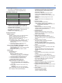
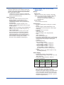
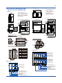
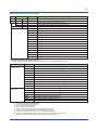
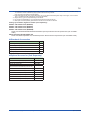
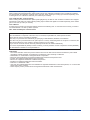
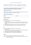
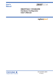
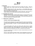
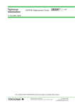
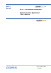
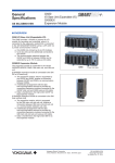
General Specifications GX10/GX20 Paperless Recorder (Panel mount type) GS 04L51B01-01EN OVERVIEW The GX10/GX20 are paperless recorders that display real-time measured data on a touch screen and save data on an external storage medium (SD card). For the input/output module specification, please see GX90XA/GX90XD/GX90YD/GX90WD Input/Output Module General Specification (GS 04L53B01-01EN.) ● The number of analog input is a maximum of 100 channels in GX10 with expandable I/O, and a maximum of 450 channels in GX20 with expandable I/O. * Max. number of input/output channels is 500 channels. ● The GX10/GX20 have the large internal memory (GX10/GX20 standard type: 500MB, GX20 large memory type: 1.2 GB), and prolonged record and preservation are possible. ● As the input signal, a DC voltage, thermocouple, resistance temperature detector, DI (DCV input (TTL), contact signal), or mA (DC current) can be set to each channel. ● Input and output have module structure and it can extend them easily. (GX10: max. 3*, GX20: max. 10*) * In case of using expandable I/O, GX10 can extend two units, GX20 can extend 9 units. ● A module type is four types, an analog input, a digital input, a digital output, and a digital input/ output. ● A maximum of six units of expandable I/O can be connected to GX10/GX20. Each expandable I/O can incorporate a maximum of six modules. With expandable I/O connected, the large memory type GX10 and GX20 can use multiple channels. Furthermore, the I/O ports can be installed in separate locations from where GX10/GX20 is located, helping you reduce wiring requirements and build a decentralized configuration. ● The intuitive operation by flick, pinch in, pinch out, and swipe are possible. ● The past trend under recording can be seamlessly displayed on a trend screen. ● Moreover, the measurement data of the time specified on the calendar screen can be searched and displayed. ● Various functions, such as a freehand message, a PDF/Excel output of a report file, a direct output to a network printer, a scale movement of a trend display, and a buzzer sound, are equipped. ● It can be hooked up to network via Ethernet, which enables to inform by Email and to monitor on Web site as well as to transfer files by using FTP. Also, it can communicate with Modbus/RTU or Modbus/ TCP. ● A setup of GX can be performed on-line from the web browser on PC. A setup by off-line is also possible. ● Universal Viewer software allows a PC to display waveforms on its screen and to print out waveforms. GX10 GX20 ● The measuring accuracies noted in the general specifications have a margin of error that takes into account the product's components and the equipment used for adjustment and testing. However, the actual values calculated from the accuracy testing data upon shipment of the instrument from the factory are as follows. Input type Measuring accuracy*1 (typical value*2) DCV 20 mV ± (0.01% of reading + 5 μV) 6V (1-5V) ± (0.01% of reading + 2 mV) Pt100 ± (0.02% of reading + 0.2 °C ) Pt100 (high resolution) ± (0.02% of reading + 0.16 °C) RTD *1 General operating conditions: 23±2 ºC, 55±10% RH, supply voltage 90–132, 180–250 VAC, supply frequency within 50/60 Hz ±1%, warmup of 30 minutes or more, no vibrations or other hindrances to performance. *2 For the measuring accuracy (guaranteed), see the module's general specifications (GS04L53B01-01EN). MAIN UNIT SPECIFICATIONS ■ FUNCTIONAL SPECIFICATION Input Specifications Please see GX90XA/GX90XD/GX90YD/GX90WD I/O Module General Specifications. Model Name GX90XA Analog input module General Specification No. GS 04L53B01-01EN GX90DX Digital input module GX90YD Digital output module GX90WD Digital input/output module Yokogawa Electric Corporation 2-9-32, Nakacho, Musashino-shi, Tokyo, 180-8750 Japan GS 04L51B01-01EN ©Copyright November 2012 8th Edition April. 7, 2014 2 Measuring Functions • The number of installable modules and I/O channels (total for GX and expandable I/O) GX10/GX20 standard type Item GX10/GX20 standard type Number of module Max. 10 Number of input/output module Max. 100 GX20 large memory type Item GX20 large memory type Number of module Max. 45 Number of input/output module Max. 500 (or max. 450 for AI only) Restrictions of module connection: • A maximum of 10 modules can be installed, as a total for GX90YD digital output modules and GX90WD digital I/O modules. • A maximum of one GX90WD digital I/O module can be installed in GX and in each expandable I/O. • Expandable I/O connection Number of connectable units: Max. 6 Display Functions Display groups: Number of groups; GX10: 30, GX20 standard type: 50, GX20 large memory type: 60 Number of channels that can be assigned to each group; GX10: 10, GX20: 20 Scan interval: 100*1*2, 200*1*2, 500 ms*1, 1, 2, 5 s *1 Cannot be specified if an electromagnetic relay scanner type (Type Suffix Code: -T1) analog input module is in use. *2 Cannot be specified for L-model DCV/TC/DI, scanner type (Type Suffix Code: -L1). Display color (Trend/Bar graph/Digital display): Channel: Select from 24 colors A desired display color can be selected freely using its RGB value. Background: Select from white or black Display type: ● Trend display (T-Y) Display method: Direction: Horizontal, vertical Trend interval: 5*1*2, 10*1*2, 15*1, 30 s/div, 1, 2, 5, 10, 15, 20, 30 min/div, 1, 2, 4, 10 h/div *1 Cannot be specified if an electromagnetic relay scanner type analog input module is in use. *2 Cannot be specified for L-model DCV/TC/DI, scanner type (Type Suffix Code: -L1). Trend line width: Thick, normal, thin Scale; GX10: Max. 6, GX20: Max. 10 Current value bar graph, color scale band, and alarm point marks can be displayed on the scale. Moving scale; Scale can be moved on any waveform. A bitmap image scale can be attached. Others; Grid (Auto, 4 to 12), Trip line, Message, Zone display, Partial expanded display All Rights Reserved. Copyright © 2012-2014, Yokogawa Electric Corporation ● Historical trend display (T-Y display) Redisplays the display data or event data in the internal memory or external storage medium Time axis operation: The time axis can be reduced or expanded. Data search: Waveforms from the internal memory can be displayed through the specification of a date and time, calendar, each summary Moving scale; A bitmap image scale can be attached. All historical trends can be displayed in one screen. ● Bar graph display Direction: Vertical or horizontal Scale: Display a scale for each channel Color scale band, and alarm point marks can be displayed on the scale. ● Digital display Displays measured values numerically A DI input state can be displayed as an arbitrary character string (0=Off/1=On, etc.) Update rate: 0.5 s ● Overview display Display format: All channels, each groups Displays the measured values of all channels and the alarm statuses ● Alarm summary display Displays a log of up to 1000 alarms Specify an alarm with the cursor and jump to the corresponding section on the historical trend display. ● Message summary display Time and content of up to 500 messages (including 50 add messages) Specify a message with the cursor and jump to the corresponding section on the historical trend display. ● Memory summary display Displays the information (up to 500) of the data in the memory Specify a file with the cursor and jump to the corresponding section on the historical trend display. ● Report display Displays the report data residing in the internal memory For more details, see "MATHEMATICAL FUNCTIONS WITH REPORT FUNCTION (/MT)." ● Log display Displays the event log, error log, communication log, FTP log, Web log, e-mail log, SNTP log, DHCP log, and Modbus log. ● Multi-panel display Divides the screen into two to six sections and displays some different display formats. ● Internal switch/relay state display Displays the internal switch and ON/OFF state of DO Operates the internal switch and ON/OFF state ● Other displays Network information display System information display System configuration display GS 04L51B01-01EN Apr. 7, 2014-00 3 Auto scroll ON/OFF: The displayed groups can be automatically switched at a specified interval. The display switches in ascending group order. Names of channels: X X X X Channel number; Analog input: 01 to 10 Digital input: 01 to 16 Digital output: 01 to 06 Digital input/output; DI: 01 to 08, DO: 09 to 14 Slot number; GX10: 0 to 2, GX20: 0 to 9 Expandable I/O: 0 to 5 Unit number; Main unit: 0, Expandable I/O: 1 to 6 Tags: • Tag and Tag numbers can be displayed. • Tag number; Number of characters: Up to 16 Displayable characters: Alphanumeric characters Tag numbers can be enabled or disabled. • Tag; Number of characters: Up to 32 Displayable characters: Alphanumeric characters Message: • Write messages to the trend display. • Number of messages: 100 • Number of characters: Up to 32 • Write method: Write a preset message or write an arbitrary message on the spot. • Write destination: Select only the displayed group or all groups. • Auto message: Write a message when the GX recovers from a power failure while memory sampling is in progress. Write a message when the trend interval is switched during memory sampling. Add message: • Write messages to the past data positions. • Message: The same as the “Message” item above Number of writable messages per file: 50 messages (including 10 freehand messages) Freehand message: • Can be written by dedicated pen. Number of writable messages per file: 50 messages (including 10 Add messages) Data Saving Functions Internal memory: • Temporarily saves various types of data. • Medium: Flash memory • File storage capacity; GX10, GX20 standard type: 500 MB GX20 large memory type: 1.2 GB External storage medium: • Medium SD card (SD/SDHC) (up to 32 GB) • Format: FAT32 or FAT16 Data type: • Display data, Event data, Alarm summary data, Manual sampled data, Screen image data, Setup data, and Report data All Rights Reserved. Copyright © 2012-2014, Yokogawa Electric Corporation Display data: • Target: Measurement (input/output module)/ math/communication channels, alarm summary, message summary Description: Maximum or minimum value per recording interval • Recording intervals: Determined by the trend interval, recording data type (display data/display data + event data, GX20 large memory type) For GX20 standard type Trend interval (div) Number of channels 5s 100 10 s 200 15 s or longer 500 For GX20 large memory type Trend interval (div) Number of channels Display data Display data + Event data 5s 200 100 10 s 500 200 15 s 1000 500 30 s or longer 1000 1000 Note that the maximum number of channels is fixed at 100 in the GX10. • Data size; Analog input data: 12 bytes/ch. Digital I/O data: 4 bytes/ch. Math channel data: 12 bytes/ch. Communication channel data: 12 bytes/ch. • File size: Up to 18 MB • Number of files for GX10, GX20 standard type: Up to 500 (including event data), for GX20 large memory type; Up to 1000 (including event data) Operation in the internal memory: FIFO (First In First Out) • Data format: Binary or text • Recording: Records data at all times. • Display data file sample time Measurement channel = 30. Math Channel = 0 Internal Memory 500 MB Trend interval (minute/div) 30 minutes Recording interval (s) 60 s Total sample time Approx. 2.5 years Event data: • Target: Measurement (input/output module)/ math/communication channels, alarm summary, message summary, operation log Description: Instantaneous value per recording interval • Recording intervals: Determined by the sample rate, recording data type (display data/display data + event data, GX20 large memory type) For GX20 standard type Sampling rate Number of channels 100 ms 100 200 ms 200 500 ms or longer 500 GS 04L51B01-01EN Apr. 7, 2014-00 4 For GX20 large memory type Trend interval (div) Number of channels Display data Display data + Event data 100 ms 500 100 200 ms 500 200 500 ms 1000 500 1 s or longer 1000 1000 Note that the maximum number of channels is fixed at 100 in the GX10. • Data size; Analog input data: 6 bytes/ch. Digital I/O data: 2 bytes/ch. Math channel data: 6 bytes/ch. Communication channel data: 6 bytes/ch. • File size: Up to 18 MB • Number of files for GX10, GX20 standard type: Up to 500 (including display data), for GX20 large memory type; Up to 1000 (including display data) • Operation in the internal memory: FIFO (First In First Out) • Data format: Binary or text • Mode; Free: Records data at all times. Trigger: Starts recording data when a certain event occurs and records for the specified interval. Repetition trigger: Repeat Trigger mode • Event data file sample time Measurement channel = 30. Math Channel = 0 Internal Memory 500 MB Recording interval (s) 1s Total sample time Approx. 1 month Alarm Functions • Number of alarms: Up to four alarms (level) for each measurement channels • Alarm type: High limit, low limit, difference high limit, difference low limit, high limit on rate-ofchange alarm, low limit on rate-of-change alarm, delay high limit, and delay low limit • Alarm delay time: 1 s to 24 hours (for each channel) • Rate-of-change calculation interval of rate-ofchange alarms: 1 to 32 times the scan interval (common to all channels) • Hysteresis: 0.0 to 5.0% of the span (for each alarm (level)) • Alarm output: Output to the internal switch Internal switch operation: AND/OR operation selectable • Display: Displays the status on the respective operation screen and an alarm icon on the status display section when an alarm occurs. Display operation: Hold or not hold the display until the alarm acknowledge operation • Alarm hide function (alarm no logging function) Not display alarms nor record to the alarm summary (for each channel) • Alarm information: Displays a log of alarm occurrences on the alarm summary All Rights Reserved. Copyright © 2012-2014, Yokogawa Electric Corporation • Reflash: The duration for which the reflash relays are deactivated can be set to 500 ms, 1 s, or 2 s. • Individual alarm ACK function: Alarm display and relay output can be cancelled on individual alarms Event Action Functions • Event action: Execute a specified operation when a given event occurs. • Number of settings: 50 Events: Remote control input, etc. Timer; Number of timers: 4 Match time timer; Number of timers: 4 Action: Specify memory start/stop, alarm ACK, etc. Security Functions • Operation lock function: Limitations to touch operation, access to the external storage medium, and various operations • Login function: Only registered users can operate the GX. It can be set to each of touch operation and communication access. System administrators and Users: 50 (totally) Number of Authority of user: 10 level Manual Sampled Data • Item: Instantaneous value at an arbitrary time • Target: Measurement (input/output module)/ math/communication channels • Number of recording channels; GX10, GX20 standard tyep: Max. 50 GX20 large memory type: Max. 100 • Maximum number of data values that the internal memory can store: 400 • Data format: Text Report Data • Item: Report at each scheduled time of report • Target: Measurement (input/output module)/ math/communication channels • Maximum number of reports that the internal memory can store: 800 • Data format: Text Snapshot Data • Item: Displayed screen image data • Data format: PNG • Output destination: External medium or communication output Setup Data • Item: GX setup data • Data format: Text • Output/read destination (for saving/loading): External medium Clock Functions • Clock: With a calendar function • Accuracy: ± 5 ppm (0 to 50°C), excluding a delay (of 1 second, maximum) caused each time the power is turned on. • Time setting: Using touch operation, communication command, event action function, or SNTP client function GS 04L51B01-01EN Apr. 7, 2014-00 5 • Modbus server: Loads measurement and math channel data Loads and writes communication channel data Some control commands such as memory start Modbus client* register access limitations *: Required /MC option Number of the simultaneous connection: Max. 4 • Setting/Measurement server: Operate, set, and output data of the GX using a dedicated protocol. • DARWIN compatible communication server: Supports some DARWIN commands Communication with GX is possible using DARWIN communication commands. • Output-related commands: Output measurement (IO) channel data, Output calculation channel data, Output relay status, Output the position of the decimal point for the measurement (IO) channel, Output the position of the decimal point for the calculation channel, Output the information on system configuration • Setup-related commands: Range, Scale unit, Alarm, Time, Moving average • Operation-related commands: Reset alarm, Reset timer, Start MATH calculation, Rebuild system, Initialize, Input communication, Output communication DO, Write message • Time adjustment method: Limit in which the time is gradually adjusted: Select from the available settings between 5 s and 15 s. Whether to change an out-of-limit operation immediately or report it as an error can be selected. While memory sampling: Corrects the time by 1 ms for each second. While memory is stopped: Immediately change the time. • DST: The date/time for switching between standard time and DST can be specified. • Time zone: Sets the time difference from GMT. • Date format: Select "YYYY/MM/DD", "MM/DD/ YYYY", "DD/MM/YYYY" or "DD.MM.YYYY". MM expression can be selected from the numeric character or ellipsis. Ex. January: 01 or Jan The delimiter can be selected from "/", ".", "-". Ethernet Communication Functions • • • • • • • • • • • • • • Electrical specifications: Conforms to IEEE 802.3 Connection: Ethernet (10BASE-T/100BASE-TX) Max. segment length: 100 m Max. connecting configuration: Cascade Max. 4 level (10BASE-T), Max. 2 level (100BASE-TX) Connector: RJ-45 Protocols: TCP, UDP, IP, ICMP, ARP, DHCP, HTTP, FTP, SMTP, SNTP, Modbus, and dedicated protocols E-mail client: Automatically send e-mail at specified times. E-mail is sent by events as below. - Alarm occurring/alarm canceling - Recover from power failure - Report data generating - Storage medium error, FTP client function error - Specified time period POP before SMTP and SMTP authentication (PLAIN and CRAM-MD5) is available. FTP client: Automatically transfer data files to the FTP server. Applicable files: Display data, event data, screen image data, report data, etc. FTP Server: Transfer files, delete files, manipulate directories, and output file lists of the GX. Number of the simultaneous connection: Max. 4 Web server: GX real-time monitoring and setting changes/operations can be performed with the Web browser. The screen layout can be determined independently of the screen of the GX main unit. Number of the simultaneous connection: Max. 4 SNTP client: Inquires the time to the SNTP server and sets the GX. SNTP server: Outputs the GX time. Time resolution: 5 ms DHCP client: Automatically obtain the network address settings from the DHCP server. Modbus client: Reads data from another device and writes to the registers. Number of connectable sever; GX10, GX20 standard type: Max. 16 GX20 large memory type: Max. 32 All Rights Reserved. Copyright © 2012-2014, Yokogawa Electric Corporation Batch Function • Function: Data management using batch names. Enter text fields and batch comments in the data file. • Batch name: Added to the file name of the display data and event data. Structure: Batch number (up to 32 characters) + lot number (up to 8 digits) Use/not use selectable for lot number, on/off selectable for auto increment function. • Text field: Adds text to the display data and event data. There are 24 available text fields. Up to 20 title characters and 30 other characters can be entered per field. • Batch comment: Adds text to the display data and event data. 3 comments (max. 50 characters) are available. Printer Output Function • Snapshot Data can be printed out with any LAN-connected printer supporting the HP-PCL5c language. SSL Communication Functions Communication that sends and receives information encrypted by the SSL (Secure Socket Layer) protocol is possible. • Server function: Supported servers: HTTP server and FTP server (Port number: 443 when encryption is used) Private key: Created in GX and saved in the internal memory Server certificate: Server certificates created by users can be saved in the internal memory. Self-signed certificates can be created in GX. Client function: Supported clients: FTP client and SMTP client (Port number: 443 when encryption is used) Trusted certificate: Trusted certificates (a total of up to 100 KB) can be saved in the internal memory. GS 04L51B01-01EN Apr. 7, 2014-00 6 Electronic Signature Function Electronic signatures can be added to report files created in PDF format using the PDF form creation function. An electronic signature is provided each time a report file is created. • Certificate for electronic signature: Certificates for electronic signatures created by users can be saved in the internal memory. Other Functions • Buzzer: GX makes a buzzer sound at touch screen operation, or when alarm occurs. • Backlight saver function: Dim or turn off the LCD backlight if there is no key operation for a specified time. • Favorite display: Register frequently used displays to the Favorite and show them through simple operation. • The main alarm is indicated using the MENU key LED. No alarm: Blue (same condition as power-on) Alarm condition: Red. • User function feature: A button (user function key) to which the user can assign a desired function is provided. It can be assigned to an event triggered by the event action function. • Firmware update function: The Web application, the IO module, or the expansion module firmware can be updated by operating GX. HARDWARE SPECIFICATIONS (MAIN UNIT) Display Display unit*: GX10: 5.7-inch TFT color LCD (640 × 480 dots) GX20: 12.1-inch TFT color LCD (800 × 600 dots) * A small number of missing or steady-on LCD pixels and minor variations in brightness uniformity is a normal display characteristic and not a malfunction. Touch screen: 4 wire resistive touch screen Construction • Mounting: Flush panel mounting (on a vertical plane) • Mounting angle: Inclined backward up to 30 degrees from a horizontal plane. Left and right horizontal • Panel thickness: 2 to 26 mm • Material; Case: Metal plate Bezel and display cover: Polycarbonate • Color; Case: Smoke blue Bezel: Charcoal grey light • Front panel: Water and dust proof: Complies with IEC529-IP65 and NEMA No.250 TYPE 4 (except External Icing Test), except for side-by-side mounting • External dimensions: When installing modules GX10: 144(W) × 144(H) × 255(D) mm GX20: 288(W) × 288(H) × 220(D) mm When uninstalling modules GX10: 144(W) × 144(H) × 174(D) mm GX20: 288(W) × 288(H) × 169(D) mm (D: depth from the panel mounting plane) • Weight: GX10: Approx. 2.1 kg, GX20: Approx. 6.0 kg (excluding modules) Power Supply • Rated supply voltage: 100 to 240 VAC • Allowable power supply voltage range: 90 to 132, 180 to 264 VAC • Rated power supply frequency: 50/60 Hz • Power consumption: Supply voltage LCD backlight off Normal operation Maximum 100 V AC GX10: 16 VA GX20: 28 VA GX10: 20 VA GX20: 34 VA GX10: 48 VA GX20: 90 VA 240 V AC GX10: 24 VA GX20: 38 VA GX10: 30 VA GX20: 45 VA GX10: 60 VA GX20: 110 VA * The following combinations are assumed for LCD backlight off and normal operation. GX10: 1 AI module, 1 DO module, 1 DI module GX20: 5 AI modules, 4 DO modules, 1 DI module • Module power supply voltage: The total allowable power consumption of respective modules is up to 6 W in the GX10 and up to 20 W in the GX20. • Allowable interruption time: Less than 1 cycle of the power supply frequency All Rights Reserved. Copyright © 2012-2014, Yokogawa Electric Corporation GS 04L51B01-01EN Apr. 7, 2014-00 7 Isolation • Insulation resistance: Between the Ethernet, RS-422/485, and each insulation terminals and earth: 20 MΩ or greater at 500 VDC • Withstand voltage: Between the power terminal and earth: 3000 V AC at 50/60 Hz for one minute Between the contact output terminal and earth: 3000 V AC at 50/60 Hz for one minute Between the input/output modules and earth: Depends on the specification of I/O module. • Grounding: Be sure to set a low grounding resistance. • Isolation: FAIL output terminal Ethernet port RS-422/485 terminal Input and output module terminal Power terminal Input and output module internal circuit Earth (PE) terminal RS-232 terminal Internal circuit SD card slot USB port The circuits divided by lines are insulated mutually. Safety and EMC Standards • CSA: CSA22.2 No.61010-1, installation category II *1, pollution degree 2 *2, and CSA-C22.2 NO. 61010-2-030-12 • UL: UL61010-1, UL 61010-2-030 (CSA NRTL/C) • CE: EMC directive EN61326-1 compliance, Class A Table 2 EN61000-3-2 compliance EN61000-3-3 compliance EN55011 Class A Group 1 Low voltage directive EN61010-1, EN 61010-2-030 Installation category II *1 Pollution degree 2 *2 Measurement category *3 • EMC Regulatory Arrangement in Australia and New Zealand (RCM): EN55011 compliance, Class A Group 1 • KC marking: Electromagnetic wave interference prevention standard, electromagnetic wave protection standard compliance *1 Installation category (overvoltage category) II: Describes a number which defines a transient overvoltage condition. Implies the regulation for impulse withstand voltage. “II” applies to electrical equipment which is supplied from the fixed installation like a distribution board. *2 Pollution degree 2: Describes the degree to which a solid, liquid, or gas which deteriorates dielectric strength or surface resistivity is adhering. “2” applies to normal indoor atmosphere. Normally, only non-conductive pollution occurs. *3 Measurement category: Depends on the specification of each modules All Rights Reserved. Copyright © 2012-2014, Yokogawa Electric Corporation Category Measurement category II CAT II Available in the testing and measuring circuits directly connected to a usage location (receptacle or the like) of a low-voltage main power supply facility. Appliances, portable equipment, etc. III CAT III Available in the testing and measuring circuits connected to a power distribution portion of a low-voltage main power supply facility. Distribution board, circuit breaker, etc. IV CAT IV Available in the testing and measuring circuits connected to a power source of a lowvoltage main power supply facility. verhead wire, cable systems, etc. Description Remarks • WEEE Directive: Compliant Normal Operating Conditions • • • • • • • • • • • Power supply voltage: 100 to 240 V AC ±10 % Power supply frequency: 50/60 Hz ±2 % Ambient temperature: 0 to 50 °C Ambient humidity: 20 to 80 %RH (at 5 to 40°C) (no condensation) Magnetic field: 400 A/m or less (DC and 50/60 Hz) Vibration: 5 ≤ f < 8.4 Hz amplitude 3.5 mm (peak) 8.4 ≤ f ≤ 160 Hz acceleration 9.8 m/s2 Shock (IEC-60068-2-27): Non-energization, 500 m/s2 or less, approximate 10 ms, 6 directions (±X, ±Y, ±Z), 3 times in each direction Mounting position: Can be inclined up to 30 degrees backward. Left and right horizontal when installing the panel mount and wall mount. Altitude: 2000 m or less Installation location: Indoors Warm-up time: At least 30 minutes after power on Other Specifications • Memory backup: A built-in lithium battery backs up the settings and runs the clock • Recommended replacement periods of Battery: Approximately 10 years (at room temperature) Transport and Storage Conditions • Ambient temperature: –25 to 60°C • Ambient humidity: 5 to 95 %RH (no condensation) • Vibration: 10 to 60 Hz, 4.9 m/s2 maximum • Shock: 392 m/s2 maximum (in packaged condition) GS 04L51B01-01EN Apr. 7, 2014-00 8 EXTERNAL DIMENSIONS AND PANEL CUTOUT DIMENSIONS GX20: 280.2(11.03) Unit: mm (approx. inch) Unless otherwise specified, tolerance is ±3% (however, tolerance is ±0.3 mm when below 10 mm). GX10: 136.5 (5.37) Unit: mm (approx. inch) Unless otherwise specified, tolerance is ±3% (however, tolerance is ±0.3 mm when below 10 mm). (Dimension before fitting attachment) 288(11.34) 144(5.67) 173.1(6.81) (*2) 9.4(0.37) 22.8 (0.90) 157.7(6.21) 2(0.08) to 26(1.02) Panel cut dimensions Single-Unit Mounting 148(5.67) 7.5 136.5 (0.30) (5.37) 103.3(4.07) 144(5.67) 151.5(5.96) 40.9(1.61) 26.6(1.05) 32.3(1.27) 247.4(9.74) (Dimension after fitting attachment) *1: with modules *2: without moduels (Dimension after fitting attachment) Side-by-Side Mounting (horizontally) 137 +20 (5.39) *1: with modules *2: without moduels Panel cut dimensions +2 L+20 L+20 361 min. (14.21) 281 0 (11.06) 137 (5.39) 137+20 (5.39) 175 MIN (6.89) 360 min. (14.17) 175 MIN (6.89) +2 0 Side-by-Side Mounting (vertically, max. 3 units) 137+20 (5.39) 280.2(11.03) Thickness of attachment panel Thickness of attachment panel 103.3(4.07) MAX 219.2(8.63) (*1) 168.8(6.65) (*2) 152.6(6.01) 2(0.08) to 26(1.02) 288(11.34) 295.2(11.62) 151.5(5.96) 144(5.67) 40.9(1.61) 28.2 (1.11) 9.4(0.37) 295.2(11.62) MAX 224.4(8.83) (*1) 7.5(0.30) (Dimension before fitting attachment) +2 Units 2 3 4 5 6 7 8 9 10 n +2 L0 282 (11.10) 426 (16.77) 570 (22.44) 714 (28.11) 858 (33.78) 1002 (39.45) 1146 (45.12) 1290 (50.79) 1434 (56.46) (144×n)-6 281 0 (11.06) Rear view I/O module (slot 9) I/O module (slot 8) I/O module (slot 7) I/O module (slot 6) I/O module (slot 5) I/O module (slot 4) I/O module (slot 3) I/O module (slot 2) I/O module (slot 1) I/O module (slot 0) Rear view I/O module (slot 2) I/O module (slot 1) I/O module (slot 0) Power supply terminal RS-422A/485 terminal (/C3) or RS232 terminal (/C2) USB port (/UH) Ethernet port FAIL/STATUS terminal (/FL) VGA output terminal (/D5) Power supply terminal RS-422A/485 terminal (/C3) or RS232 terminal (/C2) USB port (/UH) Ethernet port FAIL/STATUS terminal (/FL) All Rights Reserved. Copyright © 2012-2014, Yokogawa Electric Corporation GS 04L51B01-01EN Apr. 7, 2014-00 9 SPECIFICATIONS OF OPTIONAL FUNCTIONS • ADVANCED SECURITY FUNCTION (/AS) Security and electronic record/signature functions have been added that are compliant with the USA’s FDA title 21 CFR Part 11. • Enabling/disabling the advanced security function: You can enable or disable the advanced security function. * • • • • • • The set values and data stored in the internal memory are initialized each time the function is enabled or disabled. • Data anti-tamper function: Settings and measured data are saved as encrypted binary files. • Data type: Only for display or event Trigger mode is not possible with event data. • Login function: Using the login function described below, you can enter security settings on the instrument • User name • Password • User ID (depend on setting) • User level and number of users: System administrator (all can be operated), General user (With user restrictions, you can set restrictions on performing operations and sign authority.), Monitor user (monitoring only), totally 100 users • User restrictions setting: 10 kinds (for general users) • Password expiration time: select form Off, 1month, 3 month, 6month • Password control function: Logins are verified by a Kerberos v5 authentication server* (only user name and password) Encryption method: AES128-CTS-HMAC-SHA1-96 AES256-CTS-HMAC-SHA1-96 ARCFOUR-HMAC-MD5 Pre-Auth function: use * The function has confirmed compatibility with Windows Server2003 SP2/Windows Server2008 SP2/Windows Server2012 ActiveDirectory • Signature function: After checking data that has finished being recorded, you can add three levels of electronic signature, select a pass/fail, and enter comments (50 characters maximum) • Audit trail function: The operation log, the settings change log and the settings file when the change was made are saved. SERIAL COMMUNICATION INTERFACE (/C2, /C3) • Connection: EIA RS-232(/C2) or EIA RS422/485(/C3) • Protocol: Dedicated protocol or Modbus protocol • Setting/measurement server function: Operation, setting or output of measurement data are available by dedicated protocol. • Synchronization: Start-stop synchronization • Transmission mode (RS-422/485): RS-422: Four-wire half-duplex multi-drop All Rights Reserved. Copyright © 2012-2014, Yokogawa Electric Corporation • • • connection (1:n (n = 1 to 31)) RS485: Two-wire half-duplex multi-drop connection (1:n (n = 1 to 31)) Baud rate: 1200, 2400, 4800, 9600, 19200, 38400, 57600, or 115200 bps Data length 7 or 8 bits Start bit: 1 bit Stop bit: 1 bit or 2 bit Parity: ODD, EVEN, or NONE Handshaking Off: Off, XON: XON, XON: RS, and CS: RS Communication distance; RS-422/485: 1200 m, RS-232: 15 m Modbus/RTU communication: Reading or writing of measurement data on other instruments is available by Modbus protocol. Communication channel function option (/MC) is needed to read measurement data from other instruments. Operation modes: Master or slave Execution of a communication command using a bar code: The entered text can be executed as a communication command. CUSTOM DISPLAY (/CG) Using DXA170 DAQStudio, screen creation software, a custom screen can be constructed and displayed in which display components (such as trend, digital, and bar graphs) are freely placed. The screen data is transferred from DAQStudio to the internal memory via communication, or loaded from an external medium to the internal memory and displayed. • Number of screens: 30 (internal memory) • Display components: • Normal components (digital value, bar graph, tag No., tag comment, simple digital value, simple bar graph, alarm mark, unit, alarm indicator, lower-limit span value, upper-limit span value, group name, system icon, memory sample bar, date/time view, batch name, and user name) • Trend components (trend group display (with scale board)) • List components (alarm list view and message list view) • Operation components (DO (DO operable), internal switch (internal switch operable), numeric value operations (viewing data of and writing data to communication channels), and button operations (writing numeric values, operating bits, switching screens, and executing communication commands) • Text components (labels) • Figure components (line view, rectangle view, and circle view) • Figure components (line view, rectangle view, and circle view) • Configuring screens: Screen creation software Creation using DXA170 DAQStudio (GX does not have a creation function) • Saving/loading screen data: A specified screen or all the screens is/are loaded from an external storage medium to the internal memory, or a specified screen or all the screens in the internal memory is/are saved on an external storage medium. GS 04L51B01-01EN Apr. 7, 2014-00 10 VGA VIDEO OUTPUT (/D5) (Only for GX20) • External display: Resolution: 800 × 600 dots (VGA) Connector: 15-pin D-Sub EtheNet/IP COMMUNICATION (/E1) Can be joined to an Ethernet/IP network as an adapter (or a server). • Loading data from the I/O channel or calculation channel • Loading and writing data from/to the communication input channel WT COMMUNICATION (/E2) Collects data by connecting to WT equipment manufactured by Yokogawa Meters & Instruments Corp. via Ethernet communication. • Supported models: WT1800, WT500, and WT300 • Number of connectable units: GX10: 8 GX20: 16 • Communication cycle: 500 ms/1 s/2 s/5 s/10 s/15 s/20 s/30 s • Types of data that can be obtained: Voltage, current, power, power factor, phase, electrical energy, high-frequency wave, etc. FAIL OUTPUT (/FL) • Contact: C contact, 1 point • FAIL output: The relay contact output on the rear panel indicates the occurrence of CPU failure. Relay operation: Energized during normal operation and de-energized on CPU failure. • Status output: The relay contact, which is deenergized in normal output state, is energized upon the occurrence of a memory/media error, measurement error, communication error, recording stop, or alarm. • Rated power supply voltage: 24 V DC or 250 V AC or less • Rated load current: 3A (DC)/3A (AC), resistance load • Min. load current: 100 mA • Recommended replacement periods of contact: Electrical: 30,000 more ON-OFF operations, Mechanical: 5,000,000 more ON-OFF operations Log SCALE (/LG) A logarithmic voltage that has been converted from a physical value is applied to the GX, and then the GX’s Log scale (logarithmic scale) is used to display and record the physical value. • Input type: Log input (logarithmic input), Pseudo log input: An input that supports pseudo logs, Log linear input: Input that is linear on a logarithmic scale. • Range: 20mV/60mV/200mV/1V/2V/6V/20V/50V All Rights Reserved. Copyright © 2012-2014, Yokogawa Electric Corporation • Scalable range: • Log input: 1.00E-15 to 9.99E+15 (15decade maximum) Scale_L < Scale_U If the lower limit mantissa is 1.00, the difference between the exponents must be 1 or more. If the lower limit mantissa is a value other than 1.00, the difference between the exponents must be 2 or more. • Pseudo Log Input/Log linear input 1.00E-15 to 9.99E+15 (15decade maximum) The higher limit mantissa is the same as the lower limit mantissa). If the lower limit mantissa is 1.00, the value must be between 1.00E–15 and 1.00E+15, the difference between the exponents must be 1 or more, and the maximum decades is 15. If the lower limit mantissa is a value other than 1.00, the value must be between 1.01E–15 and 9.99E+15, the difference between the exponents must be 1 or more and the maximum decades is 15. • Alarm type: High limit, low limit, delay high limit, and delay low limit • Alarm setting range: The range converted into the LOG scale corresponding to -5% to 105% of the span width. • Alarm hysteresis: Fixed to 0 • Green band setting range: The lower limit to the upper limit of the scale. However, the lower limit of the display position must be smaller than the upper limit. • Position of the decimal point: 1 to 2 • Misc: Nonlinear input is possible by correcting the input value MATHEMATICAL FUNCTIONS WITH REPORT FUNCTION (/MT) Mathematical Function: • Number of math channels; GX10: 50, GX20: 100 • Operation: General arithmetic operations: Four arithmetic operations (+, -, *, /), square root, absolute, common logarithm, natural logarithm, exponential, and power Relational operations: <, ≤, >, ≥, =, and ≠ Logic operations: AND, OR, NOT, and XOR Statistical operations: TLOG or CLOG Special operations: PRE, HOLD, RESET, and CARRY Conditional operation: [a?b:c] Bit operation: BIT Integer extracting operation: INT Remainder extracting operation: MOD Trigonometric functions: SIN, COS • Computation accuracy: Double-precision floating point • Data that can be used; Channel data: Measurement channels (GX10: 0001 to 6516, GX20: 0001 to 6516), mathematical channels (GX10: A001 to A050, GX20: A001 to A100), Communication channels (GX10 standard type: C001 to C300, GX20 large GS 04L51B01-01EN Apr. 7, 2014-00 11 memory type: C001 to C500), Constants:100 (K001 to K100), Internal switch: 100 (S001 to S100), Flag: 20 (F01 to F20), Recording state (REC01) Report function: • Number of report channels; GX10: 50, GX20: 60 • Report types: Hourly + daily, daily + weekly, daily + monthly, Batch, Day custom • Computation types: Average, maximum, minimum, sum, or instantaneous value • Unit of sum: OFF, /s, /min, /hour, /day • Report templates: Office Open XML spreadsheet files (which can be displayed with Microsoft Office Excel) or PDF files can be output or printed out with any LAN-connected printer supporting the HP-PCL5c language. COMMUNICATION CHANNEL FUNCTIONS (/MC) • Number of communication channels; GX10 standard type: 300 (C001 to C300) GX20 large memory type: 500 (C001 to C500) * Required to record data from Modbus devices or PCs on the GX. 24 V DC/AC POWER SUPPLY (/P1) • Connectable devices: Only connect the devices listed below to prevent damage to the devices. Keyboard: Complies with HID Class Ver. 1.1 104/89 keyboard (US) and 109/89 keyboard (Japanese) Mouse: Complies with HID Class Ver. 1.1 External medium: USB flash memory Does not guarantee the operation of all USB flash memories External medium such as a hard disk, ZIP, MO, and optical discs are not supported. Barcode reader: USB HID Class Ver. 1.1 compatible English (U.S.) standard USB keyboard compatible • Execution of a communication command using a bar code: The entered text can be executed as a communication command. • Power supply: 5 V ±10%, 500 mA *1 *1: Devices which need more than 500 mA total bus power for 2 ports cannot be connected at the same time. For low powered devices (bus power < 100 mA): 5V ± 5% For high powered devices (bus power < 500 mA): 5V ± 10% • Rated power supply: 24 V DC/24 V AC (50/60 Hz) • Allowable power supply voltage range: 21.6 to 26.4 V DC/AC • Insulation resistance: 20 MΩ or greater at 500 V DC between power terminal and earth • Withstand voltage: 500 V AC at 50/60 Hz for one minute between power terminal and earth • Rated power supply frequency (for AC): 50/60 Hz • Alowwable power supply frequency (for AC): 50 Hz ± 2%, 60 Hz ± 2 % • Influence of power supply voltage variation: Variations of the measured value must be within ±1 digit in the range from 21.6 to 26.4 VAC/VDC. • Influence of power supply frequency variation (for AC): Variations of the measured value must be within ±(0.1% of rdg + 1 digit) at a rated frequency of ±2 Hz. • Power consumption: Supply voltage LCD backlight off Normal operation Maximum 24 V DC GX10: 7 VA GX20: 13 VA GX10: 9 VA GX20: 16 VA GX10: 24 VA GX20: 48 VA 24 V AC GX10: 14 VA GX20: 25 VA GX10: 17 VA GX20: 29 VA GX10: 42 VA GX20: 76 VA * The following combinations are assumed for LCD backlight off and normal operation. GX10: 1 AI module, 1 DO module, 1 DI module GX20: 5 AI modules, 4 DO modules, 1 DI module • Module power supply voltage: The total allowable power consumption of respective modules is up to 6 W in the GX10 and up to 20 W in the GX20. USB INTERFACE (/UH) • USB port: Complies with USB 2.0 and host function • Number of ports: 2 (one each on the front panel and rear panel) All Rights Reserved. Copyright © 2012-2014, Yokogawa Electric Corporation GS 04L51B01-01EN Apr. 7, 2014-00 12 INPUT/OUTPUT MODULE SPECIFICATIONS ANALOG INPUT MODULE (Model GX90XA or Option /Uxx0) DIGITAL INPUT MODULE (Model GX90XD or Options /CRx1) DIGITAL OUTPUT MODULE (Model GX90YD, or Options /CR1x, /CR2x, /CR4x) Display: • A video card that is recommended for the OS and a display that is supported by the OS, has a resolution of 1024 x 768 or higher, and that can show 65,536 colors (16-bit, high color) or more. Universal Viewer software The universal viewer can display the following data generated by the recorder on the screen and print it out on the printer. • Display data file • Event data file • Report data file (Including Hour, Day, Week Month) • Manual sample data file Please see GX90XA/GX90XD/GX90YD/GX90WD Input/Output Module General Specification (GS 04L53B01-01EN.) APPLICATION SOFTWARE SMARTDAC+ STANDARD • Universal viewer • Web application/Hardware configurator Download the latest version of the software from the following URL; www.smartdacplus.com/software/en/ Operating environment OS: OS Windows Vista • Viewer function Waveform display, digital display, circular display, list display, report display, operation log display etc. • Data conversion: File conversion to ASCII or MS-Excel format Web application/Hardware configurator Type Home Premium SP2 (Except for 64-bits Editions) • Online setting on Web browser (IE) • Offline setting on Web browser (IE) Both settings can be made using browsers such as Internet Explorer 8, 9, 10 and 11. Business SP2 (Except for 64-bits Editions) Windows 7 Home Premium SP1 (32-bit and 64-bit Editions) Windows 8.1 Pro Professional SP1 (32-bit and 64-bit Editions) Processor and main memory: OS Processor and main memory Windows Vista Intel Pentium 4, 3GHz or faster x64 or x86, 2GB or more Windows 7 Windows 8.1 32-bit edition Intel Pentium 4, 3GHz or faster x64 or x86, 2GB or more 64-bit edition Intel x64 processor that is equivalent to Intel Pentium 4, 3 GHz or faster, 2GB or more Browser: Browser Version Windows Internet Explorer Java Runtime Environment 1.7.0 xx (Version 7 Update xx) xx is more than 51 Internet Explorer 8, Internet Explorer 9, Internet Explorer 10, or Internet Explorer 11 Hard disk: • 100MB or more of free space All Rights Reserved. Copyright © 2012-2014, Yokogawa Electric Corporation GS 04L51B01-01EN Apr. 7, 2014-00 13 MODEL AND SUFFIX CODES Model Suffix Code Optional code Description GX10 Paperless recorder (Panel mount type, Small display) *13 GX20 Paperless recorder (Panel mount type, Large display) *13 Type -1 Standard (Max. measurement channels: 100 ch) -2 Large memory (Max. measurement channels: 500 ch) *12 Display language Optional features E English, degF, DST (summer/winter time) *10 /AS Advanced security function (Part 11) /BC Black cover /C2 RS-232 *1 /C3 RS-422/485 *1 /CG Custom display /D5 VGA output *2 /E1 EtherNet/IP communication /E2 WT communication *14 /FL Fail output, 1 point /LG Log scale /MT Mathematical function (with report function) /MC Communication channel function /P1 24 V DC/AC power supply /UH USB interface (Host 2 ports) Analog input module, Digital I/O module: Please add the following suffix codes to the main unit model and specification codes. Option Optional features (Analog input) *3*11 Optional features (Digital I/O) *4 *1 *2 *3 *4 *5 *6 *7 *8 *9 Optional code Description /UC10 With analog input module, 10ch (Clamp terminal) /UC20 With analog input module, 20ch (Clamp terminal) *7 /UC30 With analog input module, 30ch (Clamp terminal) *8 /UC40 With analog input module, 40ch (Clamp terminal) *5 /UC50 With analog input module, 50ch (Clamp terminal) *5 /US10 With analog input module, 10ch (M3 screw terminal) /US20 With analog input module, 20ch (M3 screw terminal) *7 /US30 With analog input module, 30ch (M3 screw terminal) *8 /US40 With analog input module, 40ch (M3 screw terminal) *5 /US50 With analog input module, 50ch (M3 screw terminal) *5 /CR01 With digital I/O module, (Output:0, Input:16) *8 *9 /CR10 With digital I/O module, (Output:6, Input:0) *8 *9 /CR11 With digital I/O module, (Output:6, Input:16) *7 *8 *9 /CR20 With digital I/O module, (Output:12, Input:0) *6 *9 /CR21 With digital I/O module, (Output:12, Input:16) *6 *9 /CR40 With digital I/O module, (Output:24, Input:0) *6 *9 /CR41 With digital I/O module, (Output:24, Input:16) *6 *9 /C2 and /C3 cannot be specified together. /D5 can be specified only for the GX20. Only one option can be specified. Only one option can be specified. /UC40, /UC50, /US40 and /US50 cannot be specified for the GX10. /CR20, /CR21, /CR40 and /CR41 cannot be specified for the GX10. If /UC20 or /US20 is specified, /CR11 cannot be specified for the GX10. If /UC30 or /US30 is specified, /CR01, /CR10 and /CR11 cannot be specified for the GX10. Digital input module and digital output module have M3 screw terminals. All Rights Reserved. Copyright © 2012-2014, Yokogawa Electric Corporation GS 04L51B01-01EN Apr. 7, 2014-00 14 *10The Display language is selectable from English, German, French, Russian, Korean, Chinese, Japanese. (As of Mar., 2013) To confirm the current available languages, please visit the following website. URL: http://www.yokogawa.com/ns/language/ *11 Solid state relay scanner type (Type Suffix Code: -U2). If you need the electromagnetic relay scanner type, current scanner type, L-model DCV/TC/DI, scanner type, purchase it separately. *12Large memory type can be specified only for the GX20. *13To connect an expandable I/O, you will need one expansion module for the GX. *14/MC option must be separately specified when the WT communication is selected. Analog input module, Digital I/O module (sold separately): MODEL and SUFFIX Code (GX90XA) MODEL and SUFFIX Code (GX90XD) MODEL and SUFFIX Code (GX90YD) MODEL and SUFFIX Code (GX90WD) Please see GX90XA/GX90XD/GX90YD/GX90WD Input/Output Module General Specification (GS 04L53B0101EN.) When connecting the Expandable I/O Please see GX60 Expandable I/O, GX90EX Expansion Module General Specification (GS 04L53B00-01EN.) Standard Accessories Product Qty Mounting bracket (for GX10 or GX20) 2 SD memory card (1GB) 1 Stylus pen (touch pen) 1 Tag sheet (for GX10 or GX20) 1 Sheet (paper) (for GX10 or GX20) 1 Optional Accessories (Sold Separately) Product Model/part no. Model SD memory card (1GB) 773001 Mounting bracket B8740DY Stylus pen (touch pen) B8740BZ Shunt resister for M3 terminal (10 Ω ± 0.1 %) X010-010-3 Shunt resister for M3 terminal (100 Ω ± 0.1 %) X010-100-3 Shunt resister for M3 terminal (250 Ω ± 0.1 %) X010-250-3 Shunt resister for Clamp terminal (10 Ω ± 0.1 %) 438922 Shunt resister for Clamp terminal (100 Ω ± 0.1 %) 438921 Shunt resister for Clamp terminal (250 Ω ± 0.1 %) 438920 Validation Documents (For /AS option) 773230 All Rights Reserved. Copyright © 2012-2014, Yokogawa Electric Corporation GS 04L51B01-01EN Apr. 7, 2014-00 15 Calibration certificate (sold separately) When ordering the GX10/GX20 with options (analog input), the calibration certificate for the modules is included in and shipped with the calibration certificate of the main unit. When ordering an analog input module separately, each module gets its own calibration certificate (one certificate per module). Test certificate (QIC, sold separately) When ordering the GX10/GX20 with options (analog/digial I/O), the QIC for each module is included in and shipped with the QIC of the main unit. When ordering analog input modules and digital I/O modules separately, each module gets its own QIC (one QIC per module). User's Manual Product user's manuals can be downloaded or viewed at the following URL. To view the user's manual, you need to use Adobe Reader 7 or later by Adobe Systems. URL: www.smartdacplus.com/manual/en/ Product Purchase Specifications The GX10/GX20 is composed of the main unit, I/O modules, Expandable I/O, and Expansion module. There are two ways to purchase I/O modules. One way is to purchase them individually by specifying models GX90XA, GX90XD, and GX90YD. The other way is to purchase them as an option (/UCxx or /USxx). Purchasing them as an option is convenient, but this places limitations on the number of analog inputs that you can obtain. If you want to use more than 50 channels, please purchase the I/O modules individually. To connect expandable I/O (GX60) to GX10 or GX20, you must purchase one unit of expansion module (GX90EX) for GX10/GX20 in addition to the expandable I/O. Trademarks The TCP/IP software used in this product and the document for that TCP/IP software are based in part on BSD networking software, Release 1 licensed from The Regents of the University of California. •SMARTDAC+ is a trademark of Yokogawa Electric Corporation. •Microsoft, MS and Windows are registered trademarks of Microsoft Corporation USA. •Pentium are registered trademarks of Intel Corporation. •Ethernet is a registered trademark of XEROX Corporation. •Modbus is a registered trademark of AEG Schneider. •Kerberos is a trademark of MIT. •Java and Java-related trademarks are trademarks or registered trademarks of Sun Microsystems, Inc. in the United States and/or other countries. •Other company and/or product names are registered trade mark of their manufactures. All Rights Reserved. Copyright © 2012-2014, Yokogawa Electric Corporation GS 04L51B01-01EN Apr. 7, 2014-00