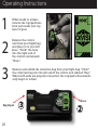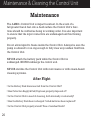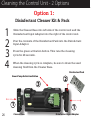
1
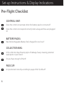
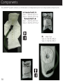
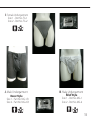
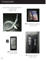
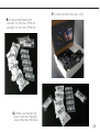
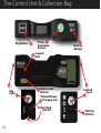
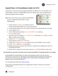
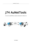
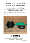
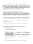
AMXD
®
Advanced Mission Extender Device
User & Maintenance Guide
WARRANTY
Omni warrants its system to the original purchaser, against defects in
material and workmanship for a period of one year from the date of
original purchase and will at our option, replace or repair defective
parts without charge. Omni will, replace or repair any part found to
be defective upon inspection by Omni. The purchaser will be responsible for freight to Omni. Omni will be responsible for freight, via
UPS Ground, to purchaser after repairs. This warranty does not apply
in the event of misuse or abuse or failure by the user to maintain the
system in accordance with Omni instructions or as a result of unauthorized alterations or repairs. Damage occurring during transit is not
covered by this warranty. No other warranty expressed or implied
shall apply and in no event shall Omni be liable for consequential
economic damage or consequential damage to property.
OMSI DISCLAIMER
Buyer assumes all risk and liability whatsoever from the installation
and use of Omni products. Omni products are sold as bodily fluid
collection and storage devices in a seated position and should not be
relied upon as protection from bodily fluids exposure to the body,
clothing or other items such as flight deck equipment. Omni assumes
no liability for injury, loss, incidental or consequential damages in the
event of an accident.
AMXD
®
Advanced Mission Extender Device
User & Maintenance Guide
Table of Contents
Table of Contents...........................................................................................................6
Conventions Used in this Guide............................................................................7
Set-up Instructions & Display Indications........................................................8
Components....................................................................................................................10
Control Unit & Collection Bag...............................................................................16
Male Cup & Undergarment Fitting & Sizing.................................................18
Female Pad & Undergarment Fitting & Sizing............................................20
Non-Rechargeable Battery Pack..........................................................................22
Rechargeable Battery Pack & World Power Kit............................................23
Attaching the Battery Pack.....................................................................................24
Operating Instructions..............................................................................................26
Maintenance & Cleaning the Control Unit....................................................30
Conventions Used in this Guide
16 16
IMPORTANT OR YELLOW TEXT
All instructions will be labeled with a large number,
the illustration which corresponds to that step will be
labeled with a small number in a circle
Indicates an item of particular importance
Indicates a direction of travel
Indicates a connection between a caption to an illustration or photo
Indicates rotation
Indicates a disposable system component
Indicates a system component specific to female
aircrew
Indicates a system component specific to male aircrew
Indicates a system component that is machine washable
Set-up Instructions & Display Indications
Pre-Flight Checklist:
CONTROL UNIT:
Does the control unit activate when the battery pack is connected?
Does the control unit respond correctly when a bag and hose are plugged
in?
BATTERY PACKS:
Was the Rechargeable Battery Pack charged for one hour?
COLLECTION BAG:
Is the collection bag showing signs of damage, heavy creasing, potential
weak spots or punctures?
Do you have enough of them?
PAD/CUP:
Is it positioned correctly according to pages 18 & 19, 20 & 21?
Battery connected, Hose connected,
ready to connect
ready to connect
Bag
Hose and Bag
Ready to
urinate
Liquid pump
running
Bag connected, ready to
connect Hose
Replace
Battery Pack
Bag and Hose
connected, Cup inflating
Have Control
Unit Serviced
Components
The AMXD™ system utilizes a combination of disposable and non-disposable components.
A. Control Unit Part No. SCU-10
B. Rechargeable Battery Pack
Part No.SCU-RBP
C. Non-Rechargeable Battery Pack
Part No. SCU-ABP
D. Power Unit Part No. MWS122500UC
F. Collection Bag
Part No.
CB-10 - 800ML
CB-12 - 1200ML
CB-16 - 1600ML
E. World Power Adaptors Part No.
AMXD-OMSI-EUR
AMXD-OMSI-AUS
AMXD-OMSI-UK
Components
The AMXD® system utilizes a combination of disposable and non-disposable components.
G. Female Pad F-15
Size 1 - Part No. IFP-15-1
Size 2 - Part No. IFP-15-2
Female Pad F-16
Size 1 - Part No. IFP-16-1
Size 2 - Part No. IFP-16-2
H.
Male Cup
Size 2 - Part No. IMC-2
Size 3 - Part No. IMC-3
10
I. Female Undergarment Size 1 - Part No. FG-1
Size 2 - Part No. FG-2
J. Male Undergarment
Boxer Style
Size 1 - Part No. MG-1-B
Size 2 - Part No. MG-2-B
K. Male Undergarment
Brief Style
Size 1 - Part No. MG-1
Size 2 - Part No. MG-2
11
Components
L. Field Cleaner Output/Input Hose Kit
Part No. CCU-20
Part No. CCU-21
M. User & Maintenance Manual
Part No. UM_V3
N. Disinfecting Pack
Part No. SDC-20
12
O. Disinfectant Cleaner Kit
Part No. CCU-10
P. Control Unit Kit Part No. CSK
R. Female Pad Starter Kit
Aircraft 15 Part No. IFPSK-15
Aircraft 16 Part No. IFPSK-16
Q. Male Cup Starter Kit
Size 1 Part No. IMCSK-1
Size 2 Part No. IMCSK-2
13
The Control Unit & Collection Bag
Bag Release
Pump
Activation
Button
Pad/Cup
Release
Lanyard
Hole
Bag
Input
Battery Lock
Release
External Power/
Charging Jack
Battery Pack
Contacts
14
Cup/Pad
Input
Pad/Cup
inflation
The AMXD® Collection Bag is a
DISPOSABLE system component.
It is intended for a single use.
On extended missions, more
than one bag may be used.
The Collection Bag contains
super absorbent polymers which
gels liquid on contact. The
standard bag is designed to hold
25 ounces (800) ml of liquid.
Connection Nozzle
(fits into the control unit in one direction)
Snap the bag open at the
white adhesive holders
15
Male Cup & Undergarment Fitting & Sizing
For correct sizing of the Male Undergarment:
1
2
3
Choose Size 1 for waist size between 30”-34”
Choose Size 2 for waist size between 36”-40”
Prior to flight, locate the opening on the inside of the undergarment.
Insert the cup into the undergarment through the velcro opening,
ensuring that the white foam ring on the Cup is extending through
the opening on the inside of the undergarment. The Foam Ring acts
as a “button” and holds the cup and undergarment together as a
functional unit.
Insert the male member through the white foam ring. Make sure the
Cup hose is facing front and to the right. When correctly worn, the
foam ring will be snug against the pelvis and the bottom of the cup
should not be folded or pinched.
Attach the Cup/Pad hose Velcro end to
the Velcro patch on the front of the undergarment or keep the hose external
to each suit except just under the first
layer. Dispose of the Male Cup after
your mission.
Important
Foam Ring for
male member
Make sure the cup hose is just under the first layer of gear.
16
Hose
Nozzle (connects to Control Unit)
1
1
Opening inside the Undergarment
2
Velcro Opening for inserting Cup
3
Foam Ring of the Cup extending through the Undergarment.
17
Female Pad & Undergarment Fitting & Sizing
For correct sizing of the Female Undergarment:
1
2
3
Choose Size 1 for sizes normally 6 and below.
Choose Size 2 for sizes normally 7 and above.
Prior to flight, locate the blue pick-up hole in the Pad. Make sure
when seated in the ejection seat, the blue hole is located at the
lowest point. This is crucial for the AMXD® System to function
properly. It is very important that this be determined and tested
on the ground, prior to flight.
Place the Pad into the undergarment with the hose in the front
and to the right. Use the adhesive strip located on the underside
of the Pad. Attach the Cup/Pad hose Velcro end to the Velcro
patch on the front of the undergarment or keep the hose external
to each suit except just under the first layer.
The Pad’s inflatable collection area should completely cover
the gluteal fold in the back, and extend forward of the female
anatomy, just below the bikini line. Wings should hang down
on both sides and the undergarment should hold the pad snugly
against the body. Dispose of the Female Pad after your mission.
Important
Make sure the pad hose is just under the first layer of gear.
18
1
The Blue Pickup Hole MUST
BE located
at the lowest
point in the
ejection seat.
Blue Pick-up Hole
Top of
Gluteal Fold
To use the AMXD® system during menstruation,
female aircrew should use a modified tampon
WITH A SHORTENED EXTRACTION STRING.
Back
Pad
Hose
3
Front
21
Non-Rechargeable Battery Pack
INSTALLING THE AAA ALKALINE BATTERIES:
Remove the battery pack’s cover by pushing your thumb
down on the gray button towards the direction of the arrow
and sliding it forward. Insert the AAA batteries according
to the polarity guide on the battery pack.
Important
The AAA Alkaline Battery
Pack will run for three 1-minute cycles before the batteries need to be replaced.
Cover
Release
16
Power
Contact
Attachment
Guide
Rechargeable Battery Pack & World Power Kit
CHARGING THE RECHARGEABLE BATTERY PACK:
The rechargeable battery pack requires an initial 1 hour
charge in the charger unit prior to use in flight. Plug the
charger into a wall outlet and the charger output connector into the control unit. This can be done with or without
the cleaner base in place. After approximately 400 charge
cycles, the display screen “service battery” will indicate
it is time to replace the Rechargeable Battery Pack.
Important
The Rechargeable Battery Pack will run for twelve
1-minute cycles before needing to be recharged.
WORLD POWER KIT:
Three international adaptors are provided to accommodate
overseas power outlets (Australian, European & Britain).
17
Attaching the Battery Pack
Slide and *click* the battery pack onto the bottom of the
control unit. If you press the green button, you will see
“OMSI” in the display. To remove the battery pack, press
the tan battery lock button and slide the battery pack off.
Green Pump Activtion Button
Battery Pack
Lock Button
18
1
100%
charge
50%
charge
Low Battery
replace or
recharge
When a unit is left unused for approximately 10 minutes
with a battery pack attached, it will enter ‘sleep mode’.
To reactivate, press the green pump activation button.
The control unit may also be powered
by an optional 12v vehicle adapter.
19
Operating Instructions
1
2
3
When ready to urinate
remove the cup/pad hose
form just inside your top
layer of gear.
Remove the control
unit from your flight bag
and place it on your left
knee. *Click* the hose
into the right end of
the control unit labeled
“Hose”.
Remove and unfold the collection bag from your flight bag .*Click*
the collection bag into the left end of the control unit labeled “Bag”.
When both ends are properly connected, the cup/pad will automatically begin to inflate.
Bag Input
20
3
Hose
2
Operating Instructions
4
4
As the cup/pad begins
to inflate, the display
air graph triangle will
fill black. Once filled,
the system is ready for
urination.
5
Push and HOLD the green
pump button. Begin to urinate. The green button must
be held during the entire
time of urination. The pump
will draw urine from the cup/
pad into the collection bag.
0%
50%
100%
5
Green Pump Activation Button
21
Operating Instructions
6
6
As liquid is pumped into the bag, the
liquid pump symbol will turn black
and the center symbol will rotate.
After urination is complete, release
the green pump activation button. The
pump will continue to run for an additional 20 seconds, clearing the tubes.
DO NOT DISCONNECT ANYTHING UNTIL THE PUMP STOPS RUNNING.
7
22
When the liquid pump symbol stops
rotating and becomes clear, this will
indicate the pump has stopped.
7
8
Unplug the collection bag from the
control unit by pressing the
Bag Release Button.
9
Unplug the cup/pad hose from
the control unit by pressing the
Cup/Pad Release Button. The
cup/pad will automatically deflate. You will also notice that
there could be a small amount
of some residual urine in the
cup or pad, but this is normal.
10
Stowe away the Control Unit and
Collection Bag. Be sure the cup/
pad hose is tucked or secured.
Bag Release
Cup/Pad Hose Release
9
8
23
Maintenance & Cleaning the Control Unit
Maintenance
The AMXD® Control Unit is impact resistant. In the event of a
fall greater than 2 feet onto a hard surface the Control Unit’s functions should be verified as being in working order. It is also important
to ensure that the input connectors are undamaged and functioning
properly.
Do not allow liquid to freeze inside the Control Unit. Always be sure the
pump is allowed to run ong enough to fully clear any residual fluid from
the Control Unit.
NEVER attach the battery pack while the Control Unit is
submerged. NEVER submerge the control unit.
NEVER sterilize the Control Unit with microwaves or with steam-based
cleaning systems.
After Flight
• Is the Battery Pack disconnected from the Control Unit?
• Has Collection Bag(s) & Pad/Cup been properly disposed of?
• Is the Control Unit in need of cleaning, both internally or externally?
• Has the Battery Pack been recharged ? AAA batteries been replaced?
• Is the Control Unit properly stored? Free of residual fluids?
24
Cleaning the Control Unit:
2 Options
The AMXD® Control Unit is a vital system component because it will
be exposed to a variety of environments and conditions (including
combat). It should be cleaned and checked regularly. If stored for an
extended period of time, it is important that the device be occasionally powered up and functions checked. Additionally, connection
inputs should be exercised by actually connecting a pad/cup hose and
a collection bag.
The AMXD® Control Unit is water resistant, NOT WATER PROOF,
NEVER submerge the control unit. In the event it is completely submerged, it must be returned to OMSI for recertification before use.
NEVER clean with bleach. This applies to the internal plumbing, and
the exterior case. A commercial anti-bacterial cleaner may be used on
the exterior.
If the Disinfectant Pack is unavailable, and the internal plumbing
needs cleaning, a weak 10 to 1 solution (10 parts water and 1 part
anti-bacterial agent) may be used.
NEVER clean the control unit with dish/laundry detergent, alcohol, or
petroleum based solvents.
25
Cleaning the Control Unit - 2 Options
Option 1:
Disinfectant Cleaner Kit & Pack
1
2
3
4
Slide the Cleaner Base into left side of the control unit and the
Disinefectant Input Adapter into the right of the control unit.
Pour the contents of the Disinfectant Pack into the Disinfectant
Input Adaptor.
Press the green activation button. This runs the cleaning
cycle for 20 seconds.
When the cleaning cycle is complete, be sure to drain the used
cleaning fluid from the Cleaner Base.
Disinfectant Pack
Green Pump Activation Button
3
1
26
Cleaner Base
2
1
Disinfectant Input Adaptor
Option 2:
Field Cleaner Input/Output Hoses
1
2
3
4
After attaching a battery pack, attach input cleaner hose in the
same manner as the cup/pad hose. Then, attach the cleaner output hose in the same manner as the collection bag.
Open the Disinfectant Pack, and pour the contents into a bucket
of warm soapy water. Place the end of the hose attached to cup/
hose input into the container of warm soapy water. An
empty bucket is recommended to capture the water pumped
through the control unit.
Press the green pump activation button allowing water to pump
for 3 minutes. Place the end of the hose attached to cup/pad
hose input into the container of clean water.
To clean the outer casing of the control unit use a washcloth and
warm soapy water.
27
© 2007 Omni Medical Systems, Inc. - Made in USA Version 3
Omni Medical Systems, Inc. - 115 Catamount Drive - Milton, Vermont 05468
www.omnimedicalsys.com - Toll Free Phone: 1 . 888 . 799 . AMXD (2693)