1
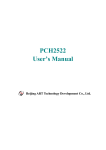
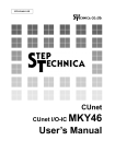
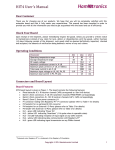
PCI-D64HU User’s Manual Warranty All products manufactured by ICP DAS are warranted against defective materials for a period of one year from the date of delivery to the original purchaser. Warning ICP DAS assume no liability for damages consequent to the use of this product. ICP DAS reserves the right to change this manual at any time without notice. The information furnished by ICP DAS is believed to be accurate and reliable. However, no responsibility is assumed by ICP DAS for its use, nor for any infringements of patents or other rights of third parties resulting from its use. Copyright Copyright 2009 by ICP DAS. All rights are reserved. Trademark The names used for identification only may be registered trademarks of their respective companies. PCI-D64HU User’s Manual (Ver.1.0, Dec/2009) 1 Table of Contents 1. 2. Introduction ....................................................................................................................... 3 1.1. General Description ............................................................................................................. 3 1.2. Features................................................................................................................................. 4 1.3. Block Diagram...................................................................................................................... 5 1.4. Specifications ........................................................................................................................ 6 1.5. Product Check List .............................................................................................................. 7 Hardware Configuration................................................................................................... 8 2.1. Board Layout........................................................................................................................ 8 2.2. Switch Setting ....................................................................................................................... 9 2.3. Pin Assignment ................................................................................................................... 10 2.4. Operation Theory................................................................................................................11 2.5. Timing Characteristic........................................................................................................ 14 PCI-D64HU User’s Manual (Ver.1.0, Dec/2009) 2 1. Introduction 1.1. General Description The PCI-D64HU card provides 40 MB/s High-Speed 32-CH Digital Input and 32-CH Digital Output.PCI-D64HU is a high-speed digital I/O card consisting of 32 digital input channels and 32 digital output channels. High-performance designs make this card perfect for high-speed data transfer and pattern generation applications. The PCI-D64HU has the Card ID switch on board. Users can set Card ID on a board and recognize the board by the ID via software when using two or more PCI-D64HU cards in one computer. The PCI-D64HU performs high-speed data transfer by bus-mastering DMA via 32-bit PCI bus. The maximum data transfer rate can be up to 40 MB per second. Several digital I/O transfer modes are supported, such as direct programmed I/O control, timer pacer control, external clock mode and handshaking mode. It is a reliable and cost-effective connection interface that works on your computer system to control high-speed peripherals. PCI-D64HU User’s Manual (Ver.1.0, Dec/2009) 3 1.2. Features The following is a list of general features for the PCI-D64HU. Check section 1.5 for more details. Support 32-bit, 33 MHz Universal PCI bus 32-CH 5V TTL Digital Inputs and 32-CH 5V TTL Digital Outputs 2-CH Bus Mastering Scatter/Gather DMA Data Transfer Rate up to 40 MB/s for Each Channel Support 4 Data Transfer Modes Direct Program Control Mode Internal Timer Pacer Mode External Clock Mode (DI Only) Handshaking Mode On Board 1 k/2 k DWORD FIFO for DI/DO Respectively DO FIFO Support Ring Buffer Mode -- No Bus Loading in Repetitive Pattern Card ID function 1.3. Generation Application Programmable Input Digital Filter for All Input Signals Including Handshaking and Trigger Signals PCI-D64HU User’s Manual (Ver.1.0, Dec/2009) 4 1.4. Block Diagram PCI-D64HU User’s Manual (Ver.1.0, Dec/2009) 5 1.5. Specifications Model Name Digital Input Channels Compatibility Input Voltage Handshaking Signals Digital Output Channels Compatibility Output Voltage Output Capability PCI-D64HU 32 5 V/TTL Logic 0: 0.8 V max. Logic 1: 2.0 V min. I_REQ input , I_ACK output , I_TRG input 32 5 V/TTL Logic 0: 0.55 V max. Logic 1: 2.0 V min. Sink: 64 mA @ 0.55 V Source: -32 mA @ 2.0 V O_REQ output, O_ACK input, O_TRG output 40 MB/sec for DI and DO simultaneously (max.) Handshaking Signals Transfer Speed Programmable Digital Filter Applicable Signals All input signals (including 32 DI signals, I_REQ, I_TRG and O_ACK) Max. removable noise width (1 ~ 127) x 25 ns Programmable Pulse Extender Applicable Signals O_REQ Pulse width (2 ~ 256) x 25 ns Timer/Counter Channels 3 Resolution 16-bit Input Frequency 2.5 ~ 20 MHz Timer 0 Clock source of DI Timer 1 Clock source of DO Timer 2 Base clock of Timer 0 and Timer 1 Interrupt Sources O_ACK, I_REQ, Timer 0, Timer 1 and Timer 2 On Board FIFO 1 k DWORD (32-bit) DI / DO 2 k DWORD (32-bit) Size in Ring Buffer Mode 2 ~ 2 k DWORD (32-bit), DO only General Bus Type Universal PCI, 32-bit, 33 MHz Card ID Yes (4-bit) Female DB37 x 1 I/O Connector 40-pin Box header x 1 Dimensions (L x W x D) 120 mm x 105 mm x 22 mm Power Consumption 200 mA @ +5 V typical (output no load) Operating Temperature 0 ~ 60 °C Storage Temperature -20 ~ 70 °C Humidity 5 ~ 85% RH, non-condensing PCI-D64HU User’s Manual (Ver.1.0, Dec/2009) 6 1.6. Product Check List In addition to this manual, the package includes the following items: One PCI-D64HU card One ICP-DAS software CD-ROM One Quick Start Guide It is recommended to read the Quick Start Guide first. The following important information will be given in the Quick Start Guide: 1. Where you can find the software driver & utility 2. How to install software & utility 3. Location of the diagnostic program 1.7. Ordering Information Ordering Information: PCI-D64HU: 40 MB/s High-speed 32-CH DI and 32-CH DO Universal PCI DIO Card (RoHS). Includes one CA-4037W cable and two CA-4002 D-Sub connectors Accessories: CA-3710: DB-37 Male-Male D-sub cable 1M (45º) CA-3710DM: DB-37 Male-Male D-sub cable 1M (180º) DN-37: DIN-Rail Mounting 37-pin Connector (Pitch=5.08mm) DN-37-381: DIN-Rail Mounting 37-pin Connector (Pitch=3.81mm) DB-37: Directly connect signal to D-Sub 37-pin connector Attention! If any of these items are missing or damaged, please contact your local field agent. Save the shipping materials and carton in case you want to ship or store the product in the future. PCI-D64HU User’s Manual (Ver.1.0, Dec/2009) 7 2. Hardware Configuration 2.1. Board Layout Item CON1 CON2 SW1 JP1 Description I/O connector (37-pin D-Sub female) I/O connector (40-pin Box Header) Card ID switch Factory reserved PCI-D64HU User’s Manual (Ver.1.0, Dec/2009) 8 2.2. Card ID Switch Setting SW1: Card ID Switch The SW1 switch is used to set the card ID. The value is from 0 to 15. Please refer to table below for details. Card ID ON 1 2 3 Default 4 0(Default) 1 2 3 4 5 6 7 8 9 10 11 12 13 14 15 Switch Setting (On = 1) 1 2 3 4 0 0 0 0 1 0 0 0 0 1 0 0 1 1 0 0 0 0 1 0 1 0 1 0 0 1 1 0 1 1 1 0 0 0 0 1 1 0 0 1 0 1 0 1 1 1 0 1 0 0 1 1 1 0 1 1 0 1 1 1 1 1 1 1 PCI-D64HU User’s Manual (Ver.1.0, Dec/2009) 9 2.3. Pin Assignment The PCI-D64HU has one 37-pin D-Sub connector (CON1) and one 40-pin pin header (CON2). Please refer figure below for the pin assignment of CON1 and CON2 Signal Name DIx DOx GND +5V I_TRG I_REQ I_ACK O_TRG O_REQ O_ACK Description Digital input channel x Digital output channel x Ground of all signals +5V power output (Max. 400 mA per pin) Trigger input to start DI sampling Request input for DI handshaking Acknowledge output for DI handshaking Trigger output controlled by software Request output for DO handshaking Acknowledge input for DO handshaking Direction Input Output Power Power Input Input Output Output Output Input CON2 CON1 I_TRG GND DO15 DO14 DO13 DO12 DO11 DO10 DO9 DO8 DO7 DO6 DO5 DO4 DO3 DO2 DO1 DO0 37 36 35 34 33 32 31 30 29 28 27 26 25 24 23 22 21 20 19 18 17 16 15 14 13 12 11 10 9 8 7 6 5 4 3 2 1 I_REQ I_ACK +5V DI15 DI14 DI13 DI12 DI11 DI10 DI9 DI8 DI7 DI6 DI5 DI4 DI3 DI2 DI1 DI0 N.C. N.C. O_TRG GND DO31 DO30 DO29 DO28 DO27 DO26 DO25 DO24 DO23 DO22 DO21 DO20 DO19 DO18 DO17 DO16 40 38 36 34 32 30 28 26 24 22 20 18 16 14 12 10 8 6 4 2 39 37 35 33 31 29 27 25 23 21 19 17 15 13 11 9 7 5 3 1 N.C. O_REQ O_ACK +5V DI31 DI30 DI29 DI28 DI27 DI26 DI25 DI24 DI23 DI22 DI21 DI20 DI19 DI18 DI17 DI16 PCI-D64HU User’s Manual (Ver.1.0, Dec/2009) 10 2.4. Operation Theory The PCI-D64HU support 4 data transfer modes, they are direct programmed I/O control, timer pacer control, external clock mode and handshaking mode. This chapter descript the detailed operation of these 4 data transfer modes. Direct Program Control Mode The status of digital inputs and digital outputs can be directly accessed by I/O port access. The I/O port address is assigned by system BIOS, please refer to the function reference manual for more detailed description. Internal Timer Pacer Mode There are three 16-bit timers on board. Timer#0 is for DI update and Timer#1 is for DO update. Both Timer#0 and Timer#1 can be optionally cascaded with Timer#2 for slower timer pacer generation. The base clock of all timers can be programmed from 20 MHz to 2.5 MHz (40 MHz / n; where n = 2 ~ 16). For digital input, the input data will be saved into DI FIFO after a timer pacer pulse is generated. When the DI FIFO is not empty, the saved data will be automatically transferred to the main memory of computer system by the bus mastering DMA controller. For digital output, the state of output pins will be updated by the data in DO FIFO after a timer pacer pulse is generated. When the DO FIFO is not full, data in the main memory will be automatically transferred to the DO FIFO by the bus mastering DMA controller. External Clock Mode (DI Only) The digital input is clocked by external strobe, which is from Pin 19 (I_REQ) of CON1. PCI-D64HU User’s Manual (Ver.1.0, Dec/2009) 11 The input data will be saved into DI FIFO after a strobe is generated. When the DI FIFO is not empty, the saved data will be automatically transferred to the main memory of computer system by the bus mastering DMA controller. 1. Digital Input data is ready and an I_REQ signal is generated by external device. 2. Digital input data is saved to FIFO. 3. If the FIFO is not empty and PCI bus is not occupied, the data will be transferred to main memory. Handshaking Mode The PCI-D64HU also supports handshaking data transfer mode. The data transfer rate is controlled by REQ and ACK signals to guarantee no data loss. The operation of DI Handshaking Digital Input Data 1 I_REQ 2 ( Input Signal ) 4 Latch Digital Input Data I_ACK ( Output Signal ) 3 Digital Input FIFO PC’s Main Memory 5 Bus mastering DMA data Transfer 1. Digital Input data is ready. 2. An I_REQ signal is generated by external device. 3. Digital input data is saved to FIFO. 4. An I_ACK signal is generated and sent to the external device. 5. If the FIFO is not empty and PCI bus is not occupied, the data will be transferred to main memory. The operation of DO Handshaking PCI-D64HU User’s Manual (Ver.1.0, Dec/2009) 12 Digital Output Data 4 3 O_REQ ( Output signal ) Move Data to Digital Output O_ACK ( Input signal ) 5 2 Digital Output FIFO PC’s Main Memory 1 Bus mastering DMA data Transfer 1. Digital output data is moved from PC’s memory to DO FIFO by bus mastering DMA data transfer. 2. Move output data from FIFO to digital output circuit. 3. Output data is ready. 4. An O_REQ signal is generated and sent to the external device. 5. After an O_ACK is captured, steps 2-5 will be repeated. ** If the FIFO is not full, the output data is moved form PC‘s main memory to FIFO automatically. DO Ring Buffer Mode The ring buffer is managed in hardware level and the size of the ring buffer can be set by user. When the DO FIFO is set as ring buffer mode, the last buffer of the DO buffer will be chained with the first buffer. No bus loading is required which makes PCI-D64HU perfect for repetitive pattern generation application. PCI-D64HU User’s Manual (Ver.1.0, Dec/2009) 13 2.5. Timing Characteristic Characteristic of Input Digital Filter The digital filter is applicable for all DI signals, IREQ, ITRG and OACK. The maximum removable noise width can be programmed from (1~127) x 25ns. Where n=1~127 Characteristic of Output Pulse Extender in Timer Pacer Mode System CLK 40MHz O_REQ ( Output Signal ) tL DO0 ~ DO31 ( Output Signal ) Valid Data tS tH 25ns <= tS <= (2^(n+1)) * 25ns tL >= tH = (2^(n+1)) * 25ns (2^(n+1)) * 25ns Notes: n = 0~7 PCI-D64HU User’s Manual (Ver.1.0, Dec/2009) 14 Characteristic of IREQ in External Clock Mode IREQ Rising Edge Trigger: IREQ Falling Edge Trigger: PCI-D64HU User’s Manual (Ver.1.0, Dec/2009) 15 Characteristic of DI Handshaking Mode Characteristic of DO Handshaking Mode PCI-D64HU User’s Manual (Ver.1.0, Dec/2009) 16