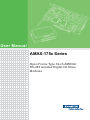
1
User Manual AMAX-175x Series Open Frame Type 32-ch AMONet RS-485 Isolated Digital I/O Slave Modules Copyright The documentation and the software included with this product are copyrighted 2012 by Advantech Co., Ltd. All rights are reserved. Advantech Co., Ltd. reserves the right to make improvements in the products described in this manual at any time without notice. No part of this manual may be reproduced, copied, translated or transmitted in any form or by any means without the prior written permission of Advantech Co., Ltd. Information provided in this manual is intended to be accurate and reliable. However, Advantech Co., Ltd. assumes no responsibility for its use, nor for any infringements of the rights of third parties, which may result from its use. Acknowledgements AMONet, AMAX-1752, AMAX-1754 and AMAX-1756 are trademarks of Advantech Inc. Intel and Pentium are trademarks of Intel Corporation. Microsoft Windows and MS-DOS are registered trademarks of Microsoft Corp. All other product names or trademarks are properties of their respective owners. Product Warranty (2 years) Advantech warrants to you, the original purchaser, that each of its products will be free from defects in materials and workmanship for two years from the date of purchase. This warranty does not apply to any products which have been repaired or altered by persons other than repair personnel authorized by Advantech, or which have been subject to misuse, abuse, accident or improper installation. Advantech assumes no liability under the terms of this warranty as a consequence of such events. Because of Advantech’s high quality-control standards and rigorous testing, most of our customers never need to use our repair service. If an Advantech product is defective, it will be repaired or replaced at no charge during the warranty period. For outof-warranty repairs, you will be billed according to the cost of replacement materials, service time and freight. Please consult your dealer for more details. If you think you have a defective product, follow these steps: 1. Collect all the information about the problem encountered. (For example, CPU speed, Advantech products used, other hardware and software used, etc.) Note anything abnormal and list any onscreen messages you get when the problem occurs. 2. Call your dealer and describe the problem. Please have your manual, product, and any helpful information readily available. 3. If your product is diagnosed as defective, obtain an RMA (return merchandize authorization) number from your dealer. This allows us to process your return more quickly. 4. Carefully pack the defective product, a fully-completed Repair and Replacement Order Card and a photocopy proof of purchase date (such as your sales receipt) in a shippable container. A product returned without proof of the purchase date is not eligible for warranty service. 5. Write the RMA number visibly on the outside of the package and ship it prepaid to your dealer. Part No. 2003A17500 Edition 1 Printed in Taiwan November 2012 AMAX-175x Series User Manual ii Declaration of Conformity CE This product has passed the CE test for environmental specifications when shielded cables are used for external wiring. We recommend the use of shielded cables. This kind of cable is available from Advantech. Please contact your local supplier for ordering information. Technical Support and Assistance 1. 2. Visit the Advantech web site at www.advantech.com/support where you can find the latest information about the product. Contact your distributor, sales representative, or Advantech's customer service center for technical support if you need additional assistance. Please have the following information ready before you call: – Product name and serial number – Description of your peripheral attachments – Description of your software (operating system, version, application software, etc.) – A complete description of the problem – The exact wording of any error messages Packing List Before setting up the system, check that the items listed below are included and in good condition. If any item does not accord with the table, please contact your dealer immediately. In addition to this User Manual, the package should also include the following items: AMAX-175x Series Slave Module Quick Start User Manual User Manual iii AMAX-175x Series User Manual AMAX-175x Series User Manual iv Contents Chapter Chapter 1 Introduction..........................................1 1.1 1.2 Features .................................................................................................... 2 Specifications ............................................................................................ 2 1.2.1 General ......................................................................................... 2 1.2.2 Isolated Digital Input ..................................................................... 2 1.2.3 Isolated Digital Output................................................................... 3 1.2.4 Environment.................................................................................. 3 2 Hardware Functionality .......................5 2.1 2.2 2.3 2.4 2.5 2.6 2.7 2.8 2.9 Figure 2.1 Top View..................................................................... 6 Figure 2.2 Middle View ................................................................ 6 Figure 2.3 Bottom View ............................................................... 7 Figure 2.4 Side View.................................................................... 7 Module Power Connector(CN1) ................................................................ 8 External Power Input Connector(CN2)...................................................... 8 External Power Output Connector(CN3)................................................... 8 Board ID Switch (SW1) ............................................................................. 9 Configuration Setting (SW2) ..................................................................... 9 2.5.1 Baud-Rate Setting......................................................................... 9 2.5.2 TUD............................................................................................... 9 2.5.3 TMD ............................................................................................ 10 Terminal Resistor .................................................................................... 10 LED Definition ......................................................................................... 10 2.7.1 AMAX-1752................................................................................. 11 2.7.2 AMAX-1754................................................................................. 11 2.7.3 AMAX-1756................................................................................. 11 Pin Definitions ......................................................................................... 12 2.8.1 AMAX-1752 (32 DI)..................................................................... 12 2.8.2 AMAX-1754 (32 DO)................................................................... 13 2.8.3 AMAX-1756 (16 DI 16DO) .......................................................... 13 Signal Connection ................................................................................... 14 2.9.1 Isolated Digital Output................................................................. 14 2.9.2 Isolated Digital Input ................................................................... 14 v AMAX-175x Series User Manual AMAX-175x Series User Manual vi Chapter 1 1 Introduction This chapter gives an overview of the product features, and specifications for AMAX-175x Series. Sections include: Features Specifications Products in the AMAX-175x Series are used to increase the number of digital input/ output channels for an AMONet RS-485 distributed motion control network. These extension slave modules connect serially by a simple and affordable Cat.5 LAN cable, reducing the wiring between driver and controller. This is very suitable for highly integrated machine automation applications. 1.1 Features Communication baud rate, 2.5Mbps, 5Mbps, 10Mbps and 20Mbps are supported and switchable Onboard screw terminal for direct wiring 2,500 VRMS Isolation voltage Suitable for DIN-rail mounting Board ID is switchable Easily visible LED indicators on board to do diagnosis 1.2 Specifications 1.2.1 General BUS TYPE AMONet RS-485 Certifications CE, FCC Class A Connectors (1) RJ-45 x 2 are for communication port (2) I/O points use screw terminal type connector LED Indicators Power, Run, Status, Isolated Digital I/O Power Consumption 600mW typical, 2 W max. Power Supply for Module VS: 24 Vdc ± 10% Power Supply for Digital Input/Output VEX: 10-30 Vdc 1.2.2 Isolated Digital Input Channels AMAX-1752: 32 DI AMAX-1756: 16 DI Input type Dry contact Input voltage △ V *= 0~3v(Low Level) / 10~30v(High Level) (30Vdc Max) Input resistance 3.2K Input current 2mA Min. Input delay 100us Max. (Isolation delay) Input Isolation 2500Vdc *NOTE: △V=| IDICOMx - IDIx |. For pin assignment definition, please refer to 2.6.1 to 2.6.3 for details. For signal connection, please refer to 2.7.2. AMAX-175x Series User Manual 2 AMAX-1754: 32 DO AMAX-1756: 16 DO Output type Sink(NPN) (open collector Darlington) Output control voltage 35Vdc Max. Output sink current 500mA Max. (for each channel) Output delay 250us Max. (photo coupler delay) Output Isolation 2500Vdc 1.2.4 Environment Operating Humidity 5 ~ 95 % RH, non-condernsing (refer to IEC 68-2-3) Operating Temperature 0 ~ 65° C (refer to IEC 68-2-1,2) (32 ~ 149° F) Storage Temperature -25 ~ 85° C (-13 ~ 185° F)) 3 AMAX-175x Series User Manual Introduction Channels Chapter 1 1.2.3 Isolated Digital Output AMAX-175x Series User Manual 4 Chapter 2 2 Hardware Functionality This chapter shows the hardware functionality of AMAX-175x Series. Sections include: PCB Board Layout Power Connector AMONet Interface BoardID Switch Configuration Setting LED Definition Pin Definition Signal Connection Field Wiring Considerations AMAX-175x series is open frame type AMONET I/O modules which has on-board connectors for direct wiring and LED indicators to show the status. Here is the product dimension information: Figure 2.1 Top View Figure 2.2 Middle View Note! The height does not include the male connector. The height of the male connector is 9mm. AMAX-175x Series User Manual 6 Chapter 2 Hardware Functionality Figure 2.3 Bottom View Figure 2.4 Side View 7 AMAX-175x Series User Manual 2.1 Module Power Connector(CN1) Pin Descrption 1 +VS input 24 Vdc ± 10% 2 GND for VS 3 Field Ground 2.2 External Power Input Connector(CN2) Pin Descrption 1 +VEX (10-30 Vdc) 2 GND for VEX 3 Field Ground 2.3 External Power Output Connector(CN3) Pin Descrption 1~3 +VEX (10-30 Vdc) 4~6 GND for VEX AMAX-175x Series User Manual 8 Label ON OFF 1 DN5 1 0 2 DN4 1 0 3 DN3 1 0 4 DN2 1 0 5 DN1 1 0 6 DN0 1 0 Note: Node Number=32xDN5+16xDN4+8xDN3+4xDN2+2xDN1+DN0. Default Setting: All the switches are in OFF status. 2.5 Configuration Setting (SW2) Switch Label 1 SPD1 2 SPD0 3 TUD Time-Out Status Latch 4 TMD Specify watchdog timer time 5 BRK *For internal use only, please keep in OFF 6 Description Baud-Rate Setting N/A 2.5.1 Baud-Rate Setting SPD1 SPD0 OFF OFF 20 MHz OFF ON 10 MHz ON OFF 5 MHz ON ON 2.5 MHz 2.5.2 TUD This terminal is used to set output conditions when the watchdog timer times out. OFF The output keeps its current status. ON The output is Reset. 9 AMAX-175x Series User Manual Hardware Functionality Pin Chapter 2 2.4 Board ID Switch (SW1) 2.5.3 TMD When the interval between data packets sent from a master card (ex. PCI-1202U) is longer than the specified interval, the watchdog timer times out 20 Mbps 10 Mbps 5 Mbps 2.5 Mbps OFF 20 ms 40 ms 80 ms 160 ms ON 5 ms 10 ms 20 ms 40 ms 2.6 Terminal Resistor PIN 100 1/4W Resistor Note! 3 6 Terminal Resistor is used for the last module only. 2.7 LED Definition LED Descrption PWR Power indicator RUN Module in communication STS Communication status AMAX-175x Series User Manual 10 LED Descrption P0 (0~7) IDI0-<0~7> P1 (0~7) IDI1-<0~7> P2 (0~7) IDI2-<0~7> P3 (0~7) IDI3-<0~7> Chapter 2 2.7.1 AMAX-1752 Hardware Functionality 2.7.2 AMAX-1754 LED Descrption P0 (0~7) IDO0-<0~7> P1 (0~7) IDO1-<0~7> P2 (0~7) IDO2-<0~7> P3 (0~7) IDO3-<0~7> 2.7.3 AMAX-1756 LED Descrption P0 (0~7) IDI0-<0~7> P1 (0~7) IDI1-<0~7> P2 (0~7) IDO2-<0~7> P3 (0~7) IDO3-<0~7> 11 AMAX-175x Series User Manual 2.8 Pin Definitions 2.8.1 AMAX-1752 (32 DI) CN4 Pin1 IDI_COM0 Pin2 CN5 Pin1 CN6 CN7 IDI_COM1 Pin1 IDI_COM2 Pin1 IDI_COM3 IDI0-0 (DI0) Pin2 IDI1-0 (DI8) Pin2 IDI2-0 (DI16) Pin2 IDI3-0 (DI24) Pin3 IDI0-1 (DI1) Pin3 IDI1-1 (DI9) Pin3 IDI2-1 (DI17) Pin3 IDI3-1 (DI25) Pin4 -VEX -VEX Pin4 -VEX Pin4 -VEX Pin5 IDI0-2 (DI2) Pin5 IDI1-2 (DI10) Pin5 IDI2-2 (DI18) Pin5 IDI3-2 (DI26) Pin6 IDI0-3 (DI3) Pin6 IDI1-3 (DI11) Pin6 IDI2-3 (DI19) Pin6 IDI3-3 (DI27) Pin7 IDI_COM0 IDI_COM1 IDI_COM2 Pin7 IDI_COM3 Pin8 IDI0-4 (DI4) Pin8 IDI1-4 (DI12) Pin8 IDI2-4 (DI20) Pin8 IDI3-4 (DI28) Pin9 IDI0-5 (DI5) Pin9 IDI1-5 (DI13) Pin9 IDI2-5 (DI21) Pin9 IDI3-5 (DI29) Pin10 -VEX -VEX -VEX Pin10 -VEX Pin11 IDI0-6 (DI6) Pin11 IDI1-6 (DI14) Pin11 IDI2-6 (DI22) Pin11 IDI3-6 (DI30) Pin12 IDI0-7 (DI7) Pin12 IDI1-7 (DI15) Pin12 IDI2-7 (DI23) Pin12 IDI3-7 (DI31) Pin4 Pin7 Pin10 AMAX-175x Series User Manual Pin7 Pin10 12 CN4 CN5 CN6 CN7 +VEX Pin1 +VEX Pin1 +VEX Pin1 +VEX Pin2 IDO0-0 (DO0) Pin2 IDO1-0 (DO8) Pin2 IDO2-0 (DO16) Pin2 IDO3-0 (DO24) Pin3 IDO0-1 (DO1) Pin3 IDO1-1 (DO9) Pin3 IDO2-1 (DO17) Pin3 IDO3-1 (DO25) Pin4 -VEX Pin4 -VEX Pin4 -VEX Pin4 -VEX Pin5 IDO0-2 (DO2) Pin5 IDO1-2 (DO10) Pin5 IDO2-2 (DO18) Pin5 IDO3-2 (DO26) Pin6 IDO0-3 (DO3) Pin6 IDO1-3 (DO11) Pin6 IDO2-3 (DO19) Pin6 IDO3-3 (DO27) Pin7 +VEX Pin7 +VEX Pin7 +VEX Pin7 +VEX Pin8 IDO0-4 (DO4) Pin8 IDO1-4 (DO12) Pin8 IDO2-4 (DO20) Pin8 IDO3-4 (DO28) Pin9 IDO0-5 (DO5) Pin9 IDO1-5 (DO13) Pin9 IDO2-5 (DO21) Pin9 IDO3-5 (DO29) Pin10 -VEX Pin10 -VEX Pin10 -VEX Pin10 -VEX Pin11 IDO0-6 (DO6) Pin11 IDO1-6 (DO14) Pin11 IDO2-6 (DO22) Pin11 IDO3-6 (DO30) Pin12 IDO0-7 (DO7) Pin12 IDO1-7 (DO15) Pin12 IDO2-7 (DO23) Pin12 IDO3-7 (DO31) 2.8.3 AMAX-1756 (16 DI 16DO) CN4 CN5 CN6 CN7 Pin1 IDI_COM0 Pin1 IDI_COM1 Pin1 +VEX Pin2 IDI0-0 (DI0) Pin2 IDI1-0 (DI8) Pin2 IDO2-0 (DO16) Pin2 IDO3-0 (DO24) Pin3 IDI0-1 (DI1) Pin3 IDI1-1 (DI9) Pin3 IDO2-1 (DO17) Pin3 IDO3-1 (DO25) Pin4 -VEX Pin4 -VEX Pin4 -VEX -VEX Pin5 IDI0-2 (DI2) Pin5 IDI1-2 (DI10) Pin5 IDO2-2 (DO18) Pin5 IDO3-2 (DO26) Pin6 IDI0-3 (DI3) Pin6 IDI1-3 (DI11) Pin6 IDO2-3 (DO19) Pin6 IDO3-3 (DO27) Pin7 IDI_COM0 Pin7 IDI_COM1 +VEX +VEX Pin8 IDI0-4 (DI4) Pin8 IDI1-4 (DI12) Pin8 IDO2-4 (DO20) Pin8 IDO3-4 (DO28) Pin9 IDI0-5 (DI5) Pin9 IDI1-5 (DI13) Pin9 IDO2-5 (DO21) Pin9 IDO3-5 (DO29) Pin7 Pin10 -VEX Pin1 Pin4 Pin7 +VEX Pin10 -VEX Pin10 -VEX Pin11 IDI0-6 (DI6) Pin11 IDI1-6 (DI14) Pin11 IDO2-6 (DO22) Pin11 IDO3-6 (DO30) Pin12 IDI0-7 (DI7) Pin12 IDI1-7 (DI15) Pin12 IDO2-7 (DO23) Pin12 IDO3-7 (DO31) 13 Pin10 -VEX AMAX-175x Series User Manual Hardware Functionality Pin1 Chapter 2 2.8.2 AMAX-1754 (32 DO) 2.9 Signal Connection 2.9.1 Isolated Digital Output 2.9.2 Isolated Digital Input AMAX-175x Series User Manual 14 Chapter 2 Hardware Functionality AMAX-175x Series User Manual 15 www.advantech.com Please verify specifications before quoting. This guide is intended for reference purposes only. All product specifications are subject to change without notice. No part of this publication may be reproduced in any form or by any means, electronic, photocopying, recording or otherwise, without prior written permission of the publisher. All brand and product names are trademarks or registered trademarks of their respective companies. © Advantech Co., Ltd. 2012