1
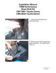
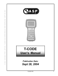
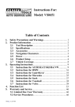
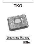
PENLOADER TOOL
UserManual
For Software Version: 2.01
The use of this apparatus is limited to legitimate and legal purposes for vehicle
maintenance, in compliance with federal and state laws and regulations.
i
Thumbwheel Setting
Operation
00
Write from memory block 0
01
Write from memory block 1
02
Write from memory block 2
03
Write from memory block 3
04
Display keys for 3key 16 bit
05
Prog file: 3key16bit
06
Prog file: 16bit
07
Prog file: 32bit
08
Prog file: 47010
09
Prog file: 34010
10
Prog file: 50020
11
Prog file: 60330
12
Prog file: 60230
13
Prog file: 33110
14
Prog file: Aa010
15
Prog file: 35090
16
Prog file: 60220
17
Prog file: 08010
18
Prog file: 50050
19
Prog file: 48020
20
Prog file: 0e010
21
Prog file: 47020
22
Prog file: 50030
23
Prog file: 50031
24
Prog file: 24020
25
Prog file: nontrans
26
Prog file: Red_Black
27
Display Red and Black keys
28 to 88
Not in use
89
Jeep Liberty 95080 PIN read
90
Nissan 05 PIN read
91
Nissan 09 PIN read
92
VW Beetle PIN read
93
Isuzu PIN read
94
Chrysler PIN read
ii
95
Restore original contents
98
Switch to THUMB 1 settings
99
Display serial number and power supply
voltage
THUMB 1 settings:
Thumbwheel Setting
Operation
00
Send memory block 0 to computer
01
Send memory block 1 to computer
02
Send memory block 2 to computer
03
Send memory block 3 to computer
04
Receive data from computer and save in
memory block 0
05
Receive data from computer and save in
memory block 1
06
Receive data from computer and save in
memory block 2
07
Receive data from computer and save in
memory block 3
08
Read and save to memory block 0
09
Read and save to memory block 1
10
Read and save to memory block 2
11
Read and save to memory block 3
12
Save last to memory block 0
13
Save last to memory block 1
14
Save last to memory block 2
15
Save last to memory block 3
99
Display serial number and power supply
voltage
iii
1
INTRODUCTION
1
2
PRODUCT FEATURES
2
3
4D QUICK RESET ORANGE DONGLE
4
4
PENLOADER OPERATION
5
4.1
General Operation
5
4.2
Visual and Audible Cues
9
4.3
Memory Blocks
11
4.4
Restore Original Contents
11
4.5
THUMB 1 Settings
12
5
THUMBWHEEL SELECTIONS IN DETAIL
14
5.1
General Operation
14
5.2
THUMB 1 Settings
36
iv
1 Introduction
The Penloader was designed to provide a tool that can be
used to program memory devices installed on circuit boards,
as well as read existing PINs. The tool is simple to use and
requires no external computers, keypad entry devices, adaptor
boards or cables.
Features of the tool are:
Small sized unit for hand held use
4 digit alpha-numeric display
Simple to use
Programming options selected through a 2 digit thumbwheel
switch
Onboard probes with spring loaded protective cover, for
programming 8 pin SOIC packages
Supports Microwire, I2C and SPI devices
Powered by rechargeable batteries or external 12V dc
supply
Provides measurement of power supply voltage (battery and
external supply)
Includes dual LED lamps to illuminate area around device to
be programmed
Audio feedback to user
Capability to read and display PIN numbers
60 second auto power off when not in use
Software is field updateable using a Windows PC and a
serial cable
4 on board memory blocks that can be used to save 4
unique user files.
Restore operation that can be used to restore contents of
last device programmed.
1
2 Product Features
Figure 1 – Penloader Unit
2
Item
Description
1
Thumbwheel selector
2
On/Off button
3
START buttons
4
4 character display
5
Neoprene grip
6
Spring probes
7
12V dc input connector
3
3 4D Quick Reset Orange Dongle
A “4D Quick Reset Orange Dongle” is included in the
Penloader package, to provide an easy method of adding a
key for the Toyota and Lexus models specified below. The
User Manual for this product is provided in Appendix A. It is
suggested that the “4D Quick Reset Orange Dongle” be
used first with the vehicles identified in the table below, and
the Penloader used if there is a problem adding a key using
the “4D Quick Reset Orange Dongle”.
Type of operation: Add key
Manufacturer(s): Toyota, Lexus (models specified in the
following table).
Make
Model
Year
Toyota
4Runner
2003 -2009
Toyota
Camry
2003-2009
Toyota
Solara
2004-2009
Toyota
Landcruiser
2003-2009
Toyota
Yaris
2005-2009
Lexus
ES 330
2004-2006
Lexus
GX 470
2003-2007
Lexus
RX 300
2004-2006
Lexus
RX 350
2007-2008
Lexus
LS 430
2004-2006
Lexus
SC 300
2002-2006
Lexus
SC 400
2002-2006
Lexus
SC 430
2002-2007
Lexus
LX 470
2003-2007
4
4 Penloader Operation
This tool provides a set of programming and PIN read
functions to help the locksmith when programming new
transponder keys and proxy.
General Operation
4.1
The basic operating procedure for using the Penloader is
as follows:
(i)
(ii)
(iii)
(iv)
(v)
(vi)
(vii)
Remove module containing memory device to
be programmed, from the vehicle, and
disassemble to provide access to the memory
device to be programmed or read.
Set thumbwheel to the required number (refer to
Table 3.1 below).
Power up the Penloader (thumbwheel must not
be set to 98 before power up).
Position the Penloader over the 8 pin memory
device ensuring that the spring probes are
making good contact with the legs on the
memory device. Where possible, a “Flash device
identifier” is specified to help locate the correct 8
pin device on the circuit board. Figure 2 below
shows how to locate pin 1 on the 8 pin memory
device. It is important that the spring probe
identified as “1”, is in contact with Pin 1 on the 8
pin memory device.
Push the START button.
The 4 character display will show status as the
programming/read operation proceeds. The
Penloader unit will also provide audio cues
during the operation (ref section 4.2 below).
On completion the display will identify whether
the programming operation was successful or
not. In the case of PIN reads, the display will
show the 4 digit PIN (and hold it for 5 seconds) if
the operation was successful.
5
Figure 2 – Locator for Pin 1
The following table shows the options that are selectable using
the thumbwheel.
6
Thumbwheel
Setting
Penloader Function
00
Write using data from memory block 0
01
Write using data from memory block 1
02
Write using data from memory block 2
03
Write using data from memory block 3
04
Displays 2 keys for use with thumbwheel setting
05
05
Lexus or Toyota 3 key file program
06
Lexus or Toyota - 16bit file program
07
Lexus or Toyota - 32bit file program
08
Toyota Prius - 47010 file program
09
Toyota Sequoia - 34010 file program
10
Lexus LS400 - 50020 file program
11
Lexus GX470 - 60330 file program
12
Lexus LX470 - 60230 file program
13
Lexus ES330 - 33110 file program
14
Toyota Camry – aa010 file program
15
Toyota 4runner - 35090 file program
16
Toyota Landcruiser - 60220 file program
17
Toyota Sienna - 08010 file program
18
Lexus LS430 - 50050 file program
7
19
Lexus RX330 - 48020 file program
20
Lexus RX330 - 0e010 file program
21
Toyota Prius - 47020 file program
22
Lexus LS430 - 50030 file program
23
Lexus LS430 - 50031 file program
24
Lexus SC430 - 24020 file program
25
Lexus or Toyota - nontrans file program
26
Honda Red/Black keys program
27
Displays 2 keys for use with thumbwheel setting
26
28 - 88
Not used
89
Jeep Liberty 95080 PIN read
90
Nissan 2005 PIN read
91
Nissan 2009 and up PIN read
92
VW Beetle 2000 PIN read
93
Isuzu 2003-2005 PIN read
94
Chrysler PIN read
95
Restore original contents
98
Switch to THUMB 1 settings
99
Displays unit serial number and power supply
voltage
Table 4.1 – Thumbwheel selection options
8
4.2
Visual and Audible Cues
When the Penloader is used to program an update into a
memory device it will provide both visual and audio cues to
the user. The following table defines these cues and their
definition. Note that all visual cues are displayed on the 4
character display.
9
Visual
Cue
Audio Cue
IDNT
Faint ticking sound,
with ticks
approximately 1
second apart
PROG
Machine gun type
sound
VRFY
Same sound as used
for PROG.
OK
Pseudo “charge”
tune.
FAIL
Low tone held for 2
seconds.
READ
None
SAVE
None
Definition
The Penloader is
determining what type
and size device it is
currently positioned
over.
The Penloader is
programming the
external memory
device.
The Penloader is
comparing the data in
the programmed part,
with the data used to
perform the program
function.
The VRFY operation
was successful, and
the data in the
programmed part
matches the data used
in the program
operation.
An error occurred, or
the Penloader could
not determine the type
of device.
The Penloader unit is
reading data from an
external memory
device.
The Penloader unit is
saving data a memory
block.
Table 4.2 – Visual and audible cues
10
4.3
Memory Blocks
The Penloader contains four onboard memory blocks,
which can be used for the purpose of saving and retrieving
custom data files. Each memory block can hold up to 2K
Bytes (2048 Bytes) of data. To identify the memory blocks,
they are numbered as 0, 1, 2 and 3.
Data can be read from an external memory device and
saved to any of the four memory blocks (THUMB 1
thumbwheel options 08 to 11 – refer to section 4.5).
External memory devices can also be programmed using
data sourced from any of the four memory blocks
(thumbwheel options 00 through 03).
In addition, the Penloader contains the capability to send
the contents of any of the memory blocks to an external
computer (via RS-232) for viewing and editing purposes
(THUMB 1 thumbwheel options 00 to 03); and also to
receive, and save to a memory block, data files from an
external computer (THUMB 1 thumbwheel options 04 to
07).
Each memory block has an associated comment field,
which can be used to name or add a note for a particular
memory block. The comment field may not exceed 58
characters in length (including spaces). To add a comment
field, an external computer must be used. This procedure is
described in a separate document called “Penloader Tool –
Data Send and Receive Manual”.
4.4
Restore Original Contents
The Penloader also contains a reserved “Restore” memory
block which is used by the Penloader to save the contents
of an external memory device before it overwrites it with
new data.
When programming an external memory device, and after
the START button is pressed, and the Penloader has
11
identified the external device to be programmed, the
Penloader reads the contents of the external memory
device, and saves it to the “Restore” memory block.
Should the user desire to restore the original contents of
the external memory device after programming, this is
made possible through the use of the thumbwheel 95
setting.
It is important to note that the “Restore” memory block is
overwritten by each subsequent programming of an
external device. As a consequence, it is only possible to
restore the last contents of the last external memory device
programmed.
It is possible to permanently save the contents of the
“Restore” memory block, as described in section 5.2.4.
4.5
THUMB 1 Settings
The Penloader contains a second bank of thumbwheel
settings, referred to as the THUMB 1 settings. These
settings are invoked by setting the thumbwheel to 98 prior
to powering on the Penloader. When this is done, the
display will indicate “THUMB 1 active”, and the thumbwheel
selections will switch over to the THUMB 1 settings table,
as follows:
Thumbwheel Setting
Operation
00
Send memory block 0 to an
external computer
01
Send memory block 1 to an
external computer
02
Send memory block 2 to an
external computer
03
Send memory block 3 to an
external computer
12
04
Receive data from computer and
save in memory block 0
05
Receive data from computer and
save in memory block 1
06
Receive data from computer and
save in memory block 2
07
Receive data from computer and
save in memory block 3
08
Read and save to memory block 0
09
Read and save to memory block 1
10
Read and save to memory block 2
11
Read and save to memory block 3
12
Save last to memory block 0
13
Save last to memory block 1
14
Save last to memory block 2
15
Save last to memory block 3
99
Display serial number and power
supply voltage
These thumbwheel settings will remain in place until the
power is cycled, with the thumbwheel set to some setting
other than 98.
13
5 Thumbwheel Selections In Detail
5.1
General Operation
The following sections describe the operation of the
Penloader under the general thumbwheel settings.
5.1.1 Thumbwheel Settings 00 through 03
File: Sourced from Memory Block (0,1,2 or 3)
Flash device identifier: Depends on manufacturer
Type of operation: Programming
Manufacturer(s): Any
These thumbwheel setting are used to program a memory
device using the contents of one of the four memory blocks
provided. Set thumbwheel to 00, 01, 02, or 03 depending
on which memory block (1, 2, 3, or 4) should source the
data to be programmed into to the external device. Note
that the contents of the comment field will scroll on the
display when the thumbwheel is set to one of these
selections.
To perform the programming function use the procedure
described in section 4.1. Display must display “OK” at the
end of the procedure, else the programming operation
failed.
14
5.1.2 Thumbwheel Setting 04
This thumbwheel setting is used to display the 2 keys
programmed into a memory device using Thumbwheel
setting 05. The keys are displayed in 4 character
increments, as follows:
(i)
(ii)
(iii)
(iv)
(v)
Before starting, perform the programming
procedure as described in section 5.1.3 below.
Set thumbwheel to 28.
Press the START button. The display will scroll
until “KEY1” is displayed, then the scroll
operation will pause. KEY1 is the first Key, and
KEY2 is the second Key.
Press the START button again to continue the
display scroll to the next 4 digits of the key
value.
Continue step (iv) until all 28 digits of both keys
have been displayed. Pressing START again will
scroll the data from the beginning again.
5.1.3 Thumbwheel Setting 05
File: 3 key16bit
Flash device identifier: IC900
Type of operation: Programming
Manufacturer(s): Toyota, Lexus – Type 1 ECU (models
specified in the following table).
Model
Year
ECU Location
4Runner
1998-2001
Avalon
1998-2003
Behind glove box
Behind glove box
Camry
1998-2000
Behind glove box
Solara
1998-2000
Behind glove box
Highlander
2001-2003
Behind glove box
Landcruiser
1998-2000
Behind glove box
MR2
2001-2003
Behind driver seat
15
Rav 4
2002-2003
Behind glove box
Sienna
1998-2003
Behind glove box
ES 300
1998-2001
Behind glove box
GS 300
1998-2000
Under hood, driver’s side
GS 400
1998-2000
Under hood, driver’s side
LS 400
1998-2000
LX 470
1998-2000
Behind glove box
Under hood
RX 300
1999-2003
Under hood
SC 300
1998-2000
Below glove box, under
carpet
SC 400
1998-2000
Below glove box, under
carpet
Note: Use this option if the immobilizer will not enter “Learn”
mode after re-programming using Thumbwheel selection
30.
To perform the programming function use the procedure
described in section 4.1. Display must display “OK” at the
end of the procedure, else the programming operation
failed.
After the programming procedure successfully completes,
set Thumbwheel to 28 to display the two Key values
programmed.
16
5.1.4 Thumbwheel Setting 06
File: 16bit
Flash device identifier: IC900
Type of operation: Programming
Manufacturer(s): Toyota, Lexus – Type 1 ECU (models
specified in the following table).
Model
Year
ECU Location
4Runner
1998-2001
Avalon
1998-2003
Behind glove box
Behind glove box
Camry
1998-2000
Behind glove box
Solara
1998-2000
Behind glove box
Highlander
2001-2003
Behind glove box
Landcruiser
1998-2000
Behind glove box
MR2
2001-2003
RAV 4
2002-2003
Behind driver seat
Behind glove box
Sienna
1998-2003
Behind glove box
ES 300
1998-2001
Behind glove box
GS 300
1998-2000
Under hood, driver’s side
GS 400
1998-2000
Under hood, driver’s side
LS 400
1998-2000
LX 470
1998-2000
Behind glove box
Under hood
RX 300
1999-2003
Under hood
SC 300
1998-2000
Below glove box, under
carpet
SC 400
1998-2000
Below glove box, under
carpet
To perform the programming function use the procedure
described in section 4.1. Display must display “OK” at the
end of the procedure, else the programming operation
failed.
17
After programming is successfully completed, follow the
procedure described in Appendix C, section C.1.1 to
register keys into the ECU.
If the immobilizer will not enter “Learn” mode after reprogramming, reprogram using Thumbwheel setting 29.
Note: If vehicle will only register 1 key after programming this is an indication that it probably uses a Type 2 ECU, and
was programmed with the wrong file. Reflash with the
correct file.
5.1.5 Thumbwheel Setting 07
File: 32bit
Flash device identifier: IC900
Type of operation: Programming
Manufacturer(s): Toyota, Lexus – Type 2 ECU (models
specified in the following table).
Model
Year
ECU Location
4Runner
2002
Behind glove box
Camry
2001-2009
Behind glove box
Solara
2001-2004
Behind glove box
LandCruiser
2001-2002
Behind glove box
Sequoia
2001-2002
Behind glove box
ES 300
2002-2003
Behind glove box
GS 300
2001-2003
Under hood, driver’s side
GS 430
2001-2003
Under hood, driver’s side
IS 300
2001-2003
Under hood, driver’s side
LX 470
2001-2002
Behind glove box
To perform the programming function use the procedure
described in section 4.1. Display must display “OK” at the
18
end of the procedure, else the programming operation
failed.
After programming is successfully completed, follow the
procedure described in Appendix C, section C.1.1 to
register keys into the ECU.
Note: If vehicle will only register 1 key after programming this is an indication that it probably uses a Type 1 ECU, and
was programmed with the wrong file. Reprogram with the
correct file.
5.1.6 Thumbwheel Setting 08
File: 47010
Flash device identifier: IC
Type of operation: Programming
Manufacturer(s): Toyota (models specified in the following
table).
Model
Prius
Year
Immo Location
2001-2003
Under dash board, above
steering column. Must drop
the column – 10mm bolt to
release the bracket located
in left corner behind roll
bar.
To perform the programming function use the procedure
described in section 4.1. Display must display “OK” at the
end of the procedure, else the programming operation
failed.
After programming is successfully completed, follow the
procedure described in Appendix C, section C.4.1 to
register keys into the Immobilizer.
After programming all modules must be resynchronized by
performing the following procedure:
19
5.1.7 Thumbwheel Setting 09
File: 34010
Flash device identifier: IC2
Type of operation: Programming
Manufacturer(s): Toyota (models specified in the following
table).
Model
Year
Immo Location
Sequoia
2003 and
newer
Behind cluster. Must be a
4D-67 transponder.
To perform the programming function use the procedure
described in section 4.1. Display must display “OK” at the
end of the procedure, else the programming operation
failed.
Important: One of the pins of the blue colored component in
the corner of the board next to IC1, must be connected to
GND before trying to program IC2 (refer to photo in
Appendix B).
After programming is successfully completed, follow the
procedure described in Appendix C, section C.6.1 to
register keys into the Immobilizer.
5.1.8 Thumbwheel Setting 10
File: 50020
Flash device identifier: IC2
Type of operation: Programming
Manufacturer(s): Lexus (models specified in the following
table).
Model
Year
ECU Location
LS 400
1997
Behind glove box
To perform the programming function use the procedure
described in section 4.1. Display must display “OK” at the
20
end of the procedure, else the programming operation
failed.
After programming is successfully completed, follow the
procedure described in Appendix C, section C.3.1 to
register keys into the ECU.
5.1.9 Thumbwheel Setting 11
File: 60330
Flash device identifier:
Type of operation: Programming
Manufacturer(s): Lexus (models specified in the following
table).
Model
Year
Immo Location
GX 470
2003-2004
Behind instrument cluster
To perform the programming function use the procedure
described in section 4.1. Display must display “OK” at the
end of the procedure, else the programming operation
failed.
After programming is successfully completed, follow the
procedure described in Appendix C, section C.5.1 to
register keys into the Immobilizer.
5.1.10 Thumbwheel Setting 12
File: 60230
Flash device identifier:
Type of operation: Programming
Manufacturer(s): Lexus (models specified in the following
table).
Model
Year
Immo Location
LX 470
2003-2004
Behind glove box
21
To perform the programming function use the procedure
described in section 4.1. Display must display “OK” at the
end of the procedure, else the programming operation
failed.
After programming is successfully completed, follow the
procedure described in Appendix C, section C.5.1 to
register keys into the Immobilizer.
5.1.11 Thumbwheel Setting 13
File: 33110
Flash device identifier:
Type of operation: Programming
Manufacturer(s): Lexus (models specified in the following
table).
Model
Year
Immo Location
ES 330
2004
Behind glove box
To perform the programming function use the procedure
described in section 4.1. Display must display “OK” at the
end of the procedure, else the programming operation
failed.
After programming is successfully completed, follow the
procedure described in Appendix C, section C.6.1 to
register keys into the Immobilizer.
5.1.12 Thumbwheel Setting 14
File: aa010
Flash device identifier:
Type of operation: Programming
Manufacturer(s): Toyota (models specified in the following
table).
22
Model
Year
Immo Location
Camry
2001-2004
Behind glove box
Solara
2003-2004
Behind glove box
To perform the programming function use the procedure
described in section 4.1. Display must display “OK” at the
end of the procedure, else the programming operation
failed.
After programming is successfully completed, follow the
procedure described in Appendix C, section C.6.1 to
register keys into the Immobilizer.
5.1.13 Thumbwheel Setting 15
File: 35090
Flash device identifier:
Type of operation: Programming
Manufacturer(s): Toyota (models specified in the following
table).
Model
Year
Immo Location
4Runner
2003-2004
Behind glove box
To perform the programming function use the procedure
described in section 4.1. Display must display “OK” at the
end of the procedure, else the programming operation
failed.
After programming is successfully completed, follow the
procedure described in Appendix C, section C.7.1 to
register keys into the Immobilizer.
23
5.1.14 Thumbwheel Setting 16
File: 60220
Flash device identifier: IC900
Type of operation: Programming
Manufacturer(s): Toyota (models specified in the following
table).
Model
Year
Immo Location
LandCruiser
2003-2004
Behind glove box
To perform the programming function use the procedure
described in section 4.1. Display must display “OK” at the
end of the procedure, else the programming operation
failed.
After programming is successfully completed, follow the
procedure described in Appendix C, section C.7.1 to
register keys into the Immobilizer.
5.1.15 Thumbwheel Setting 17
File: 08010
Flash device identifier: IC900
Type of operation: Programming
Manufacturer(s): Toyota (models specified in the following
table).
Model
Year
Immo Location
Sienna
2004
Above center dash
To perform the programming function use the procedure
described in section 4.1. Display must display “OK” at the
end of the procedure, else the programming operation
failed.
After programming is successfully completed, follow the
procedure described in Appendix C, section C.7.1 to
register keys into the Immobilizer.
24
5.1.16 Thumbwheel Setting 18
File: 50050
Flash device identifier:
Type of operation: Programming
Manufacturer(s): Lexus (models specified in the following
table).
Model
Year
Immo Location
LS 430
2004
Above navigation system
To perform the programming function use the procedure
described in section 4.1. Display must display “OK” at the
end of the procedure, else the programming operation
failed.
After programming is successfully completed, follow the
procedure described in Appendix C, section C.6.1 to
register keys into the Immobilizer.
5.1.17 Thumbwheel Setting 19
File: 48020
Flash device identifier:
Type of operation: Programming
Manufacturer(s): Lexus (models specified in the following
table).
Model
Year
Immo Location
RX 330
2004 (VIN
starts with “J”)
Above center dash
To perform the programming function use the procedure
described in section 4.1. Display must display “OK” at the
end of the procedure, else the programming operation
failed.
After programming is successfully completed, follow the
procedure described in Appendix C, section C.6.1 to
register keys into the Immobilizer.
25
5.1.18 Thumbwheel Setting 20
File: 0e010
Flash device identifier:
Type of operation: Programming
Manufacturer(s): Lexus (models specified in the following
table).
Model
Year
Immo Location
RX 330
2004 (VIN
starts with
“2”)
Above center dash
To perform the programming function use the procedure
described in section 4.1. Display must display “OK” at the
end of the procedure, else the programming operation
failed.
After programming is successfully completed, follow the
procedure described in Appendix C, section C.6.1 to
register keys into the Immobilizer.
5.1.19 Thumbwheel Setting 21
File: 47020
Flash device identifier:
Type of operation: Programming
Manufacturer(s): Toyota (models specified in the following
table).
Model
Year
Prius
2004
Immo Location
Under dash board, above
steering column.
To perform the programming function use the procedure
described in section 4.1. Display must display “OK” at the
end of the procedure, else the programming operation
failed.
26
After programming is successfully completed, follow the
procedure described in Appendix C, section C.6.1 to
register keys into the Immobilizer.
Thumbwheel Setting 22
File: 50030
Flash device identifier:
Type of operation: Programming
Manufacturer(s): Lexus (models specified in the following
table).
Model
Year
Immo Location
LS 430
2001-2002
Above navigation system
To perform the programming function use the procedure
described in section 4.1. Display must display “OK” at the
end of the procedure, else the programming operation
failed.
After programming is successfully completed, follow the
procedure described in Appendix C, section C.5.1 to
register keys into the Immobilizer.
5.1.20 Thumbwheel Setting 23
File: 50031
Flash device identifier:
Type of operation: Programming
Manufacturer(s): Lexus (models specified in the following
table).
Model
Year
Immo Location
LS 430
2003
Above navigation system
To perform the programming function use the procedure
described in section 4.1. Display must display “OK” at the
end of the procedure, else the programming operation
failed.
27
After programming is successfully completed, follow the
procedure described in Appendix C, section C.5.1 to
register keys into the Immobilizer.
5.1.21 Thumbwheel Setting 24
File: 24020
Flash device identifier:
Type of operation: Programming
Manufacturer(s): Lexus (models specified in the following
table).
Model
Year
Immo Location
SC 430
2002-2003
Behind instrument cluster
To perform the programming function use the procedure
described in section 4.1. Display must display “OK” at the
end of the procedure, else the programming operation
failed.
After programming is successfully completed, follow the
procedure described in Appendix C, section C.5.1 to
register keys into the Immobilizer.
5.1.22 Thumbwheel Setting 25
File: nontrans
Flash device identifier: IC900
Type of operation: Programming
Manufacturer(s): Toyota, Lexus (models specified in the
following table).
28
Model
Year
VIN
All models not equipped with a separate
transponder/immobilizer unit. Must use a Type 1 ECU.
Camry
Sept 2002 - Jan 2003
1 or 4 (4 or 6 cyl)
Camry
Sept 2002 - 2005
1 or 4 (4 cyl only)
Camry
Sept 2002 - Jan 2003
1 or 4 (6 cyl only)
Camry
Sept 2002 - 2005
J (4 cyl only)
Camry
Sept 2002 - Jan 2003
J (6 cyl only)
Camry
Sept 2002 - July 2003
J (4 cyl only)
Camry
Sept 2002 - Jan 2003
J (6 cyl only)
Normally, Type 1 ECU vehicles would be programmed
using the “16bit” file (ref sections 5.1.27 and 5.1.28),
however if no transponder keys are available, the ECU unit
can be programmed using the ”nontrans” file. In this case a
standard metal key should be used after programming.
To perform the programming function use the procedure
described in section 4.1. Display must display “OK” at the
end of the procedure, else the programming operation
failed.
After performing the programming operation, do not install
the center plug when reinstalling the ECU.
29
5.1.23 Thumbwheel Setting 26
File: Red/Black Keys
Type of operation: Programming
Manufacturer(s): Honda (models specified in the following
table).
Model
Year
Immo Location
NSX
1997 - 2004
Prelude
1997 - 2002
RL
1996 - 2004
Attached to steering
column.
To perform the programming function use the procedure
described in section 4.1. Display must display “OK” at the
end of the procedure, else the programming operation
failed.
The Red Key, and one Black Key, for use with this
programming operation is displayed using thumbwheel
setting 27. Use a T Code Pro, SDD or CodeSeeker
programmer to initialize a Black Key.
5.1.24 Thumbwheel Setting 27
This thumbwheel setting is used to display the Red Key and
one Black Key programmed into a memory device using
Thumbwheel setting 26. The keys are displayed in 4
character increments, as follows:
(i)
Before starting, perform the programming
procedure as described in section 5.1.23 above.
(ii)
Set thumbwheel to 27.
(iii)
Press the START button. The display will scroll
until “Red” is displayed, then the scroll operation
will pause. “Red” identifies the start of the Red
Key, and “Blck” identifies the start of the Black
Key.
(iv)
Press the START button again to continue the
display scroll to the next 4 digits of the key
value.
30
(v)
Continue step (iv) until all 16 digits of each key
has been displayed. Pressing START again will
scroll the data from the beginning again.
5.1.25 Thumbwheel Setting 28 through 88
These thumbwheel selection options are not in use.
5.1.26 Thumbwheel Setting 89
File: N/A
Type of operation: PIN read
Manufacturer(s): Jeep (models specified in the following
table).
Model
Year
Immo Location
Liberty
2006
Steering column
This thumbwheel selection can be used to read the 4 digit
PIN for the vehicle(s) specified.
5.1.27 Thumbwheel Setting 90
File: N/A
Type of operation: PIN read
Manufacturer(s): 2005 Nissan (models specified in the
following table).
Model
Year
All
2005
BCM Location
Consult Tcode manual.
This thumbwheel selection can be used to read the 4 digit
PIN for the vehicle(s) specified.
5.1.28 Thumbwheel Setting 91
File: N/A
31
Type of operation: PIN read
Manufacturer(s): 2009 Nissan (models specified in the
following table).
Model
Year
BCM Location
Altima
2009 and up
Pathfinder
2009 and up
Frontier
2009 and up
XTerra
2009 and up
Armada
2009 and up
Titan
2009 and up
Driver’s side, under
instrument panel.
Driver’s side, under
steering column. Remove
lower knee protector to
access.
Rogue
2009 and up
Under dashboard,
passenger side, near glove
box.
Murano
2009 and up
Driver’s side, behind
combination meter.
Quest
2009 and up
Near parking brake pedal
assembly.
Versa
2009 and up
Behind glove box.
Sentra
2009 and up
Behind glove box.
Maxima
2009 and up
Under instrument panel,
attached to steering
member.
350Z
2009 and up
Driver’s side, adjacent to
fuse block.
370Z
2009 and up
Under dashboard,
passenger side.
Z12
2009 and up
Left driver’s side, under
instrument lower panel.
GT-R
2009 and up
Under dashboard,
passenger side.
This thumbwheel selection can be used to read the 4 digit
PIN for the vehicle(s) specified.
32
5.1.29 Thumbwheel Setting 92
File: N/A
Type of operation: PIN read
Manufacturer(s): Volkswagen (VW) (models specified in the
following table).
Model
Year
Immo Location
Beetle
2000 and up
In cluster, under dash
board
This thumbwheel selection can be used to read the 4 digit
PIN for the vehicle(s) specified.
5.1.30 Thumbwheel Setting 93
File: N/A
Type of operation: PIN read
Manufacturer(s): Isuzu (models specified in the following
table).
Model
Year
Immo\ECU\BCM Location
Axiom
2003 - 2005
Below steering column
Rodeo
2003 - 2005
Below steering column
This thumbwheel selection can be used to read the 4 digit
PIN for the vehicle(s) specified.
5.1.31 Thumbwheel Setting 94
File: N/A
Type of operation: PIN read
Manufacturer(s): Chrysler (models specified in the following
table).
Model
Year
Immo Location
All Type 1
Chryslers
1998 and up
33
On steering column at
ignition switch.
This thumbwheel selection can be used to read the 4 digit
PIN for the vehicle(s) specified.
Important: One of the pads on the board must be
connected to GND before trying to program the board (refer
to photo in Appendix B).
5.1.32 Thumbwheel Setting 95
This thumbwheel setting is used to restore the contents of a
memory device to it’s value prior to programming.
Anytime the Penloader is used to program a device, it
reads the device and saves the contents into a “Restore”
memory block (contained in the Penloader) prior to
overwriting the device with new data. If there is a desire to
restore the original contents of the device after
programming, this can be achieved using thumbwheel
setting 95.
It is important to note that the contents of the “Restore”
memory block are overwritten with each subsequent
programming operation. Thus a function is also provided to
save the contents of the “Restore” memory bank to one of
the other 4 memory banks provided (ref section 5.2.4).
(i)
(ii)
(iii)
(iv)
Set thumbwheel to 95.
Position the Penloader over the 8 pin memory
device.
Press the START button.
If successful, the original contents of the
memory device will be restored and the display
will indicate “OK”.
File: Data from “Restore” memory block.
Flash device identifier: Depends on manufacturer
Type of operation: Programming
Manufacturer(s): Any
34
5.1.33 Thumbwheel Setting 96 through 97
These thumbwheel selection options are not in use.
5.1.34 Thumbwheel Setting 98
Switch to THUMB 1.
5.1.35 Thumbwheel Setting 99
This thumbwheel selection will display the serial number of
the Penloader, plus the voltage of either rechargeable
batteries, if an external dc supply is not connected to the
unit; else the voltage of the external dc supply.
To display these 2 parameters the thumbwheel switch
should be set to 99, and the START button pressed. The
unit will display a WAIT message, then continually scroll
through a message that shows the serial number and the
supply voltage.
35
5.2
THUMB 1 Settings
The following sections describe the operation of the
Penloader under the THUMB1 thumbwheel settings. To
invoke these thumbwheel settings, set the thumbwheel to
98 before powering on the Penloader. These settings are
only valid until the Penloader is powered off.
The THUMB 1 settings include all of the save operations to
one of the onboard 4 memory blocks. Note that the write
function to these memory blocks can take a while,
depending on the amount of data to be written. In some
instances, this save operation may take 30 seconds or
more. In all cases audio cues are used to define the end of
the operation, and status is shown on the display.
5.2.1 Thumbwheel Settings 00 through 03
This thumbwheel setting is used to transfer the contents of
a memory block up to a computer. This procedure is
described in a separate document called “Penloader Tool –
Data Send and Receive Manual”.
Set thumbwheel to 01, 02, 03, or 04 depending on which
memory block (0, 1, 2, or 3) should source the data to be
sent to the computer.
5.2.2 Thumbwheel Settings 04 through 07
This thumbwheel setting is used to transfer the contents of
a data file from a computer to a memory block. This
procedure is described in a separate document called
“Penloader Tool – Data Send and Receive Manual”.
Set thumbwheel to 04, 05, 06, or 07 depending on which
memory block (0, 1, 2, or 3) the data received should be
saved to.
5.2.3 Thumbwheel Settings 08 through 11
File: Not applicable
36
Flash device identifier: Depends on manufacturer
Type of operation: Reading and saving data
Manufacturer(s): Any
This thumbwheel setting is used to read the contents of a
memory device, and save the contents to one of the four
memory blocks provided.
Set thumbwheel to 08, 09,10, or 11 depending on which
memory block (0, 1, 2, or 3) the data read should be saved
to. To perform the read and save function use the
procedure described in section 4.1. Display must display
“OK” at the end of the procedure, else the operation failed.
5.2.4 Thumbwheel Settings 12 through 15
File: Not applicable
Flash device identifier: Not applicable
Type of operation: Saving data
Manufacturer(s): Not applicable
This thumbwheel setting is used to save the contents of the
“Restore” memory block to one of the four memory blocks
provided.
Anytime the Penloader is used to program a device, it
reads the device and saves the contents into a “Restore”
memory block (contained in the Penloader) prior to
overwriting the device with new data. If there is a desire to
restore the original contents of the device after
programming, this can be achieved using thumbwheel
setting 95 (ref section 5.1.32). It is important to note that the
contents of the “Restore” memory block are overwritten with
each subsequent programming operation. Thus a function
is provided to save the contents of the “Restore” memory
bank to one of the other 4 memory banks provided.
Set thumbwheel to 12, 13,14, or 15 depending on which
memory block (0, 1, 2, or 3) the data should be saved to.
To perform the save, press the START button after the
37
thumbwheel selection has been dialed in, then wait for the
audio cue to signal completion.
5.2.5 Thumbwheel Setting 99
This thumbwheel selection will display the serial number of
the Penloader, plus the voltage of either rechargeable
batteries, if an external dc supply is not connected to the
unit; else the voltage of the external dc supply.
To display these 2 parameters the thumbwheel switch
should be set to 99, and the START button pressed. The
unit will display a WAIT message, then continually scroll
through a message that shows the serial number and the
supply voltage.
38
APPENDIX A
User Manual – 4D Quick Reset
Orange Dongle
39
Supports Toyota and Lexus vehicles.
Safe and efficient: Only needs 20 seconds to add
one key.
It is safe for the security alarm system.
Supports all kinds of Toyota and Lexus smart key
systems: supports K line and CAN-BUS protocols.
Is the safest and fastest key programmer device for
Toyota and Lexus series.
Supports all lost keys.
Detailed operating steps for common keys is as follows:
a. Turn the ignition switch "ON" using the key
containing the original 4D chip.
b. Insert the 4D Quick Reset Orange Dongle into the
car diagnostic interface OBD, and the dongle will
enter into the procedure of car auto searching with a
short sound of "di". 7 seconds later, the dongle will
connect with the car computer successfully, with the
short sound of two or three "di" (two means the car
belongs to the second generation, and the three
means third generation). After 20 seconds, the
dongle will enter into the "learn key procedure" with
a long sound of "di".
c. Reading the key code:
• To match two main keys and one subsidiary key
to the immo computer (attention: there must be
two new main keys and one subsidiary key):
Insert the first new main key into the ignition
lock and wait for 5 seconds until the SEC
light turns on (do not turn on the ignition
when inserting the key).
Insert the second new main key into the
ignition lock and wait for 5 seconds until the
SEC light turns on (do not turn on the ignition
when inserting the key).
40
Insert the subsidiary key into the ignition lock
and the SEC light should turn off (do not turn
on the ignition when inserting the key).
•
To match only one or two main keys to the immo
computer (close the matching mode manually
after the matching is finished).
Insert the first new main key into the ignition
lock and wait for 5 seconds until the SEC
light turns on (do not turn on the ignition
when inserting the key).
Insert the second new main key into the
ignition lock and wait for 5 seconds until the
SEC light turns on (do not turn on the ignition
when inserting the key).
Insert the first finished key, and turn on the
ignition quickly 5 times, then remove the key.
41
Important:
(i)
Use the correct brand of smart key.
(ii)
If the keys cannot be programmed, and the
immo light has been flashing, you must clean
out the fault codes in the anti-theft system
(iii)
After you have finished programming the keys, if
the key starts the vehicle, but the immo light is
still on, use the copy key to the program a new
key. Only the original key can shut down the
system.
42
APPENDIX B
User Manual – Circuit Board Photos
43
Penloader kit
44
Attachment of Pomona clip to Penloader
Correct installation of extension cables to
Pomona clip
45
Circuit Board from 34010 module
46
Chrysler (Type 1) PIN read
47
Chrysler (Type 1) – circuit board pad to
ground before reading PIN
48
Circuit Board from 02060 module
49
Circuit Board from 50020 module
50
Circuit Board from AA010 module
51
Toyota-Lexus 16bit ECU circuit board
52
Penloader installed on Toyota-Lexus 16bit
ECU circuit board
53
Penloader installed on Nissan 09 BCM
circuit board
54
Pomona clip installed on Nissan 09 BCM
circuit board
55
2003 and later Sequoia immobilizer location
behind instrument cluster.
56
APPENDIX C
Toyota/Lexus Post Programming
Procedures
57
C.1 Procedures to be followed for the following vehicles:
Make
Model
4Runner
Avalon
Year
1999-2002
1998-2003
1998-2002
Camry
Toyota
Lexus
2001-2003
Highlander
LandCruiser
MR2
RAV4
Sequoia
Sienna
Solara
ES300
GS300
GS400
GS430
IS300
LS400
LX470
RX300
SC300
SC400
Remark
4 cylinder
engine
2001-2003
1998-2002
2000-2003
2000-2003
2001-2002
1998-2003
1999-2003
1998-2003
1998-2003
1998-2000
2001-2003
2001-2003
1998-2000
1998-2002
1999-2003
1998-2000
1998-2000
C.1.1 To register Keys in a new ECU:
a. ECU is in Automatic Registration mode, and the
Security light should be blinking.
b. Insert a key into the ignition switch (do not turn
ignition on). The Security light should now be on
(not blinking).
c. Wait for the Security light to go out.
d. The key is now registered.
e. Remove key from the ignition switch.
f. Repeat steps b through e if more keys are to be
registered.
g. Once all keys are registered, remove last key from
the ignition switch, then depress and release the
brake pedal once.
58
h. Programming mode completes after 10 seconds.
Note: The first key registered will be the new Master
Key. The last key registered will be the Valet key. If only
1 key is to be registered, cycle the single key through
the registration process 4 or 5 times.
C.1.2 To register an additional Master Key:
i. Insert a registered Master key into the ignition
switch (do not turn ignition on).
j. Depress and release the gas pedal 5 times.
k. Depress and release the brake pedal 6 times.
l. Remove the Master key from the ignition switch.
m. Insert new key to be registered into the ignition
switch (do not turn ignition on).
n. Depress the gas pedal once.
o. Wait approximately 1 minute until the security light
stops blinking.
p. Remove the key.
q. Depress and release the brake pedal once.
r. Programming mode completes after 10 seconds.
C.1.3 To register an additional Valet Key:
a. Insert a registered Master key into the ignition
switch (do not turn ignition on).
b. Depress and release the gas pedal 4 times.
c. Depress and release the brake pedal 5 times.
d. Remove the Master key from the ignition switch.
e. Insert new key to be registered into the ignition
switch (do not turn ignition on).
f. Depress the gas pedal once.
g. Wait approximately 1 minute until the security light
stops blinking.
h. Remove the key.
i. Depress and release the brake pedal once.
j. Programming mode completes after 10 seconds.
C.1.4 To delete all other existing keys:
a. Insert a registered Master key into the ignition
switch (do not turn ignition on).
b. Depress and release the gas pedal 6 times.
59
c. Depress and release the brake pedal 7 times.
d. Remove the Master key from the ignition switch.
e. Insert new key to be registered into the ignition
switch (do not turn ignition on).
f. Depress the gas pedal once.
g. Wait approximately 1 minute until the security light
stops blinking.
h. Remove the key.
i. Depress and release the brake pedal once.
j. Programming mode completes after 10 seconds.
C.2 Procedures to be followed for the following vehicles:
Make
Toyota
Lexus
Model
Sequoia
LS430
SC430
Year
2003
2001-2003
2002-2003
Remark
C.2.1 To register an additional Master or Valet Key:
a. Ensure there is no key in the ignition.
b. While sitting in drivers seat, close all vehicle doors,
but do not lock them.
c. Insert a registered Master key into the ignition
switch.
d. Turn ignition switch ON then OFF 5 times.
e. Open, then close, the driver’s door 6 times. This
must be completed within 35 seconds of finishing
the previous step (item d above).
f. Remove the Master key from the ignition switch.
g. Insert new key to be registered into the ignition
switch (do not turn ignition on). This must be
completed within 10 seconds of removing the
Master key.
h. Wait approximately 60 seconds until the Theft light
goes out.
i. Remove the key.
j. Programming mode is complete.
C.2.2 To delete all other existing keys:
60
a. Ensure there is no key in the ignition.
b. While sitting in drivers seat, close all vehicle doors,
but do not lock them.
c. Insert a registered Master key into the ignition
switch.
d. Turn ignition switch ON then OFF 6 times.
e. Open, then close, the driver’s door 7 times. This
must be completed within 35 seconds of finishing
the previous step (item d above).
f. Remove the Master key from the ignition switch.
g. The Master key is the only key now programmed
into the ECU.
C.3 Procedures to be followed for the following vehicles:
Make
Lexus
Model
LS400
Year
1997
Remark
C.3.1 To register a new Master Key after installing a new
ECU:
a. Ensure there is no key in the ignition.
b. While sitting in drivers seat, close all vehicle doors,
but do not lock them.
c. Insert the new Master key into the ignition switch.
d. Turn ignition switch ON then OFF.
e. Remove key from ignition switch.
f. Open, then close, the driver’s door. Programming
mode is complete.
C.3.2 To register an additional Master Key:
a. Ensure there is no key in the ignition.
b. While sitting in drivers seat, close all vehicle doors,
but do not lock them.
c. Insert a registered Master key into the ignition
switch.
d. Turn ignition switch ON then OFF 5 times leaving
the ignition switch in the ON position on the 5th
cycle. This operation must be completed within 15
seconds of inserting the key into the ignition switch.
61
e. Open, then close, the driver’s door within 15
seconds of starting step d (timing starts when
Master key was inserted into the ignition switch).
f. Open, then close, the driver’s door 5 times. This
must be completed within 20 seconds of closing the
door in the previous step (item e above).
g. Remove the Master key from the ignition switch.
This must be completed within 20 seconds of
closing the door in step e above.
h. Insert new key to be registered into the ignition
switch. This must be completed within 10 seconds
of removing the Master key.
i. Turn ignition switch ON. This must be completed
within 10 seconds of inserting the key into the
ignition switch.
j. Wait at least 60 seconds, then turn ignition switch
OFF and remove key.
k. Key is now registered in ECU.
l. Another key may be registered if it is inserted into
the ignition switch within 10 seconds or removing
the previous key, and repeating steps i through k.
m. Open, then close, the driver’s door. Programming
mode is complete.
C.3.3 To register an additional Valet Key:
a. Ensure there is no key in the ignition.
b. While sitting in drivers seat, close all vehicle doors,
but do not lock them.
c. Insert a registered Master key into the ignition
switch.
d. Turn ignition switch ON then OFF 4 times leaving
the ignition switch in the ON position on the 4th
cycle. This operation must be completed within 15
seconds of inserting the key into the ignition switch.
e. Open, then close, the driver’s door within 15
seconds of starting step d (timing starts when
Master key was inserted into the ignition switch).
f. Open, then close, the driver’s door 4 times. This
must be completed within 20 seconds of closing the
door in the previous step (item e above).
62
g. Remove the Master key from the ignition switch.
This must be completed within 20 seconds of
closing the door in step e above.
h. Insert new key to be registered into the ignition
switch. This must be completed within 10 seconds
of removing the Master key.
i. Turn ignition switch ON. This must be completed
within 10 seconds of inserting the key into the
ignition switch.
j. Wait at least 60 seconds, then turn ignition switch
OFF and remove key.
k. Key is now registered in ECU.
l. Another key may be registered if it is inserted into
the ignition switch within 10 seconds or removing
the previous key, and repeating steps i through k.
m. Open, then close, the driver’s door. Programming
mode is complete.
C.3.4 To delete all other existing keys:
a. Ensure there is no key in the ignition.
b. While sitting in drivers seat, close all vehicle doors,
but do not lock them.
c. Insert a registered Master key into the ignition
switch.
d. Turn ignition switch ON then OFF 6 times leaving
the ignition switch in the ON position on the 6th
cycle. This operation must be completed within 15
seconds of inserting the key into the ignition switch.
e. Open, then close, the driver’s door within 15
seconds of starting step d (timing starts when
Master key was inserted into the ignition switch).
f. Open, then close, the driver’s door 6 times. This
must be completed within 20 seconds of closing the
door in the previous step (item e above).
g. Remove the Master key from the ignition switch.
This must be completed within 20 seconds of
closing the door in step e above.
h. Open, then close, the driver’s door. Programming
mode is complete.
63
C.4 Procedure to be followed for the following vehicles:
Make
Toyota
Model
Prius
Year
2001-2003
Remark
C.4.1 To register Keys in a new ECU:
a. Ensure there is no key in the ignition.
b. While sitting in drivers seat, close all vehicle doors,
but do not lock them.
c. Insert first new Master key into the ignition switch.
d. Wait 5 seconds, then remove key from ignition
switch.
e. Insert second new Master key into the ignition
switch.
f. Wait 5 seconds, then remove key from ignition
switch.
g. Insert new Valet key into the ignition switch.
h. Wait 5 seconds, then remove key from ignition
switch.
i. All 3 keys should now trun off the theft light, but will
no start the vehicle.
j. Insert a Master Key into the ignition switch, and turn
turn ignition switch on.
a. Short OBD2 connector terminal 4 to terminal 13
using a wire or paper clip.
i. Wait 30 minutes, then turn ignition switch off and
remove shorting wire from OBD2. Programming
mode is complete. Vehicle should now start with any
of the 3 keys.
C.4.2 To register an additional Master or Valet Key:
a. Ensure there is no key in the ignition.
b. While sitting in drivers seat, close all vehicle doors,
but do not lock them.
c. Insert a registered Master key into the ignition
switch.
d. Quickly turn ignition switch ON then OFF 5 times.
e. Quickly open, then close, the driver’s door 6 times.
f. Remove the Master key from the ignition switch.
g. Insert new key to be registered into the ignition
switch (do not turn ignition on). This must be
64
completed within 10 seconds of removing the
Master key.
h. Leave key in the ignition switch for a minimum of 60
seconds, until the Theft light goes out.
i. Remove the key from the ignition switch.
j. Key is now registered in ECU.
C.5 Procedure to be followed for the following vehicles:
Make
Lexus
Model
GX470
LS430
LX470
SC430
Year
2003 - 2004
2001-2003
2003 - 2004
2002-2003
Remark
C.5.1 To register Keys in a new Immobilizer:
b. Theft light should be on indicating that the
Immobilzer is in Auto learn mode.
c. Insert first Master key (4D with an id of 32, 52 or b)
into the ignition switch. Theft light will blink once
then remain on.
d. Remove key from ignition switch.
e. Repeat steps b and c for the remaining 3 keys. Last
key registered is the Valet key (4D with an id of 72
or 92).
f. Removing fourth key closes Auto learn mode.
g. Once Auto learn mode is closed the Immobilizer
must be resynchronized with the ECU, else vehicle
will not start. Insert a Master Key into the ignition
switch, and turn ignition switch on (do not try to start
the vehicle).
h. Short OBD2 connector terminal 4 to terminal 13
using a wire or paper clip.
i. Wait for 30 minutes.
j. Remove shorting wire from OBD2 connector.
k. Turn ignition switch off and remove key.
l. Reinsert key and verify that vehicle can now be
started.
Notes: Up to 4 keys may be registered. If less than 4 keys
are registered, Auto learn mode must be closed manually.
65
To close Auto learn mode, turn ignition switch on, then off,
5 times within a 10 second period, then remove the key
from the ignition switch.
Theft light blinking two long blinks, and one short blink,
indicates that Auto learn mode failed.
Theft light blinking two short blinks, and two long blinks,
indicates that a key that has already been registered, was
registered a second time.
C.6 Procedure to be followed for the following vehicles:
Make
Toyota
Toyota
Toyota
Lexus
Lexus
Model
Sequoia
Camry
Solara
LS430
ES330
Year
2003
2001 - 2004
2003 - 2004
2004
2004
Lexus
RX330
2004
Remark
VIN starts with
J or 2
C.6.1 To register 3 Keys (2 Master, 1 Valet) in a new
Immobilizer:
a. Ensure there is no key in the ignition.
b. While sitting in drivers seat, close all vehicle doors,
but do not lock them.
c. Insert first Master key into the ignition switch and
wait 5 seconds.
d. Remove key and insert second Master key into the
ignition switch and wait 5 seconds.
e. Remove key and insert Valet key into the ignition
switch and wait 5 seconds.
f. Remove key.
m. The Immobilizer must be resynchronized with the
ECU, else vehicle will not start. Insert a Master Key
into the ignition switch, and turn ignition switch on
(do not try to start the vehicle).
n. Short OBD2 connector terminal 4 to terminal 13
using a wire or paper clip.
66
o.
p.
q.
r.
Wait for 30 minutes.
Remove shorting wire from OBD2 connector.
Turn ignition switch off and remove key.
Reinsert key and verify that vehicle can now be
started.
To register less than 3 Keys in a new Immobilizer:
a. Ensure there is no key in the ignition.
b. While sitting in drivers seat, close all vehicle doors,
but do not lock them.
c. Insert first Master key into the ignition switch and
wait 5 seconds.
d. Remove key. If required, insert a second key into
the ignition switch, wait 5 seconds then remove key.
e. Insert first Master key into the ignition switch.
f. Quickly turn ignition switch ON then OFF 5 times.
g. Remove key.
h. The Immobilizer must be resynchronized with the
ECU, else vehicle will not start. Insert a Master Key
into the ignition switch, and turn ignition switch on
(do not try to start the vehicle).
i. Short OBD2 connector terminal 4 to terminal 13
using a wire or paper clip.
j. Wait for 30 minutes.
k. Remove shorting wire from OBD2 connector.
l. Turn ignition switch off and remove key.
m. Reinsert key and verify that vehicle can now be
started.
C.7 Procedure to be followed for the following vehicles:
Make
Toyota
Model
4Runner
Camry
LandCruiser
Sienna
Year
2003
2003
2003
2004
Remark
V6 Engine
C.7.1 To register Keys in a new Immobilizer:
a. Theft light should be on indicating that the
Immobilzer is in Auto learn mode.
67
b. Insert first Master key (4D with an id of 32, 52 or b)
into the ignition switch. Theft light will blink once
then remain on.
c. Remove key from ignition switch.
d. Repeat steps b and c for the remaining 3 keys. Last
key registered is the Valet key (4D with an id of 72
or 92).
e. Removing fourth key closes Auto learn mode.
f. Once Auto learn mode is closed the Immobilizer
must be resynchronized with the ECU, else vehicle
will not start. Insert a Master Key into the ignition
switch, and turn ignition switch on (do not try to start
the vehicle).
g. Short OBD2 connector terminal 4 to terminal 13
using a wire or paper clip.
h. Wait for 30 minutes.
i. Remove shorting wire from OBD2 connector.
j. Turn ignition switch off and remove key.
k. Reinsert key and verify that vehicle can now be
started.
Notes: Up to 4 keys may be registered. If less than 4 keys
are registered, Auto learn mode must be closed manually.
To close Auto learn mode, turn ignition switch on, then off,
5 times within a 10 second period, step on the brake, then
remove the key from the ignition switch.
Theft light blinking two long blinks, and one short blink,
indicates that Auto learn mode failed.
Theft light blinking two short blinks, and two long blinks,
indicates that a key that has already been registered, was
registered a second time.
68