1
IRAM Back-End
POLAR SWITCH user manual
5. Device connections
5.1
Mechanical Details
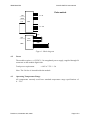
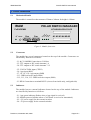
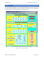
The module is a metal box that measures 250mm x 260mm. Its height is 120mm.
IRAM
POLAR SWITCH MANAGER
Reset
A7 A8 A9 A10 A11 A12
Can
Can
C1
C2
+5
VC
+3 AN
.3
V
+5 DC
VD
-5 C
VD
C
1p
ps
Full NOEMA
A1 A2 A3 A4 A5 A6
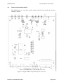
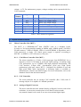
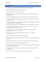
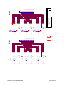
Figure 3: Module front view
5.2
Connectors
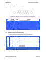
The module has several connectors located on the top of the module. Connectors are
classified by function as it follows:
- C1 & C2: SubDB9 Connection to CAN bus
- C3: TTL outputs to HV switch Antenna 1-6
- C4: TTL outputs to HV switch Antenna 7-12
- C5: 230VAC/50Hz input (CEE22)
- C6: 1pps input (BNC)
- C7, C8, C9, C10: 1pps output (SMB)
- C11: 5MHz reference input (SMA)
- C12, C13, C14, C15: 5MHz reference output (SMA)
- J3: HE10 Connection to terminal RS232 (Access from inside only, on digital-side)
5.3
Indicators
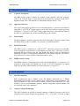
The module has tree external indicators located on the top of the module. Indicators
are classified by function as it follows:
- L1: 1pps green indicator (flashes when a 1pps signal is received)
- L2: Module powered (flashes when a CAN frame is received or transmitted)
- L2: +5V power supply for the external switches
- L4: -5V power supply for the external switches
Revision A, November 18th, 2009
Page 6 of 7