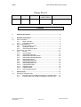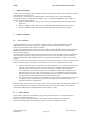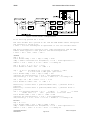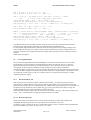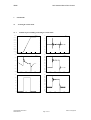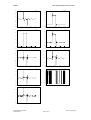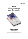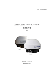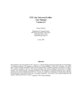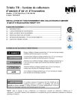
1
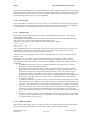
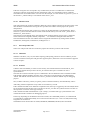
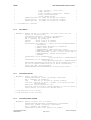
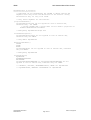
IRAM-PV02
Revision: 0
November 5, 2001
Contact Author
Institut de RadioAstronomie Millimétrique
Pico Veleta Antenna Mount
Drive Control
Owners
Alain Perrigouard ([email protected]),
Keywords:
Approved by:
A.Perrigouard
Date:
November 2003
Signature:
IRAM
NCS Antenna Mount Drive Control
Change Record
REVISION
DATE
AUTHOR
SECTION/PAGE
AFFECTED
REMARKS
Content
1
Hardware description.....................................................................................3
2
Software development...................................................................................3
2.1
Servo controllers........................................................................................3
2.1.1
Basic controller ..........................................................................3
2.1.2
Cascade controller.....................................................................4
Servo implementation................................................................................7
2.2.1
Kernel module int_ant................................................................7
2.2.2
Initialization tasks.......................................................................9
2.2.3
Slow and periodic tasks...........................................................10
Observation commands...........................................................................11
2.3.1
source ......................................................................................11
2.3.2
sourceOffsets...........................................................................12
2.3.3
setNextSubscanTrack .............................................................12
2.3.4
setNextSubscanSlewAzimuth..................................................12
2.3.5
setNextSubscanSlewElevation................................................13
2.3.6
setNextSubscanOtf..................................................................13
2.3.7
setNextSegmentLinear ............................................................13
2.3.8
setNextSegmentCircle .............................................................14
2.3.9
setNextSegmentCurve ............................................................14
2.3.10
prepareObservation .................................................................14
2.3.11
startObservation ......................................................................15
2.3.12
haltObservation........................................................................15
2.3.13
setPointingParameters ............................................................15
2.2
2.3
3
Some Results................................................................................................17
3.1
Tracking in cascade mode.......................................................................17
3.1.1
Azimuth step from 220deg to 220.2deg in cascade mode ......17
3.1.2
Elevation step from 45deg to 45.2deg in cascade mode ........18
Create Date:November 2001
NCSControl.doc
Author: A.Perrigouard
Page 2 of 19
IRAM
1
NCS Antenna Mount Drive Control
Hardware description
To drive the motor amplifiers and to read the encoders, a VME chassis replaces the old CAMAC interface
in the 30m New Control System.
Juan Penalver wrote already an extended document: 30M Antenna Control with VME Modules.
To summarize, there is a Single Board Computer in slot 1, a Motorola MVME2041 plus a number of
modules to interface the hardware:
• BC366, a VMEbus Time code processor, used for generating different interrupts and to feed a
NTP server.
• IK320, a VMEbus counter card, used to read the Heidenhain ROD800 main axes encoders.
• IK340, a VMEbus counter card, used to read the Heidenhain ROD456 motor encoders.
2
Software development
2.1
Servo controllers
The implementation of the servo controllers is based on the work of Rainer Bardenheuer and his
implementation made 18 years ago. Rainer’s controller software was executed on a CAMAC
microprocessor board and was written in assembler.
In the present implementation, the drives may be in different modes: PRESET, TRACK, INIT, STOP, etc.
PRESET and INIT assume that the axes are driven in velocity. That means that the servomechanisms
receive velocity requests.
TRACK and STOP mean that the positions of the axes are the controlled variables. The servomechanisms
may either receive velocity requests or torque requests. We call, servo controller, the part of this new
software implementation that implements the servo algorithm and establishes the velocity or the torque
requests.
Two bits per axis in the “output register for elevation, azimuth and subreflector control” are used to switch
from one mode of request to the other. In the following, the 2 cases are named basic and cascade.
•
•
In basic, when the position is controlled in a closed feedback, the servo controller implemented in
software is a PI controller. It is the case when the axis is in TRACK mode (variable request =
TRACK) and the servomechanism is in basic (variable track = BASIC). Remark that the
servomechanism is also in basic when the axis is in PRESET or INIT mode. In PRESET, The
algorithm checks in a slow (loose) loop the position error, i.e. the difference between the target
and the actual positions in order to reach the target at maximum speed/acceleration but without
overshoot which would be generated inevitably with only a PI filter.
In cascade, the servo loop always controls the drive position. The servo controller is a cascade of 2
PI controllers (position and velocity), the actual motor positions are feedback and there is a
mechanism of friction compensation.
In the following, the 2 controllers, basic and cascade, in their CAMAC and new VME implementations, are
presented. The names of the variables are the names either used in the source codes or in the manual
Antenna-ServoMechanism from R.Bardenheuer of November 20, 1985.
2.1.1
Basic controller
In the manual “Antenna-servomechanism” page 4-2 the proportional gain is 3 in azimuth and 2.5 in
elevation. The integration time is 5s.
However, the same coefficients are used in the CAMAC implementation (K=3) for both axes.
In the VME implementation we do the same choice, so, the same coefficients are used.
Create Date:November 2001
NCSControl.doc
Author: A.Perrigouard
Page 3 of 19
IRAM
NCS Antenna Mount Drive Control
Figure 1 - Basic Controller - Camac implementation
Ts is the loop period. Ts = 0.006s
Σ is the sum or the integration of the input.
KPMA = 3 * 2^15 / 36000
See KPMD in AZSERVO.LIS and ELSERVO.LIS
KIA = Ts / T = 0.006 / 5
See KID in AZSERVO.LIS and ELSERVO.LIS
Figure 2 - Basic Controller - VME implementation
Ts is the loop period. Ts = 2^-7s
Σ is the Sum or the integration of the input.
Kp = 3 * 2^15 / 100 / 2^12 = 0.24
let’s define kp = 0.24 * 2^10 = 246
Ki = Kp * Ts / T = 0.24 * 2^-7 / 5 = 0.000375
lets define ki such that 2^-ki ~= 0.000375 =>
2.1.2
ki = 11
Cascade controller
In the manual “Antenna-servomechanism” page 4-2 there is representation of the cascade controller with
the following definition of the variables:
phiCom reference axis position in rad.
phi actual axis position in rad.
phiComDot reference axis velocity in rad/s.
phiMotDot actual axis velocity in rad/s deduced from motor encoders and
corrected of the gear ratio.
To torque in mN applied to the antenna axis.
integral is the normal time integral of the input.
K = 2 s^-1 for Az and =2.5 s^-1 for El
T = 0.24s for Az and = 0.2s for El
KM = .9 10^9 mN s/rad for Az and = 1.5 10^9 mN s/rad for El
TM = 0.18s for Az and = 0.12s for El
Create Date:November 2001
NCSControl.doc
Author: A.Perrigouard
Page 4 of 19
IRAM
NCS Antenna Mount Drive Control
Figure 3 - Cascade controller - CAMAC implementation
Ts is the loop period. Ts = 0.006s
Σ is the Sum or the integration of the input.
Azimuth:
CASAK = K = 2
CASAT = Ts / T = 0.006 / 0.24s = 0.025
CASAKM = KM * RBGOFA
RBGOFA = PI/180/36000 * 2^15/265 * 1/14165
.1"s->rad
1/DAC gain gear-ratio
CASATM = Ts / TM = 0.006 / 0.18 = 0.03333
MVFCA = 6.35368867
Elevation:
CASEK = K = 2.5
CASET = Ts / T = 0.006 / 0.2s = 0.03
CASEKM = KM * RBGOFE
RBGOFE = PI/180/36000 * 2^15/265 * 1/15727
.1"s->rad
1/DAC gain gear-ratio
CASETM = Ts / TM = 0.006 / 0.12 = 0.05
MVFCE = 5.72264259
Create Date:November 2001
NCSControl.doc
Author: A.Perrigouard
Page 5 of 19
IRAM
NCS Antenna Mount Drive Control
Figure 4 - Cascade controller – VME implementation
Ts is the loop period. Ts = 2^-7s
The axis encoder has a period of 36" and the VME module IK320 interpoles
the period by a factor 2^12.
1 unit = 9 2^-10" and 1degree is equivalent to 100 2^12 encoder units.
The motor encoder has a period of 720" (1800 periods/rev) and the VME
module IK340 applies to the period a 256-fold interpolation.
1 unit = 360 * 3600 / 1800 / 256 "
Azimuth:
xkp = K = 2
let's define cXKp * 2^10 = xkp => cXKp = 2048
cXKp * xDelta overflows for abs(xDelta) > 2^31 / 2048 equivalent to
xdelta > 2^31 / 2048 * 9 2^-10 = 9216" ~= 2.56deg OK
xki = K * Ts / T = 2 * 2^-7 / 0.24
let's define 2^-cXKi = xki => cXKi = 4
vkp = .9 10^9 * PI/18000/2^12 * 2^15/265 * 1/14165 = .33477
KM
9 2^-10"->rad 1/DAC gain gear-ratio
let's define cVKp * 2^10 = vkp => cVKp = 343
overflow for abs(cVelocity) > 2^31 / 343 equivalent to
abs(cvelocity) > 2^31 / 343 * 9 2^-10 = 55027 "/s ~= 15.3deg/s OK
vki = vkp * Ts / TM = .33477 * 2^-7 / 0.18
let's define 2^-cVKi = vki => cVKi = 6
m1Velocity = actual motor 1 position(IK340 unit) - previous motor 1
position
m2Velocity = actual motor 2 position(IK340 unit) - previous motor 2
position
vkv = 1/2 360*3600/1800/256 * 2^7 *
1/14165
*
2^10/9
= 1.4458
IK340 unit -> "
1/Ts
gear-ratio "->9 2^10" unit
let's define cVKv * 2^10 = vkv => cVKv = 1480
Overflow for abs(CVelocity) > 2^31 / 2^10 equivalent to
abs(cvelocity) > 2^31 / 2^10 * 9 2^-10 = 18432"/s ~= 5.12deg/s OK
Elevation:
xkp = K = 2.5
let's define cXKp * 2^10 = xkp => cXKp = 2560
cXKp * xDelta overflows for abs(xDelta) > 2^31 / 2560 equivalent to
xdelta > 2^31 / 2560 * 9 2^-10 = 7373" ~= 2.05deg OK
Create Date:November 2001
NCSControl.doc
Author: A.Perrigouard
Page 6 of 19
IRAM
NCS Antenna Mount Drive Control
xki = K * Ts / T = 2.5 * 2^-7 / 0.2
let's define 2^-cXKi = xki => cXKi = 4
vkp = 1.5 10^9 * PI/18000/2^12 * 2^15/265 * 1/15727 = .50254
KM
9 2^-10"->rad 1/DAC gain gear-ratio
let's define cVKp * 2^10 = vkp => cVKp = 515
overflow for abs(cVelocity) > 2^31 / 515 equivalent to
abs(cvelocity) > 2^31 / 515 * 9 2^-10 = 36649 "/s ~= 10.2deg/s OK
vki = vkp * Ts / TM = .50254 * 2^-7 / 0.12
let's define 2^-cVKi = vki => cVKi = 5
dMot1 = actual motor 1 position(IK340 unit) - previous motor 1 position
vkv = 1/2 360*3600/1800/256 * 2^7 *
1/15727
*
2^10/9
= 1.3022
IK340 unit -> "
1/Ts
gear-ratio "->9 2^10" unit
let's define cVKv * 2^10 = vkv => cVKv = 1333
Overflow for abs(CVelocity) > 2^31 / 2^10 equivalent to
abs(cvelocity) > 2^31 / 1333 * 9 2^-10 = 14159"/s ~= 3.93deg/s OK
The implementation of the Cascade controller works perfectly in elevation with the above parameters
scaled from the values found in the Rainer’s documentation and in ELSERVO.LIS.
For the azimuth implementation the coefficients of the cascade position loop are slightly changed. The
scaled coefficients does not give a stable controller when an azimuth step position is applied. The new
proposed coefficients are a compromise between stability and low position error for tracking on a fixed
position:
cXKP=4096 and cXKi=6
2.2
Servo implementation
Linux powers the Single Board Computer MVME2041. Fast and real time operations are executed in
kernel modules. In those modules no floating number operations are allowed. The servo controller
algorithms performed in the fast loop of a kernel module are only coded with integer numbers. As a
consequence, all the operations should be verified carefully to avoid overflow or underflow.
The implementation is triggered by 2 periodic interrupts at 128Hz and 1Hz. The period of the fast interrupt
is ~7.8ms. It differs slightly from the 6ms period used in the Rainer’s implementation. This difference will
not change the overall response of the servo and the power of 2 selected for the frequency of 128Hz
simplifies greatly the coding.
2.2.1
Kernel module int_ant
This module provides 3 functions (itFast(), itSlow() and encoder()) to handle 2 periodic interrupts
generated by the bc366VME time code processor and the ik320 VME count card completion interrupts.
The 2 periodic interrupts are the so-called heartbeat at 128Hz and the 1pps generated every second. We use
the functions bc366_heartbeat_action() and bc366_pps_action() from the bc366 module to assign the
handlers and the functions itFast() and itSlow() to these interrupts.
The ik320 VME interrupts signals the end of the main axis encoder conversion. This interrupt, IRQ level 3,
vector = 0xC1, is handled by this module by calling the function encoder().
2.2.1.1
Heartbeat interrupt
The function itFast() starts the main axes encoder position latching procedure and requests to the
ik320VME module the generation of an interruption for the end of the conversion.
It reads the 2 motor encoders for the axes, azimuth and elevation. Then, it calculates the motor differential
positions and deduces the motor velocities in 9 2^-10”/s units.
Create Date:November 2001
NCSControl.doc
Author: A.Perrigouard
Page 7 of 19
IRAM
NCS Antenna Mount Drive Control
The function has a conditional section compiled when the variable NOIK320 is defined: In a development
situation when there is neither main axis encoder nor VME module ik320, the variables az.x0 and el.x0 are
extrapolated here and the function move() is also called here(instead of being called after the reception of
the ik320 interrupt driven by the conversion completion).
2.2.1.2
1pps interrupt
The function itSlow() calculates for each axis, x0 and x1. x0 is the reference position for this current 1pps
interrupt time and x1 is the reference position for the next 1pps interrupt time. dx is equal to the difference
x1-x0 and sumDx is cleared. SumDx is used to accumulate dx every 7.8ms in encoder().
2.2.1.3
ik320 interrupt
The function encoder() reads the ik320 status register and depending on which axis is ready, reads the
corresponding latched counters.
If the condition variable SIMULATION is no defined, the variable xActual is calculated from the actual
values of the latch counters and is saved in the shared memory area.
If the drive is in remote, the variable xReference and vReference are updated:
sumDx += dx
xReference = x0 + dx
vReference = dx
If the variable MOVE_TEST is not defined (it’s the normal situation) the function move() is called. The
variable MOVE_TEST has been defined once to allow the execution of the task moveTest and the
debugging of the function move() which is called by moveTest.
The function move() implements the servo code. It is called for each axis, as soon as the actual encoder
position is read.
The position error, px->xDelta, is calculated and depending on the variable px->request, different
algorithms may be applied. px->xDelta is the difference between px->xReference and px->xActual.
The variable px->request may have the possible values: R_PRESET, R_TRACK, R_SLEW, R_STOP or
R_TRSFER.
• R_TRSFER is foreseen for a session of collecting data and for calculating the drive transfer
function. It is not tested with the 30m antenna.
• R_PRESET is used to request the drive to reach a given position after a constant acceleration
phase, a phase of displacement at maximum speed and then a constant deceleration phase. For a
short distance, the phase at constant and maximum speed may not exist. This mode is always
requested for a medium or long distance displacement to avoid tracking algorithm overshoot.
When the absolute value of the axis velocity is under a certain threshold (px->xVelocityEpsil) and
the absolute value of the position error is lower than px->xDeltaMin, the axis request mode is
switched to R_TRACK.
• R_TRACK is used to track a position. The servo mechanism is either in basic mode or in cascade
mode depending on the variable px->track equal to BASIC or CASCADE. Note that whatever the
value of px->track the BASIC servo mechanism is used when the axis px->request is R_PRESET.
• R_STOP is used to keep the axis on a fixed position. When the axis px->request is set to R_STOP
while it is moving, the axis is slow down and then is requested to track to the reached position by
switching px->request to TRACK. Note that the DAC output will increase up to its maximum
value if this mode is requested and the axis is locked for any reason (brake, amplifier switched off,
etc…)
• R_SLEW is used to move the axis in basic mode and at constant speed. The axes are in this mode
at start time with a requested velocity px->vReference set to 0. This mode keeps the DAC output
to 0 until the antenna is free to move.
2.2.1.4
Module installation
Before installing this module, universe.o and bc336.o have to be installed and the encoder VME modules
should be initialized. The installation procedure starts with the 2 kernel module installation:
Create Date:November 2001
NCSControl.doc
Author: A.Perrigouard
Page 8 of 19
IRAM
NCS Antenna Mount Drive Control
modprobe universe
modprobe bc336
We consider that the main axis encoder VME module ik320 has been already initialised and it is running.
Another initialization of the VME module would cause a re-initialization of the incremental encoders.
As a consequence, ik320Init is commented out in the procedure.
The motor encoder VME module ik340 is initialized by calling ik340Init:
#/control/antenna/bin/ik320Init
/control/antenna/bin/ik340Init
And finally:
insmod /control/antenna/bin/int_ant
2.2.2
Initialization tasks
The encoder VME module initialization tasks have to be executed before installing int_ant.o.
If ik320Init is executed, the incremental encoders should be re-initialized and the axes should be turned
enough to pass their init points and to reset the counters.
ik340Init initializes the motor encoder VME module and can be executed at re-installation time.
2.2.2.1
ik320Init
The task ik320Init is based on a source code written by Juan Penalver: ik320.c.
The IK320 VMEbus Counter Card user’s manual and in particular the program example are necessary to
understand this program executed to initialize the VME module.
2.2.2.2
Ik340Init
The task ik340Init is based on a source code written by Juan Penalver: readenc.c.
The IK340 VMEbus Counter Card user’s manual is necessary to understand this program executed to
initialize the VME module.
2.2.2.3
initAntenna
Once the kernel module int_ant.o is installed and the shared memory area described with the structure
struct s_antenna is registered, the task initAntenna can initialize the elements of the shared memory area.
The function antdata() returns the address of this area in the user space domain by calling mmap() . The
function mmap() is one of the functions implemented in int_ant.o which is available for the device
/dev/int_ant and in particular for its descriptor.
The struct s_antenna describes the content of this shared memory area. The struct s_antenna is declared in
s_antenna.h.
This task sets the servo variables to their default values and switches the servo mechanisms, azimuth and
elevation, to basic mode.
2.2.2.4
Config
The task config is called just after initAntenna in the installation procedure but can be called at anytime
later in order to modify some configuration variables.
The values of the configuration variables are found in the file /control/antenna/config.30m. The format of
each line of this file is:
Variable_name value
For instance:
az.kp 246 Az proportional factor
Create Date:November 2001
NCSControl.doc
Author: A.Perrigouard
Page 9 of 19
IRAM
NCS Antenna Mount Drive Control
If the first string does not correspond to any variable name, the line is considered as a comment line.
All strings, following on the same line the configuration value, are considered as well as comments.
The notation for the variable names is obvious. For the example, az is the element of type struct s_axes of
the structure s_antenna and kp is one element of this struct s_axes.
2.2.2.5
InitObservation
This task initializes the structures needed to define the sources and the subscans for the observations. This
task should be executed before starting the slow periodic task evItSlow which prepares the position
interpolations.
The task calls the function shm_connect() to connect to the shared memory area identified by ‘PICO’.
The struct s_observation describes the content of this shared memory area. The struct s_observation is
declared in s_observation.h.
The task sets to some default values, the elements of the structure slaInput of type struct s_slaParams.
Those elements like longitude, latitude, temperature … are needed for calling the slalib functions.
The task initializes also the roots and the chains of segments and subscans by setting all the variables
firstSubscan, firstSegment, nextSubscan, nextSegment to –1.
2.2.3
Slow and periodic tasks
These slow and periodic tasks are executed to prepare the reference positions and velocities.
2.2.3.1
SlaParams
slaParams calculates, every 10s, the tables amprms[] and aoprms[] which are used in evItSlow() for the
conversions between mean place and geocentric apparent place, and for the conversions between apparent
to observed place.
2.2.3.2
EvItSlow
evItSlow calls first antdata() to connect to the memory area shared with the kernel module int_ant.o.
Next it opens the file descriptor fd to /dev/int_ant. This file descriptor is used later for the 1s
synchronization.
Note that this connection and this open are conditioned to the non-definition of the variable PCTCP00.
If PCTCP00 is defined, antdata() executes only a connection to a shared memory area identified by
‘ANTE’ and defined with the same structure struct s_antenna. PCTP00 is defined only for debugging
purpose.
Next, evItSlow calls shm_connect() to get the pointer of the shared memory area identified by ‘PICO’.
And finally, eItSlow implements a loop which is executed every second.
If the variable PCTCP00 is not defined at compilation time, the loop is triggered by the call read(fd) which
has for argument fd, the file descriptor to the device /dev/int_ant. This call synchronizes the execution of
the loop to the occurrence of the 1pps interrupts.
If the variable PCTCP00 is defined there is just a sleep(1) to simulate this 1pps synchronization. The
variable PCTCP00 is used here for debugging purpose.
In the loop, depending on the different observation modes, the commanded positions, az.command and
el.command are calculated and finally are converted in encoder units (9 2^-10 arc-seconds) before being
assigned to az.x2 and el.x2.
The different observation modes are: IDLE, HORIZON, PREPARE, READY, RUN and STOP.
Create Date:November 2001
NCSControl.doc
Author: A.Perrigouard
Page 10 of 19
IRAM
NCS Antenna Mount Drive Control
For the mode PREPARE, the function prepareScan() is called. If the time to prepare is passed, the scan
starting position is evaluated and when this starting position is reached, the observation mode is switched to
READY.
For the mode READY, the function readyScan() is called. If a time to stop is defined and this time is
passed, the observation mode is switched to STOP. Otherwise, if the time to start is passed, the observation
mode is switched to RUN.
For the mode RUN, the function runScan() is called. The function calculates the running positions
depending on the type of the current subscan. If a time to stop is defined and this time is passed, the
observation mode is switched to STOP. If there is no more subscan or they have not yet been defined, the
observation mode is switched to READY.
For the mode STOP, the function stopScan() is called. The function requests the axes to stop immediately
and it clears the integration buffers of the cascade servos.
2.3
Observation commands
These observation commands correspond to the signatures (number of arguments, type, meaning) listed in
the document antennaMountDrive.h. This document edited by W.Brunswig, A.Sievers, H.Ungerechts and
A.Perrigouard defines the interface between the coordination and synchronization tasks and the mount
drive observation tasks and modules:
2.3.1
source
* ABSTRACT : Define a new source.
*
*
source <sourName> <basisSystem> <equinoxSystem> <equinoxYear> \*
* <lambda> <beta> <descriptiveSystem> <alphaD> <betaD> <gammaD> \
*
* <projection> <lambdaProjection> <betaProjection> < kappaProjection>
*
*
All arguments are mandatory.
*
*
sourceName
name of the source or NULL
*
*
basisSystem
one number [0,6] among the basisSystemEnum
*
*
0 GALATIC, galactic
*
*
1 EQUATORIAL,mean equatorial
*
*
2 APPARENTEQUATORIAL, apparent equatorial
*
*
3 ECLIPTIC, mean ecliptic
*
*
4 APPARENTECLIPTIC, apparent ecliptic
*
*
5 HADEC, apparent hour angle and declination
*
*
6 HORIZONTAL
*
*
equinoxSystem
one number [0,1] among the equinoxSystemEnum
*
*
0 J, IAU 1976, FK5, Fricke system
*
*
1 B, Bessel-Newcomb, FK4 system
*
*
equinoxYear
year of the equinox
*
*
lambda
source longitude (radian)
*
*
beta
source latitude (radian)
*
*
descriptiveSystem one number among the descriptiveSystemEnum
*
*
0 NODESCRIPTIVE, no descriptive system
*
*
1 ORIGIN, origin definition of descriptive sys.*
*
2 POLAR, polar definition of descriptive system*
*
3 EULER,Euler definition of descriptive system *
*
alphaD
1st angle for descriptive system (radian)
*
*
betaD
2nd angle for descriptive system (radian)
*
*
gammaD
3rd angle for descriptive system (radian)
*
*
projection
one number among the projectionEnum choice
*
*
0 NOPROJECTION, no projection
*
*
1 RADIO, "radio" convention with 1/cos(beta)
*
*
2 TAN, gnomonic
*
*
3 SIN, orthographic
*
*
4 STG, stereographic
*
*
5 ARC, zenithal equidistant
*
*
6 ZEA, zenithal equal area
*
Create Date:November 2001
NCSControl.doc
Author: A.Perrigouard
Page 11 of 19
IRAM
*
*
*
*
*
*
*
*
NCS Antenna Mount Drive Control
7 CAR, cartesian / plate caree
8 MER, mercator
9 CEA, cylindrical equal area / Lambert
10 GLS, Sanson-Flansteed
11 AIT, Hammer-Aitoff
lambdaProjection 1st angle for projection (radian)
betaProjection
2nd angle for projection (radian)
kappaProjection 3rd angle for projection (radian)
*
*
*
*
*
*
*
*
!!! sourceName not archived
2.3.2
sourceOffsets
* ABSTRACT : Define offsets to be applied to the next source (not the
*
current or active source).
*
sourceOffset <xOffset> <yOffset> <systemOffset>
*
The next source has to be already defined.
*
The 3 arguments are mandatory.
*
xOffset
offset along x in radians
*
yOffset
offset along y in radians
*
systemOffset one number [0,7] among the enum systemOffsetEnum
*
0 PROJECTION
*
1 DESCRIPTIVE, descriptive coordinates
*
2 BASIS, basis system
*
3 EQUATORIALOFF, mean equatorial J2000.0
*
4 HADECOFF, (apparent) hour angle and declination
*
5 HORIZONTALTRUE, az with 1/cos(el) factor and el
*
6 HORIZONTALOFF, azimuth and elevation
*
7 NASMYTH
*
systemOffset can be PROJECTION if
*
source.projection != NOPROJECTION
*
systemOffset can be DESCRIPTIVE if
*
source.descriptiveSystem != NODESCRIPTIVE
*
PROJECTION, DESCRIPTIVE and BASIS are mutually execlusive and
*
the last accepted command with one of these systemOffsets
*
clears the other related offsets.
*
HORIZONTALTRUE and HORIZONTALOFF are mutually exclusive.
2.3.3
*
*
*
*
*
*
*
*
*
*
*
*
*
*
*
*
*
*
*
*
*
*
*
*
setNextSubscanTrack
* ABSTRACT : Define a subscan track
*
setNextSubscanTrack <time> <traceFlag> <subscanId>
*
The 3 arguments are mandatory.
*
time
duration of tracking in seconds (double)
*
traceFlag add flag to trace, a number [0,18] among the enum
*
traceFlagsEnum
*
subscanId subscan identifier (int)
*
A passive source should be already defined. In case no passive
*
source exists, an active source should exists.
*
*
*
*
*
*
*
*
*
!!! The duration is not a string
!!! The subscanId is not a string
2.3.4
setNextSubscanSlewAzimuth
* ABSTRACT : Define a subscan slew in azimuth.
*
setNextSubscanSlewAzimuth <azimuthStart> <azimuthEnd>
*
<elevation> <speed> <traceFlag> <subscanId>
*
The 6 arguments are mandatory.
*
azimuthStart azimuth start position in radians
Create Date:November 2001
NCSControl.doc
Author: A.Perrigouard
Page 12 of 19
*
*
*
*
*
IRAM
*
*
*
*
*
*
*
*
NCS Antenna Mount Drive Control
azimuthEnd
elevation
speed
traceFlag
azimuth end position in radians
elevation in radians
speed in radians/second
add flag to trace, a number [0,18] among the enum
traceFlagsEnum
subscanId
subscan identifier (int)
A passive source should be already defined. In case no passive
source exists, an active source should exists.
*
*
*
*
*
*
*
*
!!! The subscanId is not a string
2.3.5
setNextSubscanSlewElevation
* ABSTRACT : Define a subscan slew in elevation.
*
setNextSubscanSlewElevation <elevationStart> <elevationEnd>
*
<azimuth> <speed> <traceFlag> <subscanId>
*
The 6 arguments are mandatory.
*
elevationStart azimuth start position in radians
*
elevationEnd
azimuth end position in radians
*
azimuth
elevation in radians
*
speed
speed in radians/second
*
traceFlag
add flag to trace, a number [0,18] among the
*
enum traceFlagsEnum
*
subscanId
subscan identifier (int)
*
A passive source should be already defined. In case no passive
*
source exists, an active source should exists.
*
*
*
*
*
*
*
*
*
*
*
*
*
!!! The subscanId is not a string
2.3.6
setNextSubscanOtf
* ABSTRACT : Define a subscan On The Fly.
*
setNextSubscanOtf <systemOffset> <subscanId>
*
The 2 arguments are mandatory.
*
systemOffset one number [0,7] among the enum systemOffsetEnum
*
0 PROJECTION
*
1 DESCRIPTIVE, descriptive coordinates
*
2 BASIS, basis system
*
3 EQUATORIALOFF, mean equatorial J2000.0
*
4 HADECOFF, (apparent) hour angle and declination
*
5 HORIZONTALTRUE, az with 1/cos(el) factor and el
*
6 HORIZONTALOFF, azimuth and elevation
*
7 NASMYTH
*
subscanId
subscan identifier (int)
*
A passive source should be already defined. In case no passive
*
source exists, an active source should exists.
*
If systemOffset is equal to PROJECTION or DESCRIPTIVE, the
*
descriptiveSystem or projection have to be already defined in
*
the source.
*
*
*
*
*
*
*
*
*
*
*
*
*
*
*
*
*
*
!!! The subscanId is not a string
2.3.7
setNextSegmentLinear
* ABSTRACT : Define a linear otf segment.
*
setNextSegmentLinear <xStart> <yStart> <xEnd> <yEend>
*
<speedStart> <speedEnd> <traceFlag> <subscanId>
*
xStart
start in x (radian)
*
yStart
start in y (radian)
*
xEnd
end in x (radian)
Create Date:November 2001
NCSControl.doc
Author: A.Perrigouard
Page 13 of 19
*
*
*
*
*
*
IRAM
*
*
*
*
*
*
*
NCS Antenna Mount Drive Control
yEnd
end in y (radian)
*
speedStart
start with this speed (radian/second)
*
speedEnd
end with this speed (radian/second)
*
traceFlag
add flag to trace
*
subscanId
subscan identifier (int)
*
Adds a segment to an otf subscan identified by subscanId as far*
this subscan has been defined and still exits
*
!!! The subscanId is not a string
!!! traceFlag not implemented
2.3.8
setNextSegmentCircle
* ABSTRACT : Define a circular otf segment.
*
*
setNextSegmentLinear <xStart> <yStart> <xEnd> <yEend>
*
*
<turnAngle> <speedStart> <speedEnd> <traceFlag> <subscanId>
*
*
xStart
start in x (radian)
*
*
yStart
start in y (radian)
*
*
xEnd
end in x (radian)
*
*
yEnd
end in y (radian)
*
*
turnAngle
turn angle (radian)
*
*
speedStart
start with this speed (radian/second)
*
*
speedEnd
end with this speed (radian/second)
*
*
traceFlag
add flag to trace
*
*
subscanId
subscan identifier (int)
*
*
Adds a segment to an otf subscan identified by subscanId as far*
*
this subscan has been defined and still exits
*
!!! The subscanId is not a string
!!! traceFlag not implemented
2.3.9
setNextSegmentCurve
* ABSTRACT : Define a Bezier curve otf segment.
*
*
setNextSegmentLinear <xStart> <yStart> <xEnd> <yEend>
*
*
<turnAngle> <speedStart> <speedEnd> <traceFlag> <subscanId>
*
*
xStart
start in x (radian)
*
*
yStart
start in y (radian)
*
*
xEnd
end in x (radian)
*
*
yEnd
end in y (radian)
*
*
xCpStart
x of control point at start (radian)
*
*
yCpStart
y of control point at start (radian)
*
*
xCpEnd
x of control point at end (radian)
*
*
yCpEnd
y of control point at end (radian)
*
*
speedStart
start with this speed (radian/second)
*
*
speedEnd
end with this speed (radian/second)
*
*
traceFlag
add flag to trace
*
*
subscanId
subscan identifier (int)
*
*
Adds a segment to an otf subscan identified by subscanId as far*
*
this subscan has been defined and still exits
*
!!! The subscanId is not a string
!!! traceFlag not implemented
2.3.10
prepareObservation
* ABSTRACT : Request to prepare the next scan (next source).
*
Syntax:
*
prepareObservation <when>
*
The argument is mandatory.
Create Date:November 2001
NCSControl.doc
*
*
*
*
Author: A.Perrigouard
Page 14 of 19
IRAM
*
*
*
*
*
*
*
2.3.11
NCS Antenna Mount Drive Control
when
ISO 8601 date
The command cleans all subscans and segments still connected
to the active scan before switching to the next source.
The command "prepare" has a sense if the next source (passive)
has already been defined. If the next source is not yet
defined, the observation mode is set to STOP.
The command resets the observation start time and stop time
*
*
*
*
*
*
*
startObservation
* ABSTRACT : Request to start a scan.
*
*
Syntax
*
*
startObservation <when>
*
*
The argument is mandatory.
*
*
when
ISO 8601 date
*
*
When the observation mode becomes READY and the specified date *
*
<when> is past, then the observation starts to proceed through *
*
the subscans. The mode is set to RUN. If there is no subscan
*
*
the startObservation time slot is forgotten and the observation*
*
start time is reset.
*
2.3.12
haltObservation
* ABSTRACT : Request to stop a scan.
*
*
Syntax
*
*
startObservation <when>
*
*
The argument is mandatory.
*
*
when
ISO 8601 date
*
*
The command stops an observation (or scan) but don't clean the *
*
subscans still pending.
*
2.3.13
setPointingParameters
* ABSTRACT : Define the pointing parameters
*
setPointingParameters p1, p2, p3, p4, p5, p7, p8, p9, rxh0,
*
rxve
*
p1
Azimuth encoder zero point error
*
p2
Collimation error in azimuth
*
p3
Collimation error of axes
*
p4
Inclination 1
*
p5
Inclination 2
*
p7
Elevation encoder zero point error
*
p8
Bending term 1
*
p9
Bending term 2 (Bernd Harald)
*
rxho
Horizontal receiver offset in Nasmyth
*
rxve
Vertical receiver offset in Nasmyth
*
The 10 arguments are mandatory.
Useful test commands:
=====================
config
dmpAntenna
dmpObservation
initAntenna
initObservation
horizon
record
scope
stopDrive
Create Date:November 2001
NCSControl.doc
Author: A.Perrigouard
Page 15 of 19
*
*
*
*
*
*
*
*
*
*
*
*
*
*
IRAM
NCS Antenna Mount Drive Control
Implementation in evItSlow:
===========================
!!!SubscanId are not implemented. Not needed to define subscan OTF
segments since they follow the declaration of the subscan. String
subscanId are very too long to be saved.
!!!Only linear segments for OTF subscans.
projectionToNative()
sourceOffsetProjection are not applied in case of subscan OTF,
otherwise they
are added.
p_source->lambda and p_source->beta are not used if projection is
neither NOPROJECTION nor RADIO.
!!!Everything implemented except AIT.
nativeToDescriptive()
sourceOffsetDescriptive are not applied in case of subscan OTF,
otherwise they are added.
!!!Only RADIO implemented
descriptiveToBasis()
ORIGIN
POLAR
EULER
sourceOffsetBasis are not applied in case of subscan OTF, otherwise
they are added.
!!!Everything implemented:
basisToHorizon()
EQUATORIAL
APPARENTEQUATORIAL
HORIZONTAL
sourceOffsetHORIZONTALTRUE or sourceOffsetsHORIZONTALOFF are not
applied in case of subscan OTF, otherwise they are added.
!!! GALACTIC, ECLIPTIC, APPARENTECLIPTIC, HADEC not implemented
!!! EQUATORIALOFF, HADECOFF and NASMYTH not implemented
Create Date:November 2001
NCSControl.doc
Author: A.Perrigouard
Page 16 of 19
IRAM
3
NCS Antenna Mount Drive Control
Some Results
3.1
Tracking in cascade mode
3.1.1
Azimuth step from 220deg to 220.2deg in cascade mode
9.02e+07
1500
xReference
xDelta
9.019e+07
1000
9.018e+07
9.017e+07
500
9.016e+07
0
9.015e+07
9.014e+07
-500
9.013e+07
-1000
9.012e+07
9.011e+07
640000
645000
650000
655000
660000
665000
30000
-1500
640000
645000
650000
655000
660000
665000
16000
cXIntegral
cVIntermediate
14000
20000
12000
10000
10000
8000
6000
0
4000
2000
-10000
0
-2000
-20000
-4000
-30000
640000
645000
650000
655000
660000
665000
12000
-6000
640000
645000
650000
655000
660000
665000
16000
vReference
mVelocity
14000
10000
12000
10000
8000
8000
6000
6000
4000
2000
4000
0
-2000
2000
-4000
0
640000
645000
650000
Create Date:November 2001
NCSControl.doc
655000
660000
665000
-6000
640000
645000
650000
655000
660000
665000
Author: A.Perrigouard
Page 17 of 19
IRAM
NCS Antenna Mount Drive Control
15000
150000
cVelocity
cVIntegral
10000
100000
5000
50000
0
0
-5000
-50000
-10000
-100000
-15000
640000
645000
650000
655000
660000
665000
4000
-150000
640000
645000
650000
655000
665000
800
torque
friction
3000
600
2000
400
1000
200
0
0
-1000
-200
-2000
-400
-3000
-600
-4000
640000
660000
645000
650000
655000
660000
665000
-800
640000
645000
650000
655000
660000
665000
4000
dac
3000
2000
1000
0
-1000
-2000
-3000
-4000
640000
3.1.2
645000
650000
655000
660000
665000
Elevation step from 45deg to 45.2deg in cascade mode
1.852e+07
1500
xReference
xDelta
1.851e+07
1000
1.85e+07
1.849e+07
500
1.848e+07
0
1.847e+07
1.846e+07
-500
1.845e+07
-1000
1.844e+07
1.843e+07
1.03e+06
1.035e+06
1.04e+06
Create Date:November 2001
NCSControl.doc
1.045e+06
1.05e+06
1.055e+06
-1500
1.03e+06
1.035e+06
1.04e+06
1.045e+06
1.05e+06
1.055e+06
Author: A.Perrigouard
Page 18 of 19
IRAM
NCS Antenna Mount Drive Control
40000
30000
cXIntegral
cVIntermediate
30000
25000
20000
20000
10000
15000
0
10000
-10000
5000
-20000
0
-30000
-40000
1.03e+06
1.035e+06
1.04e+06
1.045e+06
1.05e+06
1.055e+06
25000
-5000
1.03e+06
1.035e+06
1.04e+06
1.045e+06
1.05e+06
1.055e+06
30000
vReference
mVelocity
25000
20000
20000
15000
15000
10000
10000
5000
0
5000
-5000
0
1.03e+06
1.035e+06
1.04e+06
1.045e+06
1.05e+06
1.055e+06
25000
-10000
1.03e+06
1.035e+06
1.04e+06
1.045e+06
1.05e+06
1.055e+06
200000
cVelocity
cVIntegral
20000
150000
15000
10000
100000
5000
0
50000
-5000
0
-10000
-15000
-50000
-20000
-25000
1.03e+06
1.035e+06
1.04e+06
1.045e+06
1.05e+06
1.055e+06
15000
-100000
1.03e+06
1.035e+06
1.04e+06
1.045e+06
1.05e+06
1.055e+06
800
torque
friction
600
10000
400
200
5000
0
0
-200
-400
-5000
-600
-10000
1.03e+06
1.035e+06
1.04e+06
1.045e+06
1.05e+06
1.055e+06
-800
1.03e+06
1.035e+06
1.04e+06
1.045e+06
1.05e+06
1.055e+06
15000
dac
10000
5000
0
-5000
-10000
1.03e+06
1.035e+06
1.04e+06
Create Date:November 2001
NCSControl.doc
1.045e+06
1.05e+06
1.055e+06
Author: A.Perrigouard
Page 19 of 19