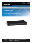
1
March TL704A 2009 codescodes TL708A codescodes codescodes RS-232 Modem Sharing Device Expand existing, leased line, polled networks BLACK BOX without adding computer ports or communications links. ® Four- and eight-port models available. Customer Support Information Order toll-free in the U.S.: Call 877-877-BBOX (outside U.S. call 724-746-5500) FREE technical support 24 hours a day, 7 days a week: Call 724-746-5500 or fax 724-746-0746 • Mailing address: Black Box Corporation, 1000 Park Drive, Lawrence, PA 15055-1018 • Web site: www.blackbox.com • E-mail: [email protected] Trademarks Used in this Manual/Safety Warning/Disclaimer Trademarks Used in this Manual Black Box and the Double Diamond logo are registered trademarks of BB Technologies, Inc. UL is a registered trademark of Underwriters’ Laboratories. Any other trademarks mentioned in this manual are acknowledged to be the property of the trademark owners. SAFETY WARNING Always observe standard safety precautions during installation, operation, and maintenance of this product. To avoid the possibility of electrical shock, be sure to disconnect the power cord from the power source before you remove the IEC power fuses or perform any repairs. DISCLAIMER Black Box Network Services shall not be liable for damages of any kind, including, but not limited to, punitive, consequential or cost of cover damages, resulting from any errors in the product information or specifications set forth in this document and Black Box Network Services may revise this document at any time without notice. Page 2 724-746-5500 | blackbox.com FCC and IC RFI Statements/NOM Statement FEDERAL COMMUNICATIONS COMMISSION AND INDUSTRY CANADA RADIO FREQUENCY INTERFERENCE STATEMENTS This equipment generates, uses, and can radiate radio-frequency energy, and if not installed and used properly, that is, in strict accordance with the manufacturer’s instructions, may cause interference to radio communication. It has been tested and found to comply with the limits for a Class A computing device in accordance with the specifications in Subpart B of Part 15 of FCC rules, which are designed to provide reasonable protection against such interference when the equipment is operated in a commercial environment. Operation of this equipment in a residential area is likely to cause interference, in which case the user at his own expense will be required to take whatever measures may be necessary to correct the interference. Changes or modifications not expressly approved by the party responsible for compliance could void the user’s authority to operate the equipment. This digital apparatus does not exceed the Class A limits for radio noise emission from digital apparatus set out in the Radio Interference Regulation of Industry Canada. Le présent appareil numérique n’émet pas de bruits radioélectriques dépassant les limites applicables aux appareils numériques de la classe A prescrites dans le Règlement sur le brouillage radioélectrique publié par Industrie Canada. Normas Oficiales Mexicanas (NOM) Electrical Safety Statement INSTRUCCIONES DE SEGURIDAD 1. Todas las instrucciones de seguridad y operación deberán ser leídas antes de que el aparato eléctrico sea operado. 2. Las instrucciones de seguridad y operación deberán ser guardadas para referencia futura. 3. Todas las advertencias en el aparato eléctrico y en sus instrucciones de operación deben ser respetadas. 4.Todas las instrucciones de operación y uso deben ser seguidas. 724-746-5500 | blackbox.com Page 3 NOM Statement 5. El aparato eléctrico no deberá ser usado cerca del agua — por ejemplo, cerca de la tina de baño, lavabo, sótano mojado o cerca de una alberca, etc. 6. El aparato eléctrico debe ser usado únicamente con carritos o pedestales que sean recomendados por el fabricante. 7. El aparato eléctrico debe ser montado a la pared o al techo sólo como sea recomendado por el fabricante. 8. Servicio — El usuario no debe intentar dar servicio al equipo eléctrico más allá lo descrito en las instrucciones de operación. Todo otro servicio deberá ser referido a personal de servicio calificado. 9. El aparato eléctrico debe ser situado de tal manera que su posición no interfiera su uso. La colocación del aparato eléctrico sobre una cama, sofá, alfombra o superficie similar puede bloquea la ventilación, no se debe colocar en libreros o gabinetes que impidan el flujo de aire por los orificios de ventilación. 10. El equipo eléctrico deber ser situado fuera del alcance de fuentes de calor como radiadores, registros de calor, estufas u otros aparatos (incluyendo amplificadores) que producen calor. 11. El aparato eléctrico deberá ser connectado a una fuente de poder sólo del tipo descrito en el instructivo de operación, o como se indique en el aparato. 12. Precaución debe ser tomada de tal manera que la tierra fisica y la polarización del equipo no sea eliminada. 13. Los cables de la fuente de poder deben ser guiados de tal manera que no sean pisados ni pellizcados por objetos colocados sobre o contra ellos, poniendo particular atención a los contactos y receptáculos donde salen del aparato. 14. El equipo eléctrico debe ser limpiado únicamente de acuerdo a las recomendaciones del fabricante. 15. En caso de existir, una antena externa deberá ser localizada lejos de las lineas de energia. 16. El cable de corriente deberá ser desconectado del cuando el equipo no sea usado por un largo periodo de tiempo. Page 4 724-746-5500 | blackbox.com NOM Statement 17. Cuidado debe ser tomado de tal manera que objectos liquidos no sean derramados sobre la cubierta u orificios de ventilación. 18. Servicio por personal calificado deberá ser provisto cuando: A: El cable de poder o el contacto ha sido dañado; u B: Objectos han caído o líquido ha sido derramado dentro del aparato; o C: El aparato ha sido expuesto a la lluvia; o D: El aparato parece no operar normalmente o muestra un cambio en su desempeño; o E: El aparato ha sido tirado o su cubierta ha sido dañada. 724-746-5500 | blackbox.com Page 5 Table of Contents Table of Contents 1.Specifications....................................................................................... 7 2. Overview ....................................................................................... 8 2.1 Introduction.................................................................................. 8 2.2 Theory of Operation..................................................................... 9 2.3 What’s Included............................................................................ 9 2.4 Hardware Description................................................................. 10 3. Basic Operation..................................................................................... 11 3.1 Front Panel Indicators and Switches............................................ 11 3.2 Rear Panel Connectors and Fuses............................................... 11 3.3 Clocking..................................................................................... 11 3.4 Electrical Interface....................................................................... 11 3.5 Subchannel Service Modes......................................................... 11 3.5.1 Subchannel Scanning Mode......................................... 11 3.5.2 Subchannel Priority Mode............................................. 12 3.5.3 Subchannel RTS to CTS Delay....................................... 12 3.6 Anti-Streaming............................................................................ 12 3.6.1 Automatic DTE Removal............................................... 12 3.6.2 Manual DTE Removal.................................................... 12 3.6.3 Unexplained Streaming Terminals................................. 13 3.7 Dial Modem Support.................................................................. 13 3.8 Cascading or Concatenation....................................................... 13 4. Installation ..................................................................................... 15 4.1 Voltage Selection........................................................................ 15 4.2 Voltage Selection Fuses.............................................................. 15 4.3 Power Connection...................................................................... 15 4.4 Default Configuration Switch Settings........................................ 16 4.5 Modem (DCE) and Terminal (DTE) Connection........................... 16 4.6 Internal Switch Settings............................................................... 16 4.6.1 DIP Switches................................................................. 16 4.6.2 DTR Jumper Option...................................................... 17 4.6.3 “OR” Mode Jumper Options........................................ 17 4.6.4 Anti-Streaming (SW1-4)................................................ 17 4.6.5 Channel Service Modes (SW-5).................................... 17 4.6.6 Frame to Signal Ground (SW-6).................................... 18 4.6.7 “OR” Mode and Other Options................................... 18 Appendix. EIA Interface Chart....................................................................... 19 Page 6 724-746-5500 | blackbox.com Chapter 1: Specifications 1. Specifications Anti-Streaming Automatic: Selectable timeout intervals; Disable: Selectable via DIP switch Application Works with up to (4) sync/async terminal or DTE devices operating in a polled environment to share one modem. Approvals Safety: UL® 1950, CSA C22.2 Capacity (4) or (8) RS-232 sync/async devices Data Format Data transparent at all data rates Data Rate Up to 120 kbps Flow Control Handshaking: RTS/CTS, Optional “OR” mode Terminal Service Modes Rotational sequence for equal access Timing External, from the attached modem User Controls For each subchannel: (1) Enable/disable switch Interface EIA RS-232, CCITT V.24 using DB25 female connectors Connectors TL704A: (4) DB25 F, (1) DB25 F master port; TL708A: (8) DB25 F, (1) DB25 F master port Indicators TL704A: (11) LEDs: (1) Power, (1) SD, (1) RD, (4) Active, (4) Stream; TL708A: (19) LEDs: (1) Power, (1) SD, (1) RD, (8) Active, (8) Stream Environmental Operating Temperature: 32 to 122° F (0 to 50° C); Relative Humidity: 5 to 95%, noncondensing; Altitude: 0 to 10,000 feet Power 100–120 to 200–220 VAC @ 10%, 50/60 Hz, 0.16/0.08 A, external 110/220 volt select switch, IEC power inlet, (2) 5-mm fuses Dimensions 1.75"H x 13.35"W x 9"D (4.44 x 33.09 x 22.86 cm) Weight 4.5 lb. (2.1 kg) 724-746-5500 | blackbox.com Page 7 Chapter 2: Overview 2. Overview 2.1 Introduction The RS-232 Modem Sharing Device (TL704A or TL708A) enables the network manager to expand existing, leased line, polled networks without adding computer ports or communications links. With the TL704A or TL708A, up to four or eight terminals can share the same port and communications link using the contention and control protocols normally resident in the host hardware and software. The device increases system and network efficiency through higher host processor use coupled with the significant decrease in idle time between host/ terminal traffic sessions. Ideal for either synchronous or asynchronous network environments, the MSD is protocol transparent at data rates up to 120 kbps. Data arriving at the Master Port is continually broadcast to all Subchannels. The user is presented with two modes of operation for terminal access. In the first mode, the attached terminal device(s) raises the RTS control signal and is automatically given control of the MSD until data transmission is complete. In the second mode, the attached terminal device(s) transitions data from Mark to Hold and is automatically given control of the MSD until data transmission is complete. This is commonly called the “OR” mode of operation. The attached modem provides clocking. The MSD incorporates optional Anti-Streaming circuitry. If enabled, Anti-Streaming will automatically remove a defective terminal from service if the Data/Control criteria is present for the user predefined clock selection period. Housed in a sturdy metal enclosure and equipped with a 110-/220-VAC switch selectable linear power supply, the MSD will provide more than 100,000 hours of reliable service. Page 8 724-746-5500 | blackbox.com Chapter 2: Overview Terminal Host Terminal RS-232 Terminal Modem Leased line Modem Terminal, RS-232 RS-232 Modem Sharing Device (TL704A or TL708A) Figure 2-1. Typical application. 2.2 Theory of Operation In a polled or contention environment, the typical MSD operation is as follows: Data arriving at the MSD’s master port is continually broadcast to all of the MSD’s subchannel ports. When one of the DTE devices answers the poll from the host site, that DTE device will raise RTS (Request To Send). When RTS is raised, the MSD’s scanner will stop and lock onto that port and allow that DTE device to talk to the modem link. The MSD will remain locked onto that port until RTS is dropped and CTS (Clear To Send) is dropped from the modem. After RTS and CTS have dropped, the MSD will automatically begin scanning the ports until another port raises RTS. OPTIONALLY: You may select the “OR” mode of operation, and the contention mode will be any DTE device. The DATA lead transitions from Mark to Hold will have access to the Master Port (system software must only allow one device at a time). 2.3 What’s Included • RS-232 Modem Sharing Device, 4-Port or 8-Port • (1) U.S. power cord • This user’s manual 724-746-5500 | blackbox.com Page 9 Chapter 2: Overview 2.4 Hardware Description 4 5 1 6 7 2 3 Figure 2-2. TL704A front and back panels. Table 2-1. TL704A and TL708A components. Number Component Description 1 (4) or (8) DB25 F connectors Subchannel ports 2 (1) DB25 F Master port 3 (1) IEC power inlet Links to power 4 (3) LEDs: (1) Power, (1) SD, (1) RD Shows unit power state and send data and receive data on master port 5 (4) or (8) Active LEDs Shows activity on subscriber ports 6 (4) or (8) Stream LEDs Shows streaming on subscriber ports 7 (4) or (8) Enable/Disable buttons Used to enable/disable subscriber ports Page 10 724-746-5500 | blackbox.com Chapter 3: Basic Operation 3. Basic Operation 3.1 Front Panel Indicators and Switches A Green LED illuminates when AC Power has been applied. Two adjacent Green LEDs illuminate in union with individual Green subchannel port activity LEDs and identify Transmit and Receive data transmissions. Yellow LEDs provide a visual indication of a streaming DTE. Positive latching switches for each DTE port isolate or remove a streaming terminal. Each DTE port has its own switch and operates independently. To disable a subchannel, simply push the switch. A channel is disabled when the switch is in the outermost position. 3.2 Rear Panel Connectors and Fuses Located on the back of the product is an IEC Power receptacle. The supplied power cord plugs into this receptacle. This receptacle also contains a fuse drawer. Two (2) fuses are located in this compartment. For 110 VAC +/-10% operation, the unit is equipped with slow-blow 160-ma fuses. For 220 VAC +/-10% operation, the unit is equipped with slow-blow 80-ma fuses. The Master and Subchannel female DB25 connector are also on the back panel. 3.3 Clocking The MSD derives its clocking from the attached Modem or DCE. 3.4 Electrical Interface The MSD is EIA RS-232 (CCITT V.24) compliant and uses female DB25 connectors. Refer to the interface chart in the Appendix for detailed interface information. 3.5 Subchannel Service Modes The MSD incorporates circuitry that enables the user to provide two separate modes of DTE subchannel access servicing. When you install the MSD, select either mode via a DIP Switch located inside the housing. 3.5.1 Subchannel Scanning Mode The Scanning Mode allows equal access to the communications link for all connected DTE devices. The Subchannels are scanned in sequence (1 - 2 - 3 - 4) and the attached subchannel DTE that raises RTS will access the communications link. After dropping RTS, the MSD will continue scanning in sequential order. 724-746-5500 | blackbox.com Page 11 Chapter 3: Basic Operation 3.5.2 Subchannel Priority Mode The Priority Mode allows the user to have channel 1 as the highest priority channel to service the communications link. The Subchannels are continually monitored. If channel 2 or 3 raises RTS and transmits data and then drops RTS, subchannel 1 will have the highest priority over the next port that raises RTS (if subchannel 1 has information to transmit). This will allow a DTE that has more important information to send or retrieve from the host a higher priority than the remaining attached terminals. 3.5.3 Subchannel RTS to CTS Delay RTS to CTS delay differences are very, very small for either Scanning or Priority modes of operation. The Scanning Mode RTS to CTS delay times are 4.75 to 8.45 microseconds (ms). The Priority Mode RTS to CTS delay times are 4.75 to 5.30 microseconds (ms). 3.6 Anti-Streaming 3.6.1 Automatic DTE Removal The MSD incorporates circuitry that will (when enabled) automatically remove a streaming terminal from service. A streaming terminal is defined as a terminal that has RTS high longer than the user predefined anti-stream timer has been set. Upon installation, the user can set or actually fine tune the timer to your network requirements. Each channel has a green and a yellow LED to indicate subchannel activity. Green indicates an active subchannel and Yellow indicates a streaming subchannel. Once a terminal has gone into the streaming condition (RTS continually high), the DTE will automatically be removed from service until the DTE fault has been corrected by the user. All other DTEs will continue to be serviced by the MSD. 3.6.2 Manual DTE Removal The MSD incorporates circuitry that will (when enabled) manually remove a streaming terminal from service. A streaming terminal is defined as a terminal that has RTS continually high. With anti-streaming disabled, the associated streaming DTE will NOT illuminate a yellow LED on the front of the MSD. If the automatic anti-streaming circuitry is disabled and a streaming condition occurs, the other DTE devices will be blocked from accessing the communications link. To correct this condition, simply push the associated push-button switch for the subchannel that is streaming. All other DTEs will now continue to be serviced by the MSD. However, you still need to fix the offending DTE that has RTS continually raised. Page 12 724-746-5500 | blackbox.com Chapter 3: Basic Operation 3.6.3 Unexplained Streaming Terminals Many different types of terminals have been manufactured over the years. A typical problem is unexplained lockup or lockout problems. The most common cause is when four terminals are running just fine and when one of the terminals is powered down, the remaining terminals are locked out of service. This may be explained by a missing or incorrect Termination Resistor that has been overlooked by your terminal manufacturer. This is the main reason that Anti-Streaming circuitry has been designed into the MSD and we encourage the user to take advantage of this feature. 3.7 Dial Modem Support The MSD supports dial modem applications by connecting the DTR jumper pin for each DTE port. The jumper pin enables or disables the DTR signal to each DTE subchannel. If a dial modem is used with terminals, all DTR jumpers must be installed or enabled. 3.8 Cascading or Concatenation The MSD supports cascading and the user simply needs to use DB25 male-tomale straight-through shielded cables. The DTR jumper pin may or may not be required for your network. Older competing MSD models typically do not support the DTR pin, so the jumper should be disabled in this case. Use Subchannel Port 1 as the concatenation port. Figure 3-1. Cascading diagram. 724-746-5500 | blackbox.com Page 13 Chapter 3: Basic Operation DB25 DTR connected DTR disconnected Figure 3-2. DTR jumper diagram. Page 14 724-746-5500 | blackbox.com Chapter 4: Installation 4. Installation 4.1 Voltage Selection CAUTION: C heck that the unit is set to the correct voltage for your application before applying AC power. Located on the rear of the unit is a rotary 110-/220-VAC switch. Using a coin or small screwdriver, gently turn the switch to the appropriate power position as required for your installation (110 or 220 VAC). 4.2 Voltage Selection Fuses Located on the back or rear of the product is an IEC Power receptacle. This receptacle contains a fuse drawer. Two fuses are located in this compartment. For 110 VAC +/-10% operation the unit is equipped with slow-blow 5 x 20-mm 160-mA fuses. For 220 VAC +/- 10% operation the unit is equipped with slow-blow 5 x 20-mm 80-mA fuses. 4.3 Power Connection Before connecting the MSD to an AC power source, install the top cover using the supplied #4-40 screws. AC power is supplied to the MSD through a 6.6-foot (2.3-m) cord terminated by a grounded 3-prong plug. Select an appropriate location accessible to and within four to five feet of an AC outlet. CAUTION: T he AC Power source MUST be grounded or the MSD warranty will be void. 110-/220-VAC switch Fuse drawer IEC power connector Figure 4-1. Power connection. 724-746-5500 | blackbox.com Page 15 Chapter 4: Installation 4.4 Default Configuration Switch Settings The MSD is configured prior to shipping with the DIP Switches set as follows: 1. Anti-Streaming-Disabled 2. Scanning/Priority-Priority Mode 3. Frame/Signal Ground-Not Connected 4. DTR Option-Not Connected Figure 4-2. DIP switches on the TL704A. If your system application requires one or more of the default settings to be changed, you will need to remove the top cover of the MSD. Remove the AC power source or disconnect the AC power before servicing the unit. To remove the top cover, use a small Philips screwdriver and remove the four outside screws. After setting the switches, replace the top cover before applying AC power. 4.5 Modem (DCE) and Terminal (DTE) Connection Before applying AC Power to the unit, connect the DCE and DTE cabling. Use straight-through male-to-male DB25 shielded cables, no longer than 50 feet in any direction. If your cables are not shielded or are over 50 feet long, transmission errors are very likely. 4.6 Internal Switch Settings 4.6.1 DIP Switches The MSD has an internal DIP Switch that you can access by removing the top cover. Located safely inside the unit, you will find a 6-position DIP switch. To change the settings, you may use your fingertip or a small, nonconductive instrument. CAUTION: D O NOT use metal objects to push on the DIP switches, because you may slip and damage a component trace. Page 16 724-746-5500 | blackbox.com Chapter 4: Installation 4.6.2 DTR Jumper Option The MSD has an internal Jumper Option (3-position stick header) associated with each subchannel port. To use the MSD in a dial environment, you must enable the jumper option on each subchannel port. Dial modems must have DTR present. Additionally, DTR may or may not be required when cascading with other competing manufacturers’ modem-sharing devices. 4.6.3 “OR” Mode Jumper Options The MSD has an “OR” mode of operation. This allows DTE devices to access the master port without RTS/CTS handshaking. When set to “OR” mode, any DTE subchannel device data lead that transitions from MARK to HOLD will be given access to the Master Port. All subchannel data leads are “OR”ed together. System software must only allow one DTE device to access the Master Port at a time or the data will be garbled. 4.6.4 Anti-Streaming (SW1-4) DIP switches SW1-4 set anti-streaming as shown in the chart below. To disable anti-streaming, set DIP switches SW1-4 all to the down position (off). Table 4-1. Anti-streaming timeout DIP switch settings. SW-1 SW-2 SW-3 SW-4 Time (seconds) Down Down Down Up 0.02 Up Down Down Up 0.04 Down Up Down Up 0.08 Up Up Down Up 0.3 Down Down Up Up 1 Up Down Up Up 5 Down Up Up Up 20 Up Up Up Up 40 Down Down Down Down Disabled 4.6.5 Channel Service Modes (SW-5) DIP switch position SW-5 provides the subchannel service modes of operation. The ON (or up) position provides sequential scanning of the channels. This mode provides all users with equal access. The DOWN (or off) position provides the priority mode, with subchannel 1 having the highest priority over all other attached subchannels. 724-746-5500 | blackbox.com Page 17 Chapter 4: Installation 4.6.6 Frame to Signal Ground (SW-6) DIP switch position SW-6 provides the following functions: ON (or up) EIA Pin # 1, (Frame Ground) Connected to Pin # 7, (Signal Ground). OFF (or down) EIA Pin # 1, (Frame Ground) Not Connected Pin # 7, (Signal Ground). 4.6.7 “OR” Mode and Other Options To set the TL704A to operate in “OR” mode, set JP5 and JP6 as shown below. Move the jumper located on the printed circuit card. Table 4-2. Jumper settings. Jumper Position Description JP5 1-2 Normal mode, for RTS/CTS and DTR operation 2-3 “OR” mode. System doesn’t care about RTS or DTR. Any port with data gets through. 1-2 Normal anti-stream 2-3 “OR” mode. Anti-stream is disabled. Must be set when JP5 is set to “OR” mode. 1-2 Normal RTS to master port. Any port RTS gives RTS to master. 2-3 RTS to master is forced on. 1-2 CTS to user port follows RTS from that user port. (That port had to be active.) 2-3 CTS to user port is forced on. 2-4 CTS to user port follows RTS from user port. (Port does not have to be selected. 1-2 DTR to master is turned on if any DTR from user ports is turned on. 2-3 DTR master is forced on. JP6 JP7 JP8, JP9, JP10, JP11 JP12 Page 18 724-746-5500 | blackbox.com Appendix: EIA Interface Appendix. EIA Interface Table A-1. EIA interface chart (DB25 connector). Pin No. CCITT Circuit Circuit No. Name Signal Description To DTE To DCE 1 — — Shield — — 2 103 BA Send Data — X 3 104 BB Receive Data X — 4 105 CA Request to Send — X 5 106 CB Clear to Send X — 6 107 CC DCE Ready X — 7 102 AB Signal Ground — — 8 109 CF Receive Line Detector X — 15 114 DB Send Timing X — 17 115 DD Receive Timing X — 20 108.2 CD Terminal Ready — X 22 125 CE Ring Indication X — 24 113 DA External Timing — X 724-746-5500 | blackbox.com Page 19 Black Box Tech Support: FREE! Live. 24/7. Tech support the way it should be. Great tech support is just 60 seconds away at 724-746-5500 or blackbox.com. About Black Box Black Box provides an extensive range of networking and infrastructure products. You’ll find everything from cabinets and racks and power and surge protection products to media converters and Ethernet switches all supported by free, live 24/7 tech support available in 60 seconds or less. © Copyright 2014. Black Box Corporation. All rights reserved. Black Box® and the Double Diamond logo are registered trademarks of BB Technologies, Inc. Any third-party trademarks appearing in this manual are acknowledged to be the property of their respective owners. TL704A, version 1 724-746-5500 | blackbox.com