1
User's
Manual
RXF
Magnetic Flowmeter
Integral Flowmeter
Remote Flowtube
[Hardware Edition]]
Magnetic
Flowmeter
IM 01R21D01-01E-E
IM 01R21D01-01E-E
1st Edition
CONTENTS
Contents
1. INTRODUCTION ..................................................................................1-1
1.1 Using the Magnetic Flowmeter Safely .............................................................1-2
1.2 Warranty .............................................................................................................1-3
1.3 Combination Remote Converters ....................................................................1-3
2. HANDLING PRECAUTIONS ................................................................2-1
2.1 Checking Model and Specifications ................................................................2-1
2.2 Accessories .......................................................................................................2-2
2.3 Storage Precautions .........................................................................................2-2
2.4 Installation Location Precautions ....................................................................2-2
3. INSTALLATION ....................................................................................3-1
3.1 Piping Design Precautions ..............................................................................3-1
3.2 Handling Precautions ......................................................................................3-3
3.2.1 General Precautions ............................................................................................ 3-3
3.2.2 Flowmeter Piping .................................................................................................. 3-4
3.3 Mounting Procedures ......................................................................................3-4
4. WIRING .................................................................................................4-1
4.1 Wiring the Integral Flowmeter..........................................................................4-1
4.1.1 Wiring Precautions ................................................................................................
4.1.2 Power Cable/Output Cable ...................................................................................
4.1.3 Wiring Ports ............................................................................................................
4.1.4 Wiring Connections ..............................................................................................
4-1
4-1
4-2
4-3
4.2 Wiring the Remote Flowtube ...........................................................................4-7
4.2.1 Wiring Precautions ................................................................................................ 4-7
4.2.2 Cables ..................................................................................................................... 4-8
4.2.3 Wiring Ports ............................................................................................................ 4-9
IM 01R21C02-00E-E
1st edition April 2006
All Rights Reserved, Copyright
i
2006. Rota Yokogawa GmbH & Co. KG
IM 01R21D01-01E-E
1st edition, April 2006
CONTENTS
5. MAINTENANCE ...................................................................................5-1
5.1 Changing Direction of Electrical Connection ................................................5-1
5.2 Components Replacement (Integral Flowmeter Only) .................................. 5-2
5.2.1 Fuse Replacement ................................................................................................. 5-2
5.2.2 Display Unit Replacement..................................................................................... 5-2
5.2.3 Amplifier Replacement .......................................................................................... 5-3
5.3 Setting of Switches (Integral Flowmeter Only) ............................................... 5-4
5.3.1 Setting of Burnout Switch ................................................................................... 5-4
5.3.2 Setting of Write Protect Switch ........................................................................... 5-5
5.4 Regular Inspection Items ................................................................................. 5-5
5.5 Excitation Coil and Insulation Resistance Check (Remote Flowtube Only) .5-5
5.6 Troubleshooting ................................................................................................5-6
5.6.1 No Indication .......................................................................................................... 5-6
5.6.2 Unstable Zero ......................................................................................................... 5-7
5.6.3 Disagreement Between Indication and Actual Flow .......................................... 5-8
6. OUTLINE ..............................................................................................6-1
7. PED (PRESSURE EQUIPMENT DIRECTIVE) ...................................7-1
IM 01R21D01-01E-E
1st edition, April 2006
ii
1. INTRODUCTION
1.
INTRODUCTION
This instrument has been adjusted at the factory
before shipment.
• If the customer or any third party is harmed by
the use of this product, Yokogawa assumes no
responsibility for any such harm owing to any
defects in the product which were not
predictable, or for any indirect damages.
To ensure correct use of the instrument, please
read this manual thoroughly and fully understand
how to operate the instrument before operating it.
NOTE
NOTE
For details of the RXFA11G magnetic flowmeter
converter, see the IM 01R21C01-01E-E instruction
manual. For details on the RXFA14G magnetic
flowmeter converter, see the IM01R21C02-01E-E
instruction manual.
This manual describes the hardware configuration of integral flowmeter and remote flowtube of
the RXF magnetic flowmeters.
For details of the “basic operating procedures”,
“parameter description”, “operation via BRAIN
terminal (BT200)”, “operation via HART communicator”, and “actual operation” for the RXF
integral flowmeter, see the user’s manual of the
RXFA14 Remote Converter [Hardware Edition /
Software Edition] (IM 01R21C02-01E-E).
Safety and Modification Precautions
• The following general safety precautions must be
observed during all phases of operation, service
and repair of this instrument. Failure to comply
with these precautions or with specific
WARNINGS given elsewhere in this manual
violates safety standards of design, manufacture
and intended use of the instrument. Yokogawa
assumes no liability for the customer's failure to
comply with these requirements. If this
instrument is used in a manner not specified in
this manual, the protection provided by this
instrument may be impaired.
• The following safety symbol marks are used in
this user's manual and instrument.
Regarding This User’s Manual
• This manual should be provided to the end user.
• Before use, read this manual thoroughly to
comprehend its contents.
• The contents of this manual may be changed
without prior notice.
• All rights are reserved. No part of this manual
may be reproduced in any form without
Yokogawa's written permission.
• Yokogawa makes no warranty of any kind with
regard to this material, including, but not limited
to, implied warranties of merchantability and
suitability for a particular purpose.
• All reasonable effort has been made to ensure
the accuracy of the contents of this manual.
However, if any errors or omissions are found,
please inform Yokogawa.
• Yokogawa assumes no responsibilities for this
product except as stated in the warranty.
• Please note that this user's manual may not be
revised for any specification changes,
construction changes or operating part changes
that are not considered to affect function or
performance.
WARNING
A WARNING sign denotes a hazard. It calls
attention to procedure, practice, condition or the
like, which, if not correctly performed or adhered
to, could result in injury or death of personnel.
CAUTION
A CAUTION sign denotes a hazard. It calls
attention to procedure, practice, condition or the
like, which, if not correctly performed or adhered
to, could result in damage to or destruction of
part or all of the product.
1-1
IM 01R21D01-01E-E
1st edition, April 2006
1. INTRODUCTION
• All procedures relating to installation must
comply with the electrical code of the country
where it is used.
(2) Wiring
• The wiring of the magnetic flowmeter must be
performed by expert engineers or skilled
personnel. No operator shall be permitted to
perform procedures relating to wiring.
• When connecting the wiring, check that the
supply voltage is within the range of the voltage
specified for this instrument before connecting
the power cable. In addition, check that no
voltage is applied to the power cable before
connecting the wiring.
• The protective grounding must be connected
securely at the terminal with the
mark to
avoid danger to personnel.
(3) Operation
• Do not open the cover until the power has been
off for at least 10 min. Only expert engineers or
skilled personnel are permitted to open the
cover.
(4) Maintenance
• Maintenance on the magnetic flowmeter should
be performed by expert engineers or skilled
personnel. No operator shall be permitted to
perform any operations relating to maintenance.
• Always conform to maintenance procedures
outlined in this manual. If necessary, contact
Yokogawa.
• Care should be taken to prevent the build up of
dirt, dust or other substances on the display
panel glass or data plate. If these surfaces get
dirty, wipe them clean with a soft dry cloth.
(5) European Pressure Equipment Directive
(PED)
• When using the instrument as a PED-compliant
product, be sure to read Chapter 7 before use.
IMPORTANT
An IMPORTANT sign denotes that attention is
required to avoid damage to the instrument or
system failure.
NOTE
A NOTE sign denotes information necessary for
essential understanding of operation and features.
Protective grounding terminal
Functional grounding terminal
(This terminal should not be used as a
protective grounding terminal.)
Alternating current
Direct current
1.1 Using the Magnetic
Flowmeter Safely
WARNING
(1) Installation
• Installation of the magnetic flowmeter must be
performed by expert engineers or skilled
personnel. No operator shall be permitted to
perform procedures relating to installation.
• The magnetic flowmeter is a heavy instrument.
Be careful that no damage is caused to personnel through accidentally dropping it, or by
exerting excessive force on the magnetic
flowmeter. When moving the magnetic flowmeter, always use a trolley and have at least two
people carry it.
• When the magnetic flowmeter is processing hot
fluids, the instrument itself may become extremely hot. Take sufficient care not to get
burnt.
• Where the fluid being processed is a toxic
substance, avoid contact with the fluid and
avoid inhaling any residual gas, even after the
instrument has been taken off the line for
maintenance and so forth.
• Do not apply excessive weight, for example a
person stepping on the magnetic flowmeter.
IM 01R21D01-01E-E
1st edition, April 2006
1-2
1. INTRODUCTION
1.2 Warranty
1.3 Combination Remote
Converters
• The terms of this instrument that are guaranteed
are described in the quotation. We will make
any repairs that may become necessary during
the guaranteed term free of charge.
• Please contact our sales office if this instrument
requires repair.
• If the instrument is faulty, contact us with
concrete details about the problem and the
length of time it has been faulty, and state the
model and serial number. We would appreciate
the inclusion of drawings or additional information.
• The results of our examination will determine
whether the meter will be repaired free of
charge or on an at-cost basis.
IMPORTANT
• The RXF remote flowtube size 15 (0.5 in.) to
1000 mm (40 in.) should be used in combination
with one of the following converters:
- RXFA11 remote converter
- RXFA14 remote converter up to 400 mm (16 in)
Contact Yokogawa before using it in combination with converters other than those listed
above.
• If the converter combined with the RXF magnetic
flowmeter’s remote flowtube is changed from the
RXFA11 to RXFA14 or vice versa, the meter
factor of the remote flowtube must be readjusted
according to its flow calibration.
The guarantee will not apply in the following
cases:
• Damage due to negligence or insufficient
maintenance on the part of the customer.
• Problems or damage resulting from handling,
operation or storage that violates the intended
use and specifications.
• Problems that result from using or performing
maintenance on the instrument in a location that
does not comply with the installation location
specified by Yokogawa.
• Problems or damage resulting from repairs or
modifications not performed by Yokogawa or
someone authorized by Yokogawa.
• Problems or damage resulting from inappropriate installation after delivery.
• Problems or damage resulting from disasters
such as fires, earthquakes, storms, floods or
lightning strikes and external causes.
1-3
IM 01R21D01-01E-E
1st edition, April 2006
1. INTRODUCTION
IM 01R21D01-01E-E
1st edition, April 2006
1-4
2. HANDLING PRECAUTIONS
2.
HANDLING PRECAUTIONS
2.1 Checking Model and
Specifications
This instrument has been inspected carefully at the
factory before shipment. When the instrument is
delivered, make a visual check that no damage
has occurred during transportation.
The model code and specifications are found on
the foil plate located on the outside of the case.
Check that the model code and specifications
match what you have ordered.
Read this section carefully as it contains important
information on handling this instrument. Refer to
the relevant sections for information not contained
in this section. If you have any problems or
questions, please contact Yokogawa sales office.
Be sure you have your model number and serial
number available when contacting Yokogawa.
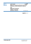
(PS=Pmax at 20˚C)
-10 to 90˚C
YOKOGAWA
ROTA YOKOGAWA, 79664 WEHR, Made in Germany
*1)
Figure 2.1.1 Data Plate (Integral Flowmeter Style)
F0201.EPS
-10 to 90˚C
YOKOGAWA
ROTA YOKOGAWA, 79664 WEHR, Made in Germany
*1)
F0202.EPS
Figure 2.1.2 Data Plate (Remote Flowtube Style)
*1) In case of "special pressure rating" (/Z) or for use in
fluid group 1 (/Z) 0038 may be described on the data
plate.
In case of sizes 15 to 25 mm (0.5 to 1 in.) 0038 is not
described on the data plate.
2-1
IM 01R21D01-01E-E
1st edition, April 2006
2. HANDLING PRECAUTIONS
2.2 Accessories
2.4 Installation Location
Precautions
Check that the parts shown below are included in
the package:
Select the installation location with consideration
to the following items to ensure long-term stable
operation of the instrument.
• Remote Flowtube size 15 to 1000 mm (0.5 to 40 in):
Hexagonal wrench: 2 piece (one each of
1.5 mm and 3 mm nominal sizes)
• Integral Flowmeter
Spare fuse (T2.0A, 250 V, T: time-lag fuse):
1pc. Use this spare fuse for this product
only.)
Hexagonal wrench: 2 piece (one each of
1.5 mm and 3 mm nominal sizes)
· Ambient Temperature:
Avoid installing the instrument in locations with
constantly fluctuating temperatures. If the
location is subject to radiant heat from the plant,
provide heat insulation or improve ventilation.
· Atmospheric Condition:
Avoid installing the instrument in a corrosive
atmosphere. In situations where this is
unavoidable, consider ways to improve ventilation
and to prevent rainwater from entering and being
retained in the conduit pipes.
· Vibrations or Shocks:
Avoid installing the instrument in a place subject
to shocks or vibrations.
2.3 Storage Precautions
If the instrument is to be stored for a long period of
time after delivery, observe the following points.
• The instrument should be stored in its original
packing condition in the storage location.
• Select a storage location that fulfills the
following conditions:
• A place where it will not be exposed to rain,
water and UV radiation also caused by sun
light.
• A place subject to minimal vibrations or shocks
• Temperature and humidity levels should be as
follows:
Temperature: 0 to 70 °C
Humidity: 5 to 80 % RH (no condensation)
The preferred ambient temperature and
humidity levels are 25 °C and approximately 65 % RH.
· If the RXF magnetic flowmeter is transferred to
the installation site and stored without being
installed, its performance may be impaired due
to the infiltration of rainwater and so forth. Be
sure to install and wire the RXF magnetic
flowmeter as soon as possible after transferring
it to the installation location.
IM 01R21D01-01E-E
1st edition, April 2006
2-2
3. INSTALLATION
3.
INSTALLATION
3.1 Piping Design Precautions
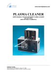
(3) Required Lengths of Straight Runs
To maintain accurate measurement, see EN 29104
(ISO 9104) “Measurement of fluid flow in closed
conduits” which explains the requirements for
upstream piping conditions of magnetic flowmeters.
WARNING
The piping conditions we recommend to our
customers as shown in Figure 3.1.1 are based on
JIS B7554 and on our piping condition test data.
Installation of the magnetic flowmeter must be
performed by expert engineers or skilled personnel. No operator shall be permitted to perform
procedures relating to installation.
Gate valve
fully open
IMPORTANT
5D or more
Tee
Design piping correctly, referring to the following
information to prevent damage to flowtubes and
to assure accurate measuring.
Reducer
pipe
D: Flowtube Size
Expander
pipe
2D
or more 0 is allowable. 0 is allowable. 10D or more 2D or more
90-degree bent
Various valves
2D
5D or more 0 is allowable. 5D or more 0 is allowable.10D or more or more
F08.EPS
Figure 3.1.1 Required Lengths of Straight Runs
*1: Do not install anything in the vicinity that may
interfere with the magnetic field, induced
signal voltages, or flow velocity distributions of
the flowmeter.
NOTE
This chapter describes the remote flowtube as an
example. The same attention must be paid to the
integral flowmeter.
*2: A straight run may not be required on the
downstream side of the flowmeter. However, if
a downstream valve or other fitting causes
irregularity or deviation in flows, provide a
straight run of 2D to 3D on the downstream
side.
(1) Location
IMPORTANT
Install the flowmeter in a location where it is not
exposed to direct sunlight, and where the
ambient temperature is between –40° to 60°C
(–40° to 140°F). The minimum ambient temperature is limited by the minimum fluid temperature
of the flowtube (the lining). For more information,
refer to Chapter 6 “OUTLINE”. The flowmeter
may be used in an ambient humidity where the
relative humidity ranges from 0 to 100 %. However, avoid long-term continuous operation at
relative humidity above 95 %.
*3: It is highly recommended to mount valves on
the downstream side so that deviated flows do
not occur in the flowtube and to avoid startup
from an empty condition.
IMPORTANT
Do not install the flowmeter where fluid conductivity tends to become unstable. If chemicals are
fed near the upstream side of a magnetic
flowmeter, they may affect the flow-rate’s indications. To avoid this situation, it is recommended
that the chemical feed ports are located on the
downstream side of the flowmeter. If it is unavoidable that chemicals must be fed on the
upstream side, provide a sufficient length of
straight run (approximately 50D) to ensure the
proper mixture of fluids.
(2) Noise Avoidance
IMPORTANT
The flowmeter should be installed apart from
electrical motors, transformers, and other power
sources in order to avoid interference with the
measurement.
3-1
IM 01R21D01-01E-E
1st edition, April 2006
3. INSTALLATION
(4) Maintaining Stable Fluid Conductivity
(Incorrect)
Upstream side
(9) Mounting Positions
• Pipes must be fully filled with liquids
(Correct)
Downstream side
IMPORTANT
It is essential that pipes remain fully filled at all
times, otherwise flow rate indications may be
affected and measurement errors may be
caused.
F0302.EPS
Figure 3.1.2 Chemical Injection
(5) Precautions for Use of Liquid Sealing
Compounds
Piping shall be designed so as to maintain the
interior of the flowtube filled with fluids.
IMPORTANT
Vertical mounting is effective in such cases as
when fluids tend to separate or solid matter may
be precipitated. When choosing vertical mounting,
direct the fluids from the bottom to the top to
ensure that the pipes remain fully filled.
Take care in using liquid sealing compounds on
the piping, as it may have a negative influence
on the flow indications by flowing out and
covering the surfaces of an electrode or
grounding ring. In particular, take care if a liquid
sealing compound is used in the case of vertical
piping.
(Correct)
(Incorrect)
(Correct)
h
h>0
(Incorrect)
h
h>0
(6) Service Area
Select locations where there is adequate space to
service installing, wiring, overhauling, etc.
F0304.EPS
Figure 3.1.4
(7) Bypass Line
It is recommended to install a bypass line to
facilitate maintenance and zero adjustment.
• Avoid air bubbles
IMPORTANT
Bypass valve
If air bubbles enter a measurement pipe, flow
rate indications may be affected and measurement errors may be caused.
Block valve
Block valve
Mounting Positions
In cases where fluids contain air bubbles, piping
must be designed to prevent them from
accumulating in the measurement pipe of a
flowtube.
F0303.EPS
Figure 3.1.3 Bypass Line
(8) Supporting the Flowmeter
If a valve exists near the flowmeter, try to mount
the flowmeter on the valve’s upstream side in order
to prevent a possible reduction of pressure inside
the pipe, thereby avoiding the possibility of air
bubbles.
CAUTION
Do not secure the flowmeter separately to prevent
the vibrations, shocks, and expansion and
contraction forces of the piping from affecting it.
Fix the pipes first, then support the flowmeter
with the pipes.
(Incorrect)
(Correct)
(Correct)
(Incorrect)
Valve
F10.EPS
Figure 3.1.5 Avoiding Air Bubbles
IM 01R21D01-01E-E
1st edition, April 2006
3-2
3. INSTALLATION
• Mounting orientation
CAUTION
In order to lift a magnetic flowmeter that is fitted
with eyebolts, proceed as in Figure 3.2.1. Never
lift it using a bar passed through the flowtube as
this damages the liner severely.
IMPORTANT
If electrodes are perpendicular to the ground, air
bubbles near the top or precipitates at the
bottom may cause measurement errors. Ensure
that the terminal box of a remote flowtube and
converter of an integral flowmeter are mounted
above the piping to prevent water from seeping
into them.
Correct
Incorrect
Incorrect
Air bubble
Electrode
Electrode
Precipitate
Water can
seep into
the terminal
box.
F0306.EPS
A horizontal position
Figure 3.1.6 Mounting Orientation
A vertical position, using
a block and tackle
F0307.EPS
3.2 Handling Precautions
Figure 3.2.1
Lifting Flowmeter
(2) Avoiding Shocks from Impact
WARNING
CAUTION
The magnetic flowmeter is a heavy instrument.
Be careful that no damage is caused to personnel through accidentally dropping it, or by
exerting excessive force on the magnetic flowmeter. When moving the magnetic flowmeter,
always use a trolley and have at least two
people carry it.
Take care not to drop the flowmeter or expose it
to excessive shock. In particular, be careful not
to subject the flange surface to shock. This may
lead to liner damage which will result in
inaccurate readings.
(3) Flange Protection Covers
NOTE
IMPORTANT
This chapter describes the remote flowtube as
an example. The same attention must be paid to
the integral flowmeter.
3.2.1
Keep the protective covering (i.e. the corrugated
cardboard or other cushioning material) in place
over the flange except when mounting the
flowmeter to the pipe.
General Precautions
(1) Precaution during Transportation
The magnetic flowmeter is packed tightly. When it
is unpacked, pay attention to prevent damaging the
flowmeter. To prevent accidents while it is transported to the installing location, transport it to the
site in its original packing.
3-3
IM 01R21D01-01E-E
1st edition, April 2006
3. INSTALLATION
(4) Terminal Box Cover
IMPORTANT
As it is possible that the insulation will deteriorate, do not open the terminal box cover until it is
time to wire it.
Slanted
Misaligned
F0308.EPS
Figure 3.2.2 Slanted and Misaligned Flowmeter
Piping
(5) Long-term Non-use
(2) Inside a newly installed pipeline, there may be
some unusual substances such as residue
from welding or wood chips. Remove them by
flushing the piping before mounting the
flowmeter. This prevents the lining from being
damaged, as well as the occurrence of
erroneous measured signals resulting from
foreign substances passing through the
flowtube during measurement.
IMPORTANT
It is not recommended to leave the flowmeter
unused for a long term after installation. If this
situation is unavoidable, take care of the
flowmeter by observing the following.
• Confirmation of sealing conditions for the
flowmeter
Confirm that the terminal box screw and wiring
ports are well sealed. Equip the conduit piping with
drain plugs or waterproof glands to prevent
moisture or water from penetrating into the
flowmeter through the conduit.
3.3 Mounting Procedures
NOTE
The tightening torque value to which gaskets
must be tightened varies depending on the type
and external dimensions of the lining and the
gasket. In this section, the tables indicating
tightening torque values include the corresponding
gasket types.
• Regular inspections
Inspect the sealing conditions as mentioned
above, and the inside of the terminal box at least
once a year. Also, due to rain, etc. when it is
suspected that water may have penetrated into the
inside flowmeter perform supplementary
inspections.
IMPORTANT
3.2.2
Use bolts and nuts in compliance with the flange
ratings. Be sure to choose a gasket with an inner
diameter that does not protrude inside the piping.
If the inner diameter of the gasket is too large,
however, fluid leakage may result.
Flowmeter Piping
CAUTION
Misaligned or slanted piping can lead to leakage
and damage to the flanges.
(1) Mounting Direction
Mount the flowmeter so that the flow direction of
the fluid to be measured is in line with the
direction of the arrow mark on the flowmeter.
(1) Correct any misaligned or slanted piping, and
any gaps that may exist between mounting
flanges before installing the flowmeter (refer to
Figure 3.2.2).
IM 01R21D01-01E-E
1st edition, April 2006
3-4
3. INSTALLATION
IMPORTANT
If it is impossible to match the direction of the
arrow mark, the direction of the electrical connection can be changed. Refer to Section 5.1 to do
this properly.
In case the fluid being measured flows against
the arrow direction, refer to the parameter
J20: Flow Direction in the user’s manual of the
RXFA11 Magnetic Flowmeter Remote Converter
(IM 01R21C01-01E-E) or the RXFA14 Magnetic
Flowmeter Remote Converter/RXF Integral
Flowmeter [Software Edition] (IM 01R21C02-01E-E).
(2) Tightening Nuts
Tighten the bolts according to the torque values for
the metal piping in Table 3.3.2. For PVC piping,
use rubber gaskets and tighten the nuts to the
torque values for the PVC piping in Table 3.3.1.
*Piping-side flange
*Gasket (two units)
*: These items must be provided by the user.
Choose nuts and bolts in compliance with
the flange ratings.
Flowmeter-side flange
*Bolt
*Nut
F0313.EPS
Figure 3.3.1
Mounting Procedure for Flange Style (size: 15 mm (0.5 in.) to 1000 mm (40 in.))
3-5
IM 01R21D01-01E-E
1st edition, April 2006
3. INSTALLATION
Table 3.3.1
Flange Style Tightening Torque Values for PVC Piping
Tightening torque values for Hard rubber lining type (N m / {kgf cm} / [in lbf])
Gasket types
Fluororubber gasket, chloroprene rubber gasket, or the equivalent in hardness
for user’s flange
Flange ratings
Size
DIN PN10
DIN PN16
DIN PN40
and ANSI Class 150,
and ANSI Class 300,
mm (in.)
0.9 to 1.6 / {9.177 to 16.32} / [7.966 to 14.16]
15 (0.5)
0.9 to 1.6 / {9.177 to 16.32} / [7.966 to 14.16] 0.9 to 1.6 / {9.177 to 16.32} / [7.966 to 14.16]
25 (1.0)
2.7 to 4.5 / {27.53 to 45.89} / [23.9 to 39.83]
2.7 to 4.5 / {27.53 to 45.89} / [23.9 to 39.83]
2.3 to 3.9 / {23.45 to 39.77} / [20.36 to 34.52]
32 (1.25)
3.0 to 4.9 / {30.59 to 49.97} / [26.55 to 43.37]
3.0 to 5.0 / {30.59 to 50.99} / [26.55 to 44.25]
2.9 to 4.9 / {29.57 to 49.97} / [25.67 to 43.37]
40 (1.5)
4.5 to 7.6 / {45.89 to 77.5} / [39.83 to 67.26]
4.7 to 7.8 / {47.93 to 79.54} / [41.6 to 69.03]
4.4 to 7.4 / {44.87 to 75.46} / [38.94 to 65.49]
50 (2.0)
5.9 to 9.8 / {60.16 to 99.93} / [52.22 to 86.74]
2.9 to 4.8 / {29.57 to 48.95 } / [25.67 to 42.48]
5.5 to 9.2 / {56.08 to 93.81 } / [48.68 to 81.43]
65 (2.5)
9.0 to 15.0 / {91.77 to 153.0} / [79.66 to 132.8]
4.4 to 7.3 / {44.87 to 74.44} / [38.94 to 64.61]
—
80 (3.0)
4.9 to 8.1 / {49.97 to 82.6} / [43.37 to 71.69]
5.5 to 9.1 / {56.08 to 92.79} / [48.68 to 80.54]
—
100 (4.0)
6.7 to 11.2 / {68.32 to 114.2} / [59.3 to 99.13]
7.5 to 12.6 / {76.48 to 128.5} / [66.38 to 111.5]
—
125 (5.0)
9.9 to 16.5 / {101.0 to 168.3} / [87.62 to 146.0]
10.7 to 17.8 / {109.1 to 181.5} / [94.7 to 157.5]
—
150 (6.0)
14.4 to 24.0 / {146.8 to 244.7} / [127.4 to 212.4] 9.8 to 16.3 / {99.93 to 166.2} / [86.74 to 144.3]
—
200 (8.0)
13.4 to 22.3 / {136.6 to 227.4} / [118.6 to 197.4] 14.6 to 24.3 / {148.9 to 247.8} / [129.2 to 215.1]
—
T0315.EPS
Table 3.3.2
Flange Style Tightening Torque Values for Metal Piping and Permeable Fluids
Tightening torque values for Hard rubber lining type (N m / {kgf cm} / [in lbf])
Gasket types
for user’s flange
Flange ratings
Size
mm (in.)
15 (0.5)
Non-asbestos gasket, PTFE-sheathed non-asbestos gasket, or the equivalent in hardness
DIN PN10
and ANSI Class 150,
6.9 to 7.9 / {70.36 to 80.56} / [61.07 to 69.92]
DIN PN16
and ANSI Class 300,
DIN PN40
7.0 to 8.1 / {71.38 to 82.6} / [61.95 to 71.69]
7.0 to 8.1 / {71.38 to 82.6} / [61.95 to 71.69]
25 (1.0)
19.6 to 22.5 / {199.9 to 229.4} / [173.5 to 199.1] 19.7 to 22.7 / {200.9 to 231.5} / [174.4 to 200.9] 17.5 to 20.1 / {178.5 to 205.0} / [154.9 to 177.9]
32 (1.25)
21.5 to 24.7 / {219.2 to 251.9} / [190.3 to 218.6] 21.6 to 24.8 / {220.3 to 252.9} / [191.2 to 219.5] 22.1 to 25.4 / {225.4 to 259.0} / [195.6 to 224.8]
40 (1.5)
32.5 to 37.4 / {331.4 to 381.4} / [287.6 to 331.0] 32.8 to 37.7 / {334.5 to 384.4} / [290.3 to 333.7] 33.8 to 38.9 / {344.7 to 396.7} / [229.2 to 344.3]
50 (2.0)
41.3 to 47.5 / {421.1 to 484.4} / [365.5 to 420.4] 20.6 to 23.7 / {210.1 to 241.7} / [182.3 to 209.8] 42.2 to 48.5 / {430.3 to 494.6} / [373.5 to 429.3]
65 (2.5)
61.2 to 70.4 / {624.1 to 717.9} / [541.7 to 623.1] 30.5 to 35.1 / {311.0 to 357.9} / [269.9 to 310.7]
—
80 (3.0)
34.2 to 39.3 / {348.7 to 400.7} / [302.7 to 347.8] 38.5 to 44.3 / {392.6 to 451.7} / [340.7 to 392.1]
—
100 (4.0)
45.2 to 52.0 / {460.9 to 530.3} / [400.0 to 460.2] 51.0 to 58.7 / {520.1 to 598.6} / [451.4 to 519.5]
—
125 (5.0)
66.8 to 76.8 / {681.2 to 783.1} / [591.2 to 679.7] 70.8 to 81.4 / {722.0 to 830.0} / [626.6 to 720.4]
—
150 (6.0)
93.9 to 108.8 / {957.5 to 1109} / [831.1 to 962.9] 65.4 to 75.2 / {666.9 to 766.8} / [578.8 to 665.6]
—
200 (8.0)
85.8 to 98.7 / {874.9 to 1006} / [759.4 to 873.6] 91.5 to 105.2 / {933.0 to 1073} / [809.8 to 931.1]
—
250 (10)
207.8 to 239.0 / {2119 to 2437} / [1839 to 2115] 222.9 to 256.3 / {2273 to 2614} / [1973 to 2268]
—
300 (12)
171.0 to 196.7 / {1744 to 2006} / [1513 to 1741] 184.1 to 211.7 / {1877 to 2159} / [1629 to 1874]
—
350 (14)
234.7 to 269.9 / {2393 to 2752} / [2077 to 2389] 261.3 to 300.5 / {2665 to 3064} / [2313 to 2660]
—
400 (16)
320.0 to 368.0 / {3263 to 3753} / [2832 to 3257] 343.2 to 394.7 / {3500 to 4025} / [3038 to 3493]
—
T0316.EPS
IM 01R21D01-01E-E
1st edition, April 2006
3-6
4. WIRING
4.
WIRING
4.1 Wiring the Integral
Flowmeter
four-core cables are used for wiring. Keep
conduits or flexible tubes watertight using
sealing tape.
• When waterproof glands or union equipped
waterproof glands are used, avoid tightening the
glands with an excessive torque.
• In case of 24 V power supply version, it comes
with a plug. Use this plug to cover the unused
wiring port when wiring the instrument with only
one, four-core cable.
• Be sure to turn the power off before opening
the terminal box cover.
• Before turning the power on, tighten the
terminal box cover securely.
• The terminal box cover is locked by the special
screw. In case of opening the terminal box
cover, use the hexagonal wrench attached. For
handling the locking screw refer to fig. 4.1.5.
• Be sure to lock the cover by the special screw
using the hexagonal wrench attached after
installing the cover. For handling the locking
screw refer to fig. 4.1.5.
This section describes the wiring of the integral
flowmeter.
WARNING
The wiring of the magnetic flowmeter must be
performed by expert engineer or skilled personnel. No operator shall be permitted to perform
procedures relating to wiring.
CAUTION
Once all wiring is complete, check the connections before applying power to the instrument.
Improper arrangements or wiring may cause a
unit malfunction or damage.
4.1.1
Wiring Precautions
4.1.2
Be sure to observe the following precautions when
wiring:
Power Cable / Output Cable
Use polyvinyl chloride insulated and sheathed
control cables (JIS C 3401) or polyvinyl chloride
insulated and sheathed portable power cables (JIS
C 3312) or the equivalent.
CAUTION
Outer Diameter: 6.5 to 12 mm (0.26 to 0.47 in.),
Nominal Cross Section (Single wire): 0.5 to 2.5mm2
Nominal Cross Section (Stranded wire):
0.5 to 1.5 mm2
In case of power cable, Green/Yellow covered
conductor shall be used only for connection to
PROTECTIVE CONDUCTOR TERMINALS.
Conform to IEC227, IEC245 or equivalent national
authorization.
• In cases where the ambient temperature
exceeds 50 °C (122 °F), use external heatresistant wiring with a maximum allowable
temperature of 70 °C (158 °F) or above.
• Do not connect cables outdoors in wet weather
in order to prevent damage from condensation
and to protect the insulation, e.g. inside the
terminal box of the flowmeter.
• All the cable ends must be provided with round
crimp-on terminals and be securely wired.
• The signal cables may be routed in separate
steel conduit tubes or flexible conduit tubes.
• If possible route the power and output signal
cables in separate steel conduit tubes, except
when the power supply voltage is 24 V and
4-1
IM 01R21D01-01E-E
1st edition, April 2006
4. WIRING
NOTE
• For power cables, always use a crimp terminal
with an insulation cover.
• Use crimp tools from the manufacturer of the
crimp terminal you want to use to connect the
crimp terminal and cable.
• Use crimp tools that are appropriate for the
diameter of the cable to be connected.
F0403.EPS
4.1.3
Wiring Ports
Figure 4.1.1
This instrument is of watertight construction as
stipulated in JIS C0920-1982. (Tests to prove
protection against ingress of water and degrees of
protection against ingress of solid objects for
electrical equipment.)
Plastic Gland
(3) Conduit Wiring
(1) When there are no particular optional
specifications
The wiring port is sealed with a plastic gland IP67.
Please remove sealing plug from gland entry
before wiring. At this time, handle the wiring port in
accordance with the JIS C0920-1982 mentioned
above.
Washer
Gasket
Waterproof gland
Cable
(2) Wiring using waterproof glands
Figure 4.1.2
F0401.EPS
Waterproof Gland
For working on the electric wire tubes or the
flexible tubes (PF1/2), use the waterproof gland
and attach them directly to the wiring port.
When mounting the conduits, pass the conduit
through the wiring connection port, and utilize the
waterproof gland to prevent water from flowing in.
Place the conduit pipe on an angle as shown in
Figure 4.1.3. Install a drain valve at the low end
of the vertical pipe, and open the valve regularly.
IMPORTANT
To prevent water or condensation from entering
the converter housing, waterproof glands are
recommended. Do not over-tighten the glands or
damage to the cables may result. Tightness of
the gland can be checked by confirming that the
cable is held firmly in place.
Drain valve
F0404.EPS
Figure 4.1.3
IM 01R21D01-01E-E
1st edition, April 2006
4-2
Conduit Wiring
4. WIRING
4.1.4
Wiring Connections
Table 4.1.1 Terminal Symbols
Terminal
Symbols
(1) Removing Cover
Loosen cover locking screw 2 clockwise using a
hexagonal wrench (nominal size 3 mm) to unlock
the cover. (Upon shipment from the manufacturing
plant, the cover is unlocked.) Hold the flowmeter
with your hand and remove the cover by turning it
in the direction of the arrow as shown below.
Description
Functional grounding
N/L/+
I+
IDO+
DODIO+
DIO-
Power supply
Current output 4 to 20mA DC
Pulse output/Alarm output/
Status output
Alarm output/Status output
Status input
Protective grounding
(Outside of the terminal)
T0401.EPS
(3) Precautions for Wiring of Power Supply
Cables
When connecting to the power supply, observe the
points below. Failure to comply with these
warnings may result in an electric shock or
damage to the instrument.
s2
s1
WARNING
Cover locking
screws
• Ensure that the power supply is OFF in order to
prevent electric shocks.
• Ensure the protective grounding terminal is
grounded with a grounding resistance of 100 V
or less before turning the power on.
• Use insulating sleeve crimp terminals (for 4-mm
screws) for the power supply wiring and protective grounding wiring.
• Install an external switch or circuit breaker as a
means to turn the powe off (capacitance; 15A,
conforming to IEC947-1 and IEC947-3). Locate
this switch either near the instrument or in other
places facilitating easy operation. Affix a “Power
Off Equipment” label to this external switch or
circuit breaker.
F0405.EPS
Figure 4.1.4
Removing the Terminal Box Cover
POWE
SUPPLY
-
DIO
+
-
D
+
-
I
+ L/+ N/ -
(2) Terminal Configuration
When the cover is removed, the connection
terminals will be visible.
Wiring Procedure
1. Turn the instrument's power off.
2. Wire the power supply cable and the functional
grounding cable to the power supply terminals.
POWE
SUPPLY
F0406.EPS
+
Terminal Configuration
-
I
Figure 4.1.5
L/+ N/
-
Functional grounding cable
Power supply
cable
-
DIO
+
-
D
+
The description of the terminal symbols is shown
in Table 4.1.1.
F0407.EPS
Figure 4.1.6
4-3
Electric Cable Wiring
IM 01R21D01-01E-E
1st edition, April 2006
4. WIRING
(4) DC Power Connection
When using DC power as the power supply for the
converter, give attention to the following points.
1)
(5) Grounding
CAUTION
Connecting Power Supply
Be sure to connect the protective grounding of
the RXF integral flowmeter with a cable of 2mm2
or larger cross section in order to avoid electrical
shock to the operators and maintenance engineers and to prevent the influence of external
noise.
Connect the grounding wire to the mark. The
grounding should satisfy Class D requirements
(ground resistance, 100 Ω or less).
IMPORTANT
Do not connect power supply with reversed
polarities.
L/+ terminal: connect +
N/– terminal: connect –
2)
Required Power Supply Voltages
• The protective grounding terminals
are
located on the inside and outside of the
terminal area. Either terminal may be used.
• Use 600-V vinyl insulation wires as the
grounding wires.
IMPORTANT
When using a 24 V power supply, the specification for the supply voltage is 24 V (–15% to
+20%), but the input voltage of the converter
drops due to cable resistance therefore it must
be used within the following ranges.
Allowable cable length m(ft)
Supply Voltage and Cable Length
1000 (3300)
900 (2970)
800 (2640)
700 (2310)
600 (1980)
500 (1650)
400 (1320)
300 ( 990)
200 ( 660)
100 ( 330)
0
Protective grounding
terminals
F0409.EPS
20
Figure 4.1.7
22
24
26
28
Usable voltage range (V)
Cable cross section area: 1.25 mm2
Cable cross section area: 2 mm2
Protective Grounding Terminal Location
IMPORTANT
F0408.EPS
3)
Improper grounding can have an adverse effect
on the flow measurement. Ensure that the
instrument is properly grounded.
Setting Power Supply Frequency
IMPORTANT
IMPORTANT
Set the local power frequency in order to eliminate the effect of induction noise from the power
supply.
Refer to “Chapter 6: Parameter Description” in
the user’s manual of the RXF Integral Flowmeter
[Software Edition] (IM 01R21C02-01E-E).
Parameter No.: J30 and J31
IM 01R21D01-01E-E
1st edition, April 2006
In situations where a DC power supply is used
for converters, set the local commercial power
frequency in area where the converter is installed.
Set “No” for J30: Power Synch and the local
commercial power frequency for J31: Power
Frequency.
4-4
4. WIRING
·
The electromotive force of the magnetic flowmeter
is very small and it is easily affected by noise, and
the reference electric potential is the same as that
of the measuring fluid. Therefore, the reference
electric potential (terminal potential) of the flowtube
and converter also need to be the same as that of
the measuring fluid. Moreover, the potential must
be the same as the ground. The magnetic flowmeter comes standard without grounding electrodes
[RXF
1N...], but grounding electrode models
are available [RXF
1L(H).. Please check your
model code].
RXF integral flowmeter
l+
l-
Receiver
Instrument
Resistive load max. 750 Ω.
(When using BRAIN/ HART communication,
more than 250 Ω , less than 600Ω ).
F0411.EPS
Figure 4.1.9
·
In case you have no grounding electrode you
must provide a connection with the charge of
the measured fluid to the protective grounding
terminal shown in figure 4.2.12. Without this
connection proper function can not be
guaranteed.
4-20 mA DC Output Connection
Pulse Output
IMPORTANT
• As this is a transistor contact (isolated type),
give attention to proper voltage and polarity
when wiring.
• Do not apply a voltage larger than 30 V DC or
a current larger than 0.2 A in order to prevent
damage to the instrument.
• When input filter constant of the electronic
counter is large in relation to the pulse width,
the signal will decrease and the count will not
be accurate.
• If the input impedance of the electronic counter
is large, an induction noise from the power
supply may result in inaccurate counts. Use a
shielded cable or sufficiently reduce the input
impedance of the electronic counter within the
electromagnetic flowmeter pulse output specification range.
• The active pulse output (optional code /EM)
cannot be used in conjunction with the standard
pulse output.
• When the active pulse output (optional code /EM)
is selected, do not short-circuit the DO+ and
DO– terminals to avoid damaging the instrument.
• To avoid communication (BRAIN/ HART)
failure, it is recommended to use the shield
cable.
Additionally be sure to ground also according to
Figure 4.1.8.
600 V vinyl-insulated cable
(2 mm2 or larger)
• Class D requirements (ground resistance,
100 Ω or less).
F0410.EPS
Figure 4.1.8
4-20 mA DC Output
Grounding
(6) Connecting to External Instruments
WARNING
Before wiring with external instruments, be sure
to turn off the magnetic flowmeter and any
external instruments.
Connect the RXF integral flowmeter terminal to
external instruments, giving attention to the following
points.
NOTE
For pulse output from the DO terminals, parameters B32, B33 and F20 must be set. Refer to
“Parameter Description” in the user’s manual of
the RXF Integral Flowmeter [Software Edition] (IM
01R21C02-01E-E).
4-5
IM 01R21D01-01E-E
1st edition, April 2006
4. WIRING
NOTE
Protective diode
RXF integral flowmeter DO+
For status input to the DIO terminals, parameter
F21 must be set. Refer to “Parameter
Description” in the user’s manual of the RXF
Integral Flowmeter [Software Edition] (IM
01R21C02-01E-E).
Mechanical Counter
PULSE OUT
DO-
RXF integral flowmeter DO+
PULSE OUT
Electronic Counter
Load
DO-
· Status Output/ Alarm Output
30V DC, 0.2A. max
F0412.EPS
Figure 4.1.10 Pulse Output Connection
RXF integral flowmeter
PULSE OUT
IMPORTANT
Since this is an insulated transistor output, be
careful of voltage and polarity when wiring. Do
not apply a voltage larger than 30 V DC or a
current larger than 0.2 A in order to prevent
damage to the instrument.
This output cannot switch an AC load. To switch
an AC load, an intermediate relay must be
inserted as shown in Figure 4.1.13.
*The alarm output operates from open (normal)
to closed (alarm occurrence) in the default value
(as setup upon plant shipment). Changes can
be made via the parameter settings.
Protective diode
DO+
Mechanical Counter
DO-
RXF integral flowmeter DO+
PULSE OUT
DO-
Electronic Counter
Load
Output voltage: 24 V DC ±20%
• Current: 30 to 150 mA
Pulse rate: 0.0001 to 2 pps
Pulse width: 20, 33, 50, 100 ms
F0413.EPS
Figure 4.1.11 Active Pulse Output (/EM)
· Status Input
Protective diode
RXF integral flowmeter DO+ (or DIO+)
Load
DO- (or DIO-)
IMPORTANT
This connection is not possible.
Status inputs are designed for use with novoltage (dry) contacts. Be careful not to connect
the status to any signal source carrying voltage.
Applying voltage may damage the input circuit.
RXF integral flowmeter DO+ (or DIO+)
DO- (or DIO-)
External power supply
30V DC, 0.2A. max
Closed:
Open:
Electromagnetic
valve
AC power supply
F0415.EPS
Less than 200 Ω
More than 100 kΩ
DIO+
Relay
Figure 4.1.13 Status Output/Alarm Output Connection
RXF integral flowmeter
NOTE
For status and alarm outputs from the DO or DIO
terminals, parameters F20 or F21 must be set.
Refer to “Parameter Description” in the user’s
manual of the RXF Integral Flowmeter [Software
Edition] (IM 01R21C02-01E-E).
DIONo-voltage status input
F0414.EPS
Figure 4.1.12 Status Input Connection
IM 01R21D01-01E-E
1st edition, April 2006
4-6
4. WIRING
4.2.1
(7) Installing the Cover
Install the cover to the flowmeter by turning it in
the direction of the arrow as shown below. Tighten
cover locking screw 2 counterclockwise using a
hexagonal wrench (nominal size 3 mm) to lock the
cover.
Wiring Precautions
Be sure to observe the following precautions when
wiring:
CAUTION
• In cases where the ambient temperature
exceeds 50 °C (122 °F), use external heatresistant wiring with a maximum allowable
temperature of 70 °C (158 °F) or above.
• Do not connect cables outdoors in wet weather
in order to prevent damage from condensation
and to protect the insulation, e.g. inside the
terminal box of the flowtube.
• Do not splice the cable between the flowtube
terminal and the converter if it is too short.
Replace the short cable with a cable that is the
appropriate length.
• All the cable ends must be provided with round
crimp-on terminals and be securely wired.
• The signal cables may be routed in separate
steel conduit tubes or flexible conduit tubes.
• Keep conduits or flexible tubes watertight using
sealing tape.
• Ground the remote flowtube and the converter
separately (with grounding resistance of 100Ω
or less)
• Cover each shield of the signal cable with vinyl
tube or vinyl tape to avoid contact between two
shields or between a shield and a case.
• When waterproof glands or union equipped
waterproof glands are used, avoid tightening the
glands with an excessive torque.
• Be sure to turn the power off before opening
the terminal box cover.
• Before turning the power on, tighten the
terminal box cover securely.
• The terminal box cover of size 15 mm to 1000
mm is locked by the special screw. In case of
opening the terminal box cover, use the hexagonal wrench attached. For handling the
locking screw, refer to Figure 4.2.8.
• Be sure to lock the cover of size 15 mm to
1000 mm by the special screw using the
hexagonal wrench attached after installing the
cover. For handling the locking screw, refer to
Figure 4.2.20.
• When submersible type or optional code DHC is
selected, waterproof glands, signal and
excitation cables are attached and potted. In
order to preserve the effectiveness of waterproof
features, the terminal box cover and waterproof
glands must not be detached from flowmeter.
Cover locking
screws
F0416.EPS
Figure 4.1.14 Installing the Terminal Box Cover
4.2 Wiring the Remote
Flowtube
This section describes the wiring of the remote
flowtube only. For information relating to the wiring
of the converter, refer to the user’s manual of the
RXFA11 Magnetic Flowmeter Remote Converter
(IM 01R21C01-01E-E) or the RXFA14 Magnetic
Flowmeter Remote Converter (IM 01R21C02-01E-E).
WARNING
The wiring of the magnetic flowmeter must be
performed by expert engineer or skilled personnel. No operator shall be permitted to perform
procedures relating to wiring.
CAUTION
Once all wiring is complete, check the connections before applying power to the instrument.
Improper arrangements or wiring may cause a
unit malfunction or damage.
4-7
IM 01R21D01-01E-E
1st edition, April 2006
4. WIRING
Cables
Dedicated Signal Cable RXFC
B
C
90 (3.54)
L (Specified Dimensions)
Figure 4.2.1
55 (2.17)
90 (3.54)
8 (0.3) max.
F0417.EPS
150+5
(5.9)
On the
converter
side
Black
Red
On the
flowtube
side
∅10.5 (0.4)
Shield (C)
Insulation
Insulation
150+5
10.5 (0.413")
White
Red
Black
(5.9)
8(0.3) max.
White
Outer jacket
60 (2.36)
70 (2.76)
C
Conductors (A and B)
Shields (SA and SB)
Tape
SB
50 (1.97)
B
SA
A
(1) Dedicated Signal Cable (RXFC)
A
Unit: mm
(approx. in.)
25 (0.98)
4.2.2
20 (0.8)
RXFC
The flow signal is transmitted via this dedicated
cable. The cable is constructed with double
shielding over the two conductors, and heatresistant vinyl is used for the outer jacket material.
F0418.EPS
Figure 4.2.2
Finished diameter:
10.5 mm (0.413")
Maximum length:
Combination with the RXFA11 converter:
200 m (660 ft)
Combination with the RXFA14 converter:
100 m (330 ft)
Maximum temperature: 80 °C (176 °F)
Treatment of Dedicated Signal Cables
CAUTION
• As crimp terminals A, B, SA, SB and C have
their own electrical potentials, securely insulate
them so as not to come in contact with one
another.
• To prevent a shield from coming in contact with
another shield or the case, cover each shield
with a vinyl tube or wrap it in vinyl tape.
NOTE
Conductors A and B carry the signal from the
electrodes, and C is at the potential of the liquid
(signal common). Shields SA and SB are kept at
the same potentials as the individual electrodes
(these are actively driven shields.) This is done
to reduce the effect of the distributed capacitance
of the cable at long cable length. Note that, since
the signals from the individual electrodes are
impedance converted inside the converter, errors
will result if they come in contact with any other
component. Great care must be taken in the
cable end treatment.
(2) Excitation Cable
Use polyvinyl chloride insulated and sheathed
control cables (JIS C 3401) or polyvinyl chloride
insulated and sheathed portable power cables (JIS
C 3312) or the equivalent.
Outer Diameter: 6.5 mm to 12 mm (0.26 to 0.47 in),
Nominal Cross Section (Single wire): 0.5 to 2.5mm2
Nominal Cross Section (Stranded wire): 0.5 to 1.5
mm2
IMPORTANT
85 (3.35)
If the cable is longer than required, cut off any
extra length rather than coiling it up, and terminate the conductors as shown in Figure 4.2.2.
Avoid using junction terminal boards to extend
the cable length, as this will interrupt the shielding.
On the converter side
EX2
EX1
EX2
EX1
Unit : mm
(approx. in.)
Crimp terminal
85 (3.35)
On the flowtube side
F0419.EPS
Figure 4.2.3
IM 01R21D01-01E-E
1st edition, April 2006
4-8
End Treatment of Excitation Cable
4. WIRING
NOTE
• For excitation cables, always use a crimp
terminal with an insulation cover.
• Use crimp tools from the manufacturer of the
crimp terminal you want to use to connect the
crimp terminal and cable.
• Use crimp tools that are appropriate for the
diameter of the cable to be connected.
Washer
Gasket
Waterproof gland
Cable
4.2.3
Figure 4.2.5
Wiring Ports
F0420.EPS
Waterproof Gland
(3) Conduit Wiring
For working on the electric wire tubes or the
flexible tubes (PF1/2), remove the waterproof
gland and attach them directly to the wiring port.
When mounting the conduits, pass the conduit
through the wiring connection port, and utilize the
waterproof gland to prevent water from flowing in.
Place the conduit pipe on an angle as shown in
Figure 4.2.6. Install a drain valve at the low end
of the vertical pipe, and open the valve regularly.
This instrument is of watertight construction as
described in JIS C0920-1982. (Tests to prove
protection against ingress of water and degrees of
protection against ingress of solid objects for
electrical equipment.)
(1) When there are no particular optional
specifications
The wiring port is sealed with a plastic gland IP67.
Please remove sealing plug from gland entry
before wiring. At this time, handle the wiring port in
accordance with the JIS C0920-1982 mentioned
above.
Drain valve
F0423.EPS
Figure 4.2.6
Waterproof gland
Conduit Wiring
F0422.EPS
Figure 4.2.4
Plastic Gland
(2) Wiring using waterproof glands
IMPORTANT
To prevent water or condensation from entering
the converter housing, waterproof glands are
recommended. Do not over-tighten the glands or
damage to the cables may result. Tightness of
the gland can be checked by confirming that the
cable is held firmly in place.
4-9
IM 01R21D01-01E-E
1st edition, April 2006
4. WIRING
4.2.4
Wiring Connections
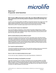
(3) Wiring the Remote Flowtube (General
Purpose Use, Submersible Style) with
Converters
(1) Removing Cover
Loosen the cover locking screw clockwise using a
hexagonal wrench (nominal size 3 mm) to unlock
the cover. (Upon shipment from the manufacturing
plant, the cover is unlocked.) Hold the flowtube
with your hand and remove the cover by turning it
in the direction of the arrow as shown below.
1) Connection with the RXFA11 converter
Connect wiring as shown in the figure below.
I+
I–
CURRENT OUT
SO1+ SO2+ COM
STATUS OUT
N/–
L/+
POWER SUPPLY
EX1
EX2
EXCIT ATION
AL+
AL–
ALARM OUT
C
SA
A
SIGNAL
B
SB
RXFA11 converter
FUSE
2.5A 250V
P+
P–
PULSE OUT
SI1+
SI2+
COM
STATUS IN
Excitation cable
A
Remote
flowtube
Taping*
A
B
Taping*
C
EX1
EX2
EX2
B
EX1
C
RXFC dedicated
signal cable
Remote flowtube
Figure 4.2.8
Removing the Terminal Box Cover (Remote
Flowtube)
SA
A
B
SB
C
EX1
EX2
* Individually tape and insulate the
shields corresponding to SA and
SB on the remote flowtube side.
F0426.EPS
F0424.EPS
Figure 4.2.7
Converter
Wiring Diagram
2) Connection with the RXFA14 converter
Connect wiring as shown in the figure below.
(2) Terminal Configuration remote flowtube
When the cover is removed, the connection
terminals will be visible.
R XF A14 converter
E X1
General style :
E X2
E xcitation cable
C
Terminal
Symbols
A
B
C
EX1
EX2
R XF C dedicated
s ignal cable
Description
SA
Flow signal output
A
B
Excitation current input
SB
Protective grounding
(Outside of the terminal)
R emote
flowtube
T aping*
F0425.EPS
Figure 4.2.9
Terminal Configuration
A
E X2
B
E X1
C
R emote flowtube
A
B
T aping*
C
EX1
EX2
C onverter
SA
A
B
SB
C
E X1
E X2
* Individually tape and insulate the
shields corresponding to SA and
SB on the remote flowtube side.
F 0427.E P S
Figure 4.2.11 Wiring Diagram
CAUTION
Before wiring, be sure that the RXFA11 or
RXFA14 converter has been turned off to prevent
an electrical shock.
IM 01R21D01-01E-E
1st edition, April 2006
4-10
4. WIRING
(4) Grounding
600 V vinyl insulated
electric cable
(2 mm2 or larger)
CAUTION
Be sure to connect the protective grounding of
the RXF remote flowtube with a cable of 2mm2 or
larger cross section in order to avoid electrical
shock to the operators and maintenance engineers and to prevent the influence of external
noise.
Connect the grounding wire to the
mark.
The grounding should satisfy Class D require
ments (ground resistance, 100 Ω or less).
Class D requirements (ground resistance 100 Ω or less)
F0430.EPS
Figure 4.2.12 Protective Grounding Terminal Location
IMPORTANT
Improper grounding can have an adverse affect
on the flow measurement. Ensure that the
instrument is properly grounded.
(5) Installing the Cover
Install the cover to the flowtube by turning it in the
direction of the arrow as shown below. Tighten the
cover locking screw counterclockwise using a
hexagonal wrench (nominal size 3 mm) to lock the
cover.
The electromotive force of the magnetic flowmeter
is minute and it is easy to be affected by noise.
And also that reference electric potential is the
same as the measuring fluid potential. Therefore,
the reference electric potential (terminal potential)
of the flowtube and the converter also need to be
the same as the measuring fluid. Moreover, that
the potential must be the same with ground. The
magnetic flowmeter comes standard without
grounding electrodes [RXF
1N...], but
grounding electrode models are available [RXF
1L(H).. Please check your model code].
In case you have no grounding electrode you
must provide a connection with the charge of
the measured fluid to the protective grounding
terminal shown in figure 4.2.12. Without this
connection proper function can not be
guaranteed.
F0431.EPS
Figure 4.2.13 Installing the Terminal Box Cover (Remote
Flowtube)
Additionally be sure to ground also according to
Figure 4.2.12.
4-11
IM 01R21D01-01E-E
1st edition, April 2006
4. WIRING
IM 01R21D01-01E-E
1st edition, April 2006
4-12
5. MAINTENANCE
5.
MAINTENANCE
WARNING
• Maintenance work must be carried out by
expert engineer or skilled personnel and not by
operators.
• Before opening the cover, it is important to
ensure that at least 10 minutes have passed
since the power was turned off. Furthermore,
opening of the cover must also be carried out
by expert engineer or skilled personnel.
CAUTION
• The terminal box cover is locked by the special
screw. In case of opening the terminal box
cover, use the hexagonal wrench attached.
• Be sur to lock the cover by the special screw
using the hexagonal wrench attached after
installing the cover.
F0501.EPS
(4) Using the hexagonal wrench, loosen the screw in the
neck.
(5) Turn the converter or the terminal box in the desired
direction.
5.1 Changing Direction of
Electrical Connection
NOTE
The converter and the terminal box can be
turned –140° to +180° from the arrow mark
indicating the flow direction. Do not exceed these
angle.
IMPORTANT
(6) Using the hexagonal wrench, retighten the neck screw.
The following types can not be changed direction
of electrical connection after delivery.
• Submersible Type (RXF
W-...)
• Optional code /DHC (for condensation-proof).
(1) The following tools are required to change the direction
of the parts for the electrical connection:
•
Hexagonal wrench (nominal size 1.5): Comes with
•
Wrench (size 46mm)
the instrument.
(2) Turn off the power to the flowmeter.
(3) Using the wrench, loosen thel nut at the neck of the
instrument.
F0502.EPS
(7) Using the wrench, retighten the nut at the neck. After that,
check that the converter or terminal box is fixed.
5-1
IM 01R21D01-01E-E
1st edition, April 2006
5. MAINTENANCE
5.2 Components Replacement (Integral
Flowmeter Only)
(2) The fuse can be seen after step (1). Remove
the fuse from the fuse holder.
(3) Push a new fuse into the holder until it clicks.
(4) Reinstall the amplifier assembly by following
the procedures shown in Section 5.2.3.
Spare fuses are shipped with the instrument.
WARNING
Fuse
• Component replacement and the associated
operations must be carried out by expert
engineer or skilled personnel and not by
operators.
• Before opening the cover, it is important to
ensure that at least 10 minutes have passed
since the power was turned off. Furthermore,
opening of the cover must also be carried out
by expert engineer or skilled personnel.
IMPORTANT
F0515.EPS
Figure 5.2.1 Fuse Replacement
• As a rule, maintenance of this flowmeter should
be implemented in a maintenance service shop
where the necessary tools are provided.
• The amplifier assembly contains sensitive parts
that may be damaged by static electricity.
Take care so as not to directly touch the
electronic parts or circuit patterns on the board,
for example, by preventing static electrification
by using grounded wrist straps when handling
the assembly. Also take precautions such as
placing a removed amplifier assembly into a bag
with an antistatic coating.
5.2.1
5.2.2
5.2.2.1
Display Unit Replacement
Removing the Display Unit
(1) Turn off the power.
(2) Loosen cover locking screw 1 clockwise using
a hexagonal wrench (nominal size 3) to unlock
the cover. (Upon shipment from the
manufacturing plant, the cover is locked.) Hold
the flowmeter with your hand and remove the
cover by turning it in the direction of the arrow
as shown below.
Fuse Replacement
CAUTION
Be sure to turn off the power before performing
fuse replacement. Also be sure to use the spare
fuse that was supplied with the product, or ones
supplied by Yokogawa’s sales or service offices.
Fuse type : T 2.5A, 250V, T, time-lag fuse
1
2
Cover locking screws
The fuse holder is located on the farthest circuit
board from the front.
F0516.EPS
Figure 5.2.2 Removing the Display Cover
(1) Remove the amplifier assembly by following the
procedures shown in Section 5.2.3 “Amplifier
Replacement.”
IM 01R21D01-01E-E
1st edition, April 2006
(3) Hold the display unit with your hand and remove
the two mounting screws. Remove the connector
of the display unit by pulling it to the left, taking
care not to damage it (refer to Figure 5.2.3).
5-2
5. MAINTENANCE
5.2.2.2
Assembling the Display Unit
5.2.2.4
(1) Reconnect the keyed display connector
according to figure 5.2.3.
Installing the Cover
(1) Install the cover to the flowmeter by turning it
in the direction of the arrow as shown below.
Tighten cover locking screw 1 counterclockwise
using a hexagonal wrench (nominal size 3) to
lock the cover.
(2) Secure the display unit using its two mounting
screws.
(3) Replace the cover by following the procedures
used to remove it in the reverse order.
Connector
1
2
Cover locking
screws
F0518-2.EPS
Figure 5.2.5 Installing the Display Cover
Display unit
mounting screws
(two screws)
F0517.EPS
5.2.3
Figure 5.2.3 Removing and Assembling the Display
Unit
5.2.2.3
Amplifier Replacement
IMPORTANT
Changing the Display Unit
Orientation 90°
In case of amplifier replacement, it is necessary
to perform the parameter resetting.
For parameters, refer to Chapter 6: Parameter
Description of IM 01R21C02-01E.
(1) Hold the display unit with your hand and
remove the two mounting screws.
(2) Turn the display unit 90° clockwise and confirm
the assembling position, taking care of the
connector and wire of the display unit.
5.4.3.1
(3) Secure the display unit using its two mounting
screws.
Removing the Amplifier Assembly
(1) Turn off the power.
(2) Remove the cover.
(3) Remove wiring connectors 1 and 2 (refer to
Figure 5.2.6) from the amplifier assembly.
Remove them carefully, without applying
excessive force.
Connector
(4) Loosen the three mounting screws while
holding the assembly with your hand.
(5) Pull the assembly straight out.
5.4.3.2
(1) To replace the amplifier assembly, follow the
procedures used to remove it in the reverse order.
Display unit
mounting
screws
(two screws)
Clockwise 90°
Figure 5.2.4 Assembling the Display Unit
Assembling the Amplifier Assembly
(2) Replace the assembly by pushing it in, taking
care not to damage the amplifier mounting
connectors on the circuit board.
F0518-1.EPS
5-3
IM 01R21D01-01E-E
1st edition, April 2006
5. MAINTENANCE
(3) Carefully connect wiring connectors 1 and 2 to
the amplifier assembly, making sure that the
connectors’ directions are correct. Let wiring
connector 2 pass along the amplifier side of
the rod.
5.3 Setting of Switches
(Integral Flowmeter
Only)
(4) Tighten the three mounting screws while
holding the assembly with your hand.
5.3.1
Setting of Burnout Switch
The burnout function sets the direction of current
output in situations where the CPU has become
damaged. Upon shipment from the manufacturing
plant, the burnout direction is set to High (i.e.25 mA);
the output direction can also be set to Low (i.e. 0
mA).
(5) Replace the cover, taking care not to entangle
the cables of the wiring connectors.
Modification of the burnout direction must be
carried out using the setting switch from the
amplifier’s CPU board (i.e., Switch 1) (See Figure
5.3.1).
Wiring connector 1
Table 5.3.1
Amplifier mounting
screw (three units)
Output Setting Pins for Burnout
Position of
Pin
Low
Low
Burnout
Direction
Burnout
Output
High
25 mA
Set to High before
shipment
Low
0 mA
Set to Low
High
Remarks
High
T0501.EPS
NOTE
On the amplifier’s CPU board, the burnout setting
switch (i.e., Switch 1) and the write protect switch
(i.e., Switch 2) are located adjacent to each
other. Accordingly, special care should be taken
when making switch settings.
Wiring connector 2
Low
Switch 1
Switch 2
Enable
High
2 ← Burnout setting switch
1 ← Write protect setting switch
Protect
Amplifier mounting
connectors
Wiring connector 1
Rod
F0520.EPS
Figure 5.3.1 Switch Configuration
Wiring connector 2
F0519.EPS
Figure 5.2.6 Assembling the Amplifier
IM 01R21D01-01E-E
1st edition, April 2006
5-4
5. MAINTENANCE
5.3.2
Setting of Write Protect Switch
(1) Excitation Coil Check (Remote Flowtube Only)
Check that there is continuity between terminals
EX1 and EX2 in the terminal box. If there is no
continuity, the coils may be broken and replacement or repair of the flowtube is necessary. The
coil resistance is designed to be 150 Ω or less. If
it is not, this may be an abnormal condition.
Consult Yokogawa’s sales or service offices.
By setting the write protect function to “Protect” it
is possible to prevent the overwriting of parameters.
Write protection can be carried out using either the
hardware switch on the CPU board (i.e., Switch 2)
or software parameter settings. If either of these
items is set to “Protect,” the overwriting of
parameters will be prohibited.
(2) Insulation Resistance Check (Remote
Flowtube Only)
Check the insulation resistances in the terminal
box in accordance with the tables below. If any of
them falls below the values listed in the tables,
consult Yokogawa’s sales or service offices for
investigation. If the insulation resistance cannot be
restored, replacement or repair of the flowtube is
needed. In case of submersible type flowmeters,
undo the wiring connection on the converter side
and measure resistance at the cable terminals.
This check is also recommended for general
purpose use remote flowtube if you like to include
the wiring in the integrity check of the flowtube.
NOTE
If the hardware switch is set to “Protect,” it will
not be possible to overwrite parameters; furthermore, this condition will be maintained until the
switch is set to “Enable.”
For more details regarding usage of the write
protect function and the software’s parameter
switches, refer to “Chapter 6: Parameter
Description” in the user’s manual of the RXF
Integral Flowmeter [Software Edition]
(IM 01R21C02-01E-E).
Coil Circuit
Checking is possible even if the pipe is filled with fluid.
5.4 Regular Inspection
Items
Test Terminals
Between terminals
EX1 and C
Test Voltage
Specification
500 V DC (Use an insulation
tester or the equivalent.)
1 MΩ or more
T050601.EPS
(1) Inspection of moisture-proofing inside the
terminal box: Once/year
Signal Circuit
Before testing, be sure to empty and dry the
interior of the pipe, checking that there is no
adhesive material. Also undo the wiring connection
on the converter side before testing.
(2) Retightening of piping joint screws: About
twice/year
(3) Inspection of electrodes and lining (in case of
adhesive and/or abrasive fluids, etc.)
Determine the period of regular inspection as
necessary.
Test Terminals
Between terminals
A and C
Between terminals
B and C
Test Voltage
Specification
500 V DC (Use an insulation
tester or the equivalent.)
100 MΩ or
more for each
T050602.EPS
5.5 Excitation Coil and
Insulation Resistance
Check (Remote
Flowtube Only)
CAUTION
• Before checking of the excitation coil and the
insulation resistance, be sure that the power
supply for RXFA11 or the RXFA14 converter has
been turned off.
• Before checking, be sure to disconnect the
cables from the terminals of the remote flowtube.
5-5
IM 01R21D01-01E-E
1st edition, April 2006
5. MAINTENANCE
5.6 Troubleshooting
Although magnetic flowmeters rarely require maintenance, failures may occur when
the instrument is not operated correctly. This section describes troubleshooting
procedures where the cause of the breakdown is identified through receiver
indication.
5.6.1
No Indication
START
Is an error being displayed? Check the converter display.
Is an error being
displayed?
YES
Refer to the “Alarm Functions” in
the RXFA11, RXFA14, and RXF
Integral Flowmeter [Software
Edition] user manuals.
NO
Is anything else
being displayed?
NO
YES
Is the fuse blown?
NO
YES
Does the
display return when the fuse
is replaced?
NO
YES
Does the
arrow on the tube match the
flow direction?
End
NO
Perform either of the following:
a. Reinstall the flowtube in
order to make the arrow and
flow direction match.
b. Reverse the setting for the
flow direction,parameter J20.
YES
Check whether the flowtube
is filled with fluid.
Is the flowtube
full of fluid?
NO
YES
Change the piping or the
mounting condition so that
the tube fills with the fluid.
Check the resistance between
the flowtube’s A, B, and C
terminals using a multimeter.*1
Is the
resistance 100 MΩ or more
in each case?
NO
YES
Remove the tube and
inspect the inside of the pipe.
Is foreign
material adhering to
the walls?
*1: Refer to Section 5.5 for how to check
the resistance of the remote style
flowtube. The integral flowmeter's
resistance cannot be checked.
NO
YES
Remove the foreign material.
Contact a service center.
F0521.EPS
IM 01R21D01-01E-E
1st edition, April 2006
5-6
5. MAINTENANCE
5.6.2
Unstable Zero
START
Investigate whether or not the flowtube
is filled with fluid and that it is free of
bubbles.
Is the flowtube
completely full of fluid?
Particular care must be taken in the case
of horizontal mounting. In order to ensure
complete filling of the tube, either adjust
the mounting position or switch to vertical
mounting.
NO
YES
Are there bubbles
in the fluid?
YES
Install a defoaming device on the
flowtube’s upstream side.
NO
Check for the presence of valve
leakage.
Are valves leaking?
YES
Replace the valve(s).
NO
• Confirm the flow meter grounding.
• Confirm whether or not the
grounding wire is disconnected
from the earth flange.
Is the flow meter properly
grounded?
Completely ground the converter and
flowtube (Refer to the section on grounding
in the relevant user´s manual)
NO
YES
Recheck the fluid to be measured.
• Does the fluid’s
conductivity vary?
• Is it the fluid conductivity
within the limits?
• Ensure that the fluid’s conductivity
changes as little as possible.
• Do not use the meter when fluid
conductivity is out of limits
• For minimize electrode noise reduce
flow velocity on low conductive fluids
if applicable.
YES
NO
Is the fluid likely to
contain deposits?
• Remove dirt and coatings from the
electrode area
• Use a soft brush or cloth to perform
coating removal, and make sure that
the lining is not damaged.
YES
NO
Is the flowmeter
located near motors, transformers,
or electric equipment?
Provide the meter with sufficient
shielding or move it away from the
electrical equipment
YES
NO
Contact a service center.
F0522.EPS
5-7
IM 01R21D01-01E-E
1st edition, April 2006
5. MAINTENANCE
5.6.3
Disagreement Between Indication and Actual Flow
START
NO
Are parameters
set correctly?
Set the parameters correctly.
YES
Examine the condition of the fluid in the
flowtube, of bubbles, and of grounding.
Was zero
adjustment carried out
correctly?
Execute zero adjustment when the
flowtube is filled completely with fluid and
when the fluid is not moving.
NO
YES
Is the tube
filled completely with
fluid?
• Change the mounting position or piping
so that the flowtube is
completely filled with fluid.
• Switch to vertical mounting.
NO
YES
Does the fluid
contain bubbles?
YES
Install a defoaming device on the
flowtube’s upstream side.
NO
Is the
flow meter completely
grounded?
Completely ground the converter and
flowtube (Refer to the section on
grounding in the relevant user´s manual)
NO
YES
Is the
signal cable terminal
treatment
complete?
Fully terminate the signal cable using
PVC tubing or insulation tape, thus
insuring that conductors, inner shields,
and outer shields to avoid contact
with each other or with the case.
NO
YES
Does the
conductivity stay within the
specified range?
NO
Use within the specified conductivity range.
• Remove coatings. Especially clean the
electrodes and their vincinity.
• Use a soft brush or cloth to perform
coating removal, and make sure that the
lining is not damaged.
YES
Is the
fluid likely to contain
deposits?
YES
NO
Confirm that a valve is located
immediately upstream of the flowtube
(i.e., on the upstream side).
Is a valve
located immediately upstream
of the flowtube?
• If any valve located immediately
upstream of the flowtube is used in a
half-open condition, the indication may
be affected by turbulence in the flow.
• Relocate the valve to the downstream
side.
• If the valve must be located on the
upstream side, ensure that the minimum
distance to the flowmeter is 10 times
the flow-tube diameter; alternatively,
use the valve fully open.
YES
NO
Remove the flowtube and examine the
insulation resistance.
Signal terminals A-C and B-C:
100 MΩ or more?
Excitation terminals EX1-C:
1 MΩ or more?*1
NO
Dry the tube fully to restore insulation
resistance.
*1: Refer to Section 5.5 for how to check
the resistance of the remote style
flowtube. The integral flowmeter's
resistance cannot be checked.
YES
Examine the operation of the converter
using an AM012 calibrator in order to
determine whether the fault is caused by
the converter or the flowtube
Contact a service center.
IM 01R21D01-01E-E
1st edition, April 2006
F0523.EPS
5-8
6. Outline
6.
OUTLINE
STANDARD SPECIFICATIONS
where:
L = length in m or ft
R = resistance in Ω (including barrier resistance)
C = cable capacitance in pF/m or pF/ft
Cf = maximum shunt capacitance of receiving devices
in pF/m or pF/ft
Converter
Excitation Method:
Pulsed DC excitation
Output Signals:
• One Current Output: 4 to 20 mA DC (load resistance: 0 to
750 Ω maximum, including cable resistance)
• One Pulse Output (*1):
Transistor contact output (open collector) :
Contact capacity : 30 V DC (OFF), 200 mA (ON)
Output rate 0.0001 to 10,000 pps (pulse/second)
• One Alarm Output (*1):
Transistor contact output (open collector) :
Contact capacity : 30 V DC (OFF), 200 mA (ON)
• Two Status Outputs (*1):
Transistor contact output (open collector) :
Contact capacity : 30 V DC (OFF), 200 mA (ON)
Note: HART is a registered trademark of the HART
Communication Foundation.
Data Security During Power Failure:
Data (parameters, totalizer value, etc.) storage by
EEPROM. No back-up battery required.
Indicator::
Full dot-matrix LCD (32x132 pixels) (*2)
Lightning Protection:
The lightning protection is built into the current output,
pulse/alarm/status input and output terminals as
standard.
Protection/Rating:
IP66, IP67
Input Signal:
One Status Input: Dry contact
Load Resistance: 200 Ω or less (ON), 100 kΩ or more
(OFF).
Coating/Paint:
All items are painted with polyurethane corrosion
resistant paint.
Flowtube body:
RAL 7047
Connection box:
Mint green coating (Munsell 5.6 BG
3.3/2.9 or its equivalent)
Converter housing: Mint green coating (Munsell 5.6 BG
3.3/2.9 or its equivalent)
Communication Protocols:
BRAIN or HART communication signal
(Superimposed on the 4 to 20 mA DC signal)
Communication Line Conditions:
Load Resistance:
BRAIN : 250 to 600 Ω (including cable resistance)
HART : 230 to 600 Ω (including cable resistance)
Distance from Power Line: 15 cm (6 in) or more (parallel
wiring should be avoided.)
Flowtube Material:
Housing:
Carbon steel
Flanges:
Carbon steel
Converter / Terminal box Material:
Case and Cover: Aluminum alloy
BRAIN:
Communication Distance:
Up to 2 km (1.25 miles), when polyethylene insulated
PVC-sheathed cables (CEV cables) are used.
Communication distance varies depending on the type of
cable and wiring used.
Load Capacitance: 0.22 µF or less
Load Inductance: 3.3 mH or less
Input Impedance of Communicating Device:
10 kΩ or more (at 24 kHz)
Wiring Port Threads / Mounting:
• Electrical Connection: ANSI 1/2 NPT female
ISO M20 x 1.5 female
• Direction of electrical connection can be changed even
after delivery
Note: In case of submersible types RXF
W... , or of /DHC
option types the direction can not be changed after
delivery.
• Terminal Connections: M4 size screw terminal
Grounding:
Grounding resistance 100 Ω or less
HART:
Communication Distance:
Up to 1.5 km (0.9 mile), when using multiple twisted pair
cables. Communication distance varies depending on the
type of cable used.
Cable Length For Specific Applications:
Use the following formula to determine the cable length
for specific applications.
*1: Select one of the following 3 choices
- 1 Pulse output, 1 Status/Alarm output
- 1 Status/Alarm output, 1 Status input
- 2 Status/Alarm outputs
*2: For models without an indicator, the hand-held
terminal is necessary to set parameters.
65x106 - (Cf+10,000)
L=
C
(RxC)
T30.EPS
6-1
IM 01R21D01-00E-E
1st edition, April 2006
6. Outline
Functions
Multi-range / Auto Range Span Function:
Status input enables to select up to two ranges. For
automatic range switching, the status of up to four ranges
can be shown in status outputs and on the indicator. (*1)(*2)
How to Set Parameters:
The indicator’s LCD and three infra-red switches
enable users to set parameters without opening the
cover. Parameters can also be set by means of the
HHT (hand-held terminal). (*1)
Fwd/Rev Flow Measurement Functions
Flows in both forward and reverse directions can be
measured. Set the parameter F20 or F21 = Fwd/Rev
Rngs. The status is shown in status outputs and on the
indicator during reverse flow measurement. (*1)(*2)
Displayed Languages:
Users can choose one of the following languages :
English, French, German, Italian, Japanese or
Spanish. (*1)
Totalization Switch:
The status is output if a totalized value becomes equal or
greater than the set value. (*2)
Display Customisation:
Select
• 1- line to 3- line mode
• Flowrate as
- Instantaneous flow rate
- Instantaneous flow rate (%)
- Instantaneous flow rate (bar graph)
• Current output value (mA)
• Totalized value
• Tag No.
• Electrode diagnostic results (*1)
Preset Totalization:
The parameter setting or status input enables the
totalized value to be preset to a setting value or zero. (*1)
Positive Zero Return (PZR / 0 % Signal Lock):
Status input will force display and all outputs to 0 %. (*1)(*2)
Alarm Selection Function:
Alarms are classified into the System Alarms (hard
failures), Process Alarms (such as ‘Empty Pipe’, ‘Signal
Overflow’ and ‘Adhesion Alarm’), Setting Alarms and
Warnings. Whether alarms should be generated or not
can be selected for each item. The current output
generated for an alarm can be selected arbitrarily from
among 2.4 mA or less, fixed to 4 mA, 21.6 mA or more,
or HOLD. (*1)
Totalizer Functionality:
The flow rate is counted one pulse at a time according to
the setting of totalization pulse weights. For forward and
reverse flow measurement functions, the totalized values
of the flow direction (forward or reverse) and the flow
direction are displayed on the indicator together with the
units. The difference of totalized values between the
forward and reverse flow rate can be displayed.
Totalization for the reverse flow rate is carried out only
when “Forward and reverse flow measurement function”
is selected. .(*1)
Alarm Output:
Alarms are generated only for the items selected via the
‘Alarm Selection Function’ in menu ´G´, if relevant
failures occur. (*2)
Self Diagnostic Functions:
If alarms are generated, details of the System Alarms,
Process Alarms, Setting Alarms and Warnings are
displayed together with concrete descriptions of
countermeasures. (*1)
Damping Time Constant:
Time constant (63% response) can be set from 0.3 s to
200.0 s. (*1)
Span / Full Scale Flow Range Setting (20mA):
Span flows can be programmed in units such as volume
flow rate, mass flow rate, time, or flow rate value. The
velocity unit can also be set. (*2)
Volume Flow Rate Unit:
kcf, cf, mcf, Mgal (US),
kgal (US), gal (US), mgal (US), kbbl (US)*,
bbl (US)*, mbbl (US)*, µbbl (US)*,
Ml (Megaliter), m3, kl (kiloliter), l (liter), cm3
Mass Flow Rate Unit (Density must be set.):
lb (US-pound), klb (US), t (ton), kg, g
Velocity Unit:
ft, m (meter)
Time Unit:
s (sec), min, h (hour), d (day)
Flow Upper / Lower Limit Alarms:
If a flow rate becomes greater or smaller than the set
value, this alarm is generated. In addition, two upper
limits (H, HH) and two lower limits (L, LL) can be set.
If a flow rate gets higher or lower than any of the set
values, the status is output. (*2)
Adhesion (Electrode Coating) Diagnostics:
This function enables monitoring of the adhesion level of
insulating substances to the electrodes. Depending on
the status of adhesion, users are notified by a warning or
an alarm via status outputs. (*1)(*2)
Protection/Rating:
• IP66, IP67, if RXF
G is selected
• IP68, if RXF
W is selected
* “US oil” or “US beer” can be selected.
The converter will provide 20 mA output current at the
programmed span / full scale flow range.
Pulse Output:
Scaled pulses can be generated by programming the
“pulse unit” and the “pulse scale “ parameters.
Pulse Width: Duty cycle 50% or fixed pulse width (0.05,
0.1, 0.5, 1, 20, 33, 50, 100 ms) can be
selected arbitrarily.
Output Rate: 0.0001 to 10,000 pps (pulse/second) (*2)
*1: For models without an indicator, the hand-held
terminal is necessary to set parameters.
*2: Select one of the following 3 choices
- 1 Pulse output, 1 Status/Alarm output
- 1 Status/Alarm output, 1 Status input
- 2 Status/Alarm outputs
T30a.EPS
IM 01R21D01-00E-E
1st edition, April 2006
6-2
6. Outline
Flowtubes (Remote / Integral flowmeter)
Available Materials for Flowtubes
Combined Converter selection:
• A remote flowtube for sizes of up to 400 mm can be
combined with the RXFA11 Converter or the RXFA14
Converter. If a combined converter is changed from
RXFA11 to RXFA14 or vice versa, a new meter factor
must be adjusted by flow calibrations.
• A remote flowtube for sizes of 450 mm or larger can be
combined with the RXFA11 Converter only.
• Maximum Cable Length:
Combination of RXF remote flowtube and RXFA11:
up to 200 m (660 ft)
Combination of RXF remote flowtube and RXFA14:
up to 100 m (330 ft)
Size 15 mm (0.5 in) to 1000 mm (40 in)
Material
Part Name
Flowtube housing
Carbon steel
Flange
Carbon steel
Pipe + Neck
Stainless steel
Terminal Box
(Remote Flowtube)
Converter housing
Case, Cover
(15 to 1000 mm)
(0.5 to 40 in)
Aluminum alloy
T05-1.EPS
Available Material for Lining
Hard rubber
Hardness (shore D) = 78 ± 5
Temperature range: see diagram on page 6-6
Wiring Port Threads / Mounting (Remote
Flowtube):
• Electrical Connection: ANSI 1/2 NPT female
ISO M20 x 1.5 female
• Direction of Electrical Connection: The direction can be
changed even after delivery.
Available Material for Electrodes:
Stainless steel AISI316L / 1.4404
Hastelloy C276 or its equivalent (*1) / 2.4819
Electrode Construction:
Note: In case of submersible types RXF
W... or /DHC
option types the direction can not be changed after
delivery.
Non-replaceable electrode style for flowsignal- and
grounding electrodes
Internally Inserted:
∅ 8 mm
• Terminal Connection at Terminal Box: M4 size screw
Grounding:
Grounding resistance 100 Ω or less
*1: Hastelloy is a registered trademark of Haynes
International Inc.
Overview about Sizes and Styles
Unit: mm (in)
Use
Generalpurpose Use
Submersible
Style
Process Connection
Flange
Flange
Lining
Remote Flowtube
15 (0.5),25 (1.0),
32 (1.25), 40 (1.5),
50 (2.0), 65 (2.5),
80 (3.0), 100 (4.0),
Hard Rubber 125 (5.0), 150 (6.0),
200 (8.0), 250 (10),
300 (12), 350 (14),
400 (16), 450(18),
500 (20), 600 (24),
700 (28), 800 (32),
900 (36), 1000 (40)
Integral Flowmeter
15 (0.5),25 (1.0),
32 (1.25), 40 (1.5),
50 (2.0), 65 (2.5),
80 (3.0), 100 (4.0),
125 (5.0), 150 (6.0),
200 (8.0), 250 (10),
300 (12), 350 (14),
400 (16)
15 (0.5), 25 (1.0),
32 (1.25), 40 (1.5),
50 (2.0), 65 (2.5),
80 (3.0), 100 (4.0),
Hard Rubber 125 (5.0), 150 (6.0),
200 (8.0), 250 (10),
300 (12), 350 (14),
400 (16), 450 (18),
500 (20), 600 (24),
700 (28), 800 (32),
900 (36), 1000 (40)
—
T21.EPS
6-3
IM 01R21D01-00E-E
1st edition, April 2006
6. Outline
STANDARD PERFORMANCE
Insulation Resistance (Performance Requirements):
Integral Flowmeter :
100 MΩ between power terminals and ground terminal
at 500 V DC
100 MΩ between power terminals and each output/
status input terminal at 500 V DC
20 MΩ between ground terminal and each output/
status input terminal at 100 V DC
20 MΩ between output/status input terminals at 100 V DC
Remote Flowtube:
100 MΩ between excitation terminals and each signal
terminal at 500 V DC
100 MΩ between signal terminals at 500 V DC (*1)
Reference Conditions:
Similar to BS EN 29104 (1993); ISO9104 (1991)
• Fluid temperature: 20 °C ±10 °C (+68 °F ±18 °F)
• Ambient temperature: 25 °C ±5 °C (+77 °F ±9 °F)
• Warm-up time: 30 min
• Straight runs
Upstream > 10 x DN
Downstream > 5 x DN
• Properly grounded
• Properly centered
Accuracy (at reference conditions)
Pulse Output Accuracy:
Withstand Voltage (Performance)):
Integral Flowmeter
Between power supply terminals and ground terminal:
1390 V AC for 2 s
Between power supply terminals and input/output
terminals: 1390 V AC for 2 s
Remote Flowtube
Between excitation current terminal and ground
terminal: 1500 V AC for 1 min
Between signal terminals and ground terminal
1500 V AC for 1 min
Between signal terminals and excitation current
terminal: 2000V AC for 1 min (*1
Hard rubber lining:
Size mm (in)
Flow Velocity
V m/s (ft/s)
Accuracy
15 (0.5)
to
400 (16)
V < 0.25 (0.8)
± 2.5 mm/s
0.25 ≤ V ≤ 10
(0.8)
(33)
± 0.5 % of Rate ± 1.25 mm/s
450 (18)
to
1000 (40)
V < 0.25 (0.8) ± 3.75 mm/s
0.25 ≤ V < 10
(0.8)
(33)
± 0.5 % of Rate ± 2.5 mm/s
T02.EPS
Size 15 mm (0.5 in) to 1000 mm (40 in)
Safety Requirement Standards:
EN 61010-1
• Altitude at installation site: Max. 2000 m above sea level
• Installation category based on IEC 1010:
Overvoltage category II (“II” applies to electrical
equipment which is supplied from the fixed installation
like distribution board.)
• Pollution degree based on IEC 1010
Pollution degree 2 (“Pollution degree” describes the
degree to which a solid, liquid, or gas which deteriorates
dielectric strength or surface resistivity is adhering. “2”
applies to a normal indoor atmosphere.)
% of Rate
2
Pulse
High grade
OutputAccuracy
Accuracy
1.5
High grade
15 - 400
Accuracy
High 450
grade
- 1000
Accuracy
1
0.6
0.5
0
0
2.5
5
7.5
V[m/s]
10
F03.EPS
Current Output Accuracy:
Pulse output accuracy plus 0.05 % of Span
EMC Conformity Standards:
EN 61326
EN 61000-3-2, EN 61000-3-3
Repeatability:
± 0.175 % of Rate (V ≥ 1 m/s (3.3 ft/s))
± 0.05 % of Rate ± 1.25 mm/s (V < 1 m/s (3.3 ft/s))
Temperature coefficient:
< ± 0.02 % of reading / °C process temperature
typical:
< ± 0.01 % of reading / °C process temperature
CAUTION
*1: • Before performing the Insulation Resistance Test or
the Withstand Voltage Test please obey the following
caution:
• Following the relevant test, wait for more than 10 s
after the power supply has been turned off before
removing the cover.
• After testing, be sure to use a resistor for discharge
and return the short bar to its correct position.
• Screws must be tightened to a torque of 1.18 Nm or
more.
• After closing the cover, the power supply can be
restored.
Maximum Power Consumption:
Integral Flowmeter: 12 W
Remote Flowtube:
Combined with RXFA11: 20 W
Combined with RXFA14: 12 W
IM 01R21D01-00E-E
1st edition, April 2006
6-4
6. Outline
Pressure Equipment Directive (PED):
Module: H
Type of Equipment: Piping
Type of Fluid: Liquid
Group of Fluid: 2
Power supply suffix code 2:
• AC specifications
Rated power supply: 24 V AC, 50/60 Hz
(Operating voltage range: 20.4 to 28.8 V AC)
• DC specifications
Rated power supply: 24 V DC
(Operating voltage range: 20.4 to 28.8 V DC)
General-Purpose Use/Submersible Style
RXF015G/W
15
4
60
Article 3, (*3)
paragraph 3
RXF025G/W
25
4
100
Article 3, (*3)
paragraph 3
RXF032G/W
32
4
128
SEP
RXF040G/W
40
4
160
SEP
RXF050G/W
50
4
200
SEP
RXF065G/W
65
2
130
SEP
RXF080G/W
80
2
160
SEP
RXF100G/W
100
2
200
SEP
RXF125G/W
125
2
250
SEP
RXF150G/W
150
2
300
SEP
RXF200G/W
200
2
400
SEP
RXF250G/W
250
2
500
I
RXF300G/W
300
2
600
I
RXF350G/W
350
1
350
I
RXF400G/W
400
1
400
I
RXF450G/W
450
1
450
I
RXF500G/W
500
1
500
I
RXF600G/W
600
1
600
I
RXF700G/W
700
1
700
I
RXF800G/W
800
1
800
I
RXF900G/W
900
1
900
I
RXF10LG/W
1000
1
1000
I
Allowable cable length m(ft)
MODEL
Supplied Power and Cable Length for Power
Supply Code 2
DN
PS
PS DN
CATEGORY(*2)
(mm) (*1) (MPa) (*1) (MPa · mm)
1000 (3300)
900 (2970)
800 (2640)
700 (2310)
600 (1980)
500 (1650)
400 (1320)
300 ( 990)
200 ( 660)
100 ( 330)
0
20
22
24
26
28
Usable voltage range (V)
Cable cross section area: 1.25 mm2
Cable cross section area: 2 mm2
F01.EPS
Fluid Conductivity:
Size 15 to 400 mm (0.5 to 16 in): 5 µS/cm or larger
Size 450 to 1000 mm (18 to 40 in): 50 µS/cm or larger
Cable Length and Liquid Conductivity (Remote
Flowtube):
Size 15 to 400 mm (0.5 to 16 in)
T10-1.EPS
m (ft)
200 (660)
Cable length
*1: PS: Maximum allowable pressure for Flowtube
DN: Nominal size
*2: For details, see “Table 4 covered by ANNEX II of EC
Directive on Pressure Equipment Directive 97/23/EC.”
*3: RXF015G to RXF025G/W are outside the scope of
PED’s CE marking.
Add ±1% of rate to the
accuracy shown in
accuracy description
As shown in
accuracy description
Combined with
RXFA11
converter
100 (330)
Combined
with RXFA14
converter
50 (170)
3 (10)
0 (0)
1
5
10
20
Liquid conductivity
50
µS/cm
NORMAL OPERATING CONDITIONS
Size 450 to 1000 mm (18 to 40 in)
Ambient Temperature: -40 °C to 60 °C (-40 °F to 140 °F)
•
•
Minimum temperature should also be limited according
to minimum fluid temperature of linings.
Indicator’s operating range (integral flowmeter):
-20 °C to 60 °C (-5 °F to 140 °F)
Maximum temperature should be 50 °C (122 °F) in the
case of Power supply code 2 (integral flowmeter).
(m)
200
Combined with
RXFA11 converter
Cable length
•
Ambient Humidity: 0 to 100 %
Lengthy continuous operation at 95 % humidity or more
is not recommended.
0
10
Power Supply (integral type):
Power supply suffix code 1:
• AC specifications
Rated power supply: 100 to 240 V AC, 50/60 Hz
(Operating voltage range: 80 to 264 V AC)
• DC specifications
Rated power supply: 100 to 120 V DC
(Operating voltage range: 90 to 130 V DC)
30
50
100
200
Liquid conductivity
500 µS/cm
F02.EPS
6-5
IM 01R21D01-00E-E
1st edition, April 2006
6. Outline
Measurable Flow Rate Range:
SI Units (Size: mm, Flow rate: m³/h)
Size
(mm)
0 to Min. Span Flow Rate
(m³/h)
0 to Max. Span Flow Rate
(m³/h)
Default settings
(m³/h)
15
0 to 0.190
0 to 6.361
2.5
25
0 to 0.530
0 to 17.671
5
32
0 to 0.867
0 to 28.967
10
40
0 to 1.357
0 to 45.23
15
50
0 to 2.120
0 to 70.68
20
65
0 to 3.583
0 to 119.45
50
80
0 to 5.428
0 to 180.95
75
100
0 to 8.482
0 to 282.74
100
125
0 to 13.254
0 to 441.7
150
150
0 to 19.086
0 to 636.1
250
200
0 to 33.930
0 to 1130.9
400
250
0 to 53.016
0 to 1767.1
600
300
0 to 76.341
0 to 2544.6
1000
350
0 to 103.92
0 to 3463
1200
400
0 to 135.12
0 to 4523
1500
450
0 to 171.768
0 to 5725
2000
500
0 to 212.07
0 to 7068
3000
600
0 to 305.37
0 to 10178
4000
700
0 to 415.65
0 to 13854
5000
800
0 to 542.88
0 to 18095
7000
900
0 to 687.09
0 to 22902
9000
1000
0 to 848.25
0 to 28274
10000
T11.EPS
Fluid Temperature and Pressure:
Vibration Conditions:
Level of vibration in conformity with IEC 60068-2-6
(SAMA 31.1-1980)
• Integral flowmeter: 1 G or less (frequency 250 Hz or less)
• Remote Flowtube (size 2.5 to 400 mm (0.1 to 16 in)):
2 G or less (frequency 250 Hz or less)
The following figure shows maximum allowable fluid
pressure for the flowtube itself. Further fluid pressure
should also be limited according to the flange rating.
15 to 50 mm (0.5 to 2.0 in)
Note: Avoid locations with much vibration (where the pipe
vibration frequency is 250 Hz or more), which may
cause damage to the equipment.
65 to 150 mm (2.5 to 6.0 in)
Pressure
MPa (psi)
200 to 1000 mm (8 to 40 in)
4(580)
1.6(232)
1(145)
0.1(14.5)
–10 0
(14) (32)
40
(104)
90
(175)
Temperature ˚C (˚F)
IM 01R21D01-00E-E
1st edition, April 2006
F05-2.EPS
6-6
6. Outline
CAUTIONS FOR INSTALLATION
• Avoid Air Bubbles:
• If air bubbles enter a measurement pipe, flow rate
indications may be affected and measurement errors
may be caused.
• In cases where fluids contain air bubbles, piping must
be designed to prevent them from accumulating in the
measurement pipe of a flowtube.
• If a valve exists near the flowtube, try to mount the
flowtube on the valves upstream side in order to
prevent a possible reduction of pressure inside the
pipe,thereby avoiding the possibility of air bubbles.
Mounting of Flowmeters and Required
Lengths of Straight Runs
(See JIS B7554 “Electromagnetic flowmeters. ”)
Gate valve
fully open
5D or more
Tee
Reducer
pipe
D: Flowtube Size
Expander
pipe
2D
or more 0 is allowable. 0 is allowable. 10D or more 2D or more
90-degree bent
Various valves
2D
5D or more 0 is allowable. 5D or more 0 is allowable.10D or more or more
F08.EPS
(Incorrect)
Valve
Required straight runs
•
•
•
(Incorrect)
(Correct)
(Correct)
F10.EPS
Do not install anything in the vicinity that may interfere
with the magnetic field, induced signal voltages, or flow
velocity distributions of the flowmeter.
A straight run may not be required on the downstream
side of the flowmeter. However, if a downstream valve
or other fitting causes irregularity deviation in flows,
provide a straight run of 2D to 3D on the downstream
side.
Highly recommend to mount valves on the downstream
side so that deviated flows do not occur in the flowtube
and to avoid startup from an empty condition.
Avoiding of Air Bubbles
• Mounting Orientation:
• If electrodes are perpendicular to the ground, air
bubbles near the top or precipitates at the bottom may
cause measurement errors.
• Ensure that the terminal box of a remote flowtube and
converter of an integral style are mounted above the
piping to prevent water from entering them.
(Correct)
Maintaining Stable Fluid Conductivity
(Incorrect)
Do not install the flowmeter where fluid conductivity tends
to become uneven. If chemicals are fed near the
upstream side of an electromagnetic flowmeter, they may
affect the flowmeter’s indications. To avoid this situation,
it is recommended that the chemical feed ports are
located on the downstream side of the flowmeter. If it is
unavoidable that chemicals must be fed on the upstream
side, provide a sufficient length of straight run
(approximately 50D) to ensure the proper mixture of
fluids.
(Incorrect)
Air bubble
Electrode
Electrode
Precipitate
Water can
seep into the
terminal box.
F11.EPS
Mounting
Orientation
Piping Configuration
ACCESSORIES
• Pipes must be fully filled with liquids.
It is essential that pipes remain filled at all times, or flow
rate indications may be affected and measurement
errors may be caused.
• Pipes shall be designed so as to maintain the flowtube
always filled with fluids.
• Vertical mounting is effective in cases where fluids tend
to separate or solid matter may be precipitated. When
employing vertical mounting, direct the fluids from the
bottom to the top to ensure that pipes remain fully filled.
(Correct)
(Incorrect)
(Correct)
h
h>0
Remote Flowtube:
Hexagonal wrench: 2 pcs.
Integral Flowmeter:
Time lag Fuse (T2.0A, 250 V): 1 pc.
Hexagonal wrench: 2 pcs.
(Incorrect)
h
h>0
F09.EPS
Mounting Positions
6-7
IM 01R21D01-00E-E
1st edition, April 2006
6. Outline
Recommended Excitation, Power and Output
Cable:
Use polyvinyl chlorid insulated and shealted
portable
power cables.
· Outer diameter: 6.6 to 12 mm (0.26 to 0.47 in)
· Nominal Cross section: 0.5 to 2.5 mm²
TERMINAL CONFIGURATION AND
TERMINAL WIRING
Integral
Flowmeter
L/+ N/
Dedicated signal cable:
- + - + - +
DIO
DO
I
POWER
SUPPLY
Terminal configuration
Model
Suffix Code
RXFC
Termination
Magnetic Flowmeter
Dedicated signal cable for the RXF series
-0 · · · · · · · · · · ·
No Termination.
-4 · · · · · · · · · · ·
A set of termination parts for M4 screws is attached.
Terminated for the RXFA11/14 Converter.
···
Designate the cable length, unit: meter
Following “L”, specify the cable in three digits
(e.g. 002, or 005) for a length up to 5 m, or as a
multiple of 5 m (i.e. 005, 010, 015, ...).
The maximum cable length:
200 m for combined use with RXFA11
100 m for combined use with RXFA14
/C
With termination parts sets.
Following “C”, specify the q’ty of sets of
termination parts in one digits.
Terminal wiring
Terminal
Symbols
Description
Cable Length
Functional grounding
N/L/+
I+
IDO+
DODIO+
DIO-
Description
·············
-L
·
Power supply
Current output 4 to 20mA DC
Pulse output/Alarm output/
Status output
Alarm output/Status output
Status input
Protective grounding
(Outside of the terminal)
Option
T04.EPS
F41.EPS
Remote Flowtube
NOTE
Note : If submersible style ´W´ or condensation proof
option /DHC is selected, waterproof glands and cable
are attached. Cable length must be defined by using
option code /L***.
If RXF Remote Flowtube is ordered with option /L***
signal cable and excitation cable will be supplied with the
flowtube.
Terminal configuration
L005 ≡ 5m
Please specify L*** with 3 digits length code.
C
L015 ≡ 15m
B
EX1
A
EX2
size 15 to 1000 mm (0.5 to 40 in)
Terminal wiring
Terminal
Symbols
A
B
C
EX1
EX2
Description
Flow signal output
Excitation current input
Protective grounding
(Outside of the terminal)
F42.EPS
IM 01R21D01-00E-E
1st edition, April 2006
6-8
6. Outline
MODEL AND SUFFIX CODE
RXF STANDARD (Flange Type)
General-purpose Use/Submersible Style
Model
Description
.............................................................................
.......................................................................................
DN15 / 0.5"
.............................................................................
.......................................................................................
DN25 / 1"
.............................................................................
.......................................................................................
DN32 / 1.25"
.............................................................................
.......................................................................................
DN40 / 1.5"
.............................................................................
.......................................................................................
DN50 / 2"
.............................................................................
.......................................................................................
DN65 / 2.5"
............................................................................
......................................................................................
DN80 / 3"
...................................................................................... DN100 / 4" ............................................................................
...................................................................................... DN125 / 5" ............................................................................
...................................................................................... DN150 / 6" ............................................................................
...................................................................................... DN200 / 8" ............................................................................
...................................................................................... DN250 / 10" ............................................................................
...................................................................................... DN300 / 12" ............................................................................
...................................................................................... DN350 / 14" ............................................................................
...................................................................................... DN400 / 16" ............................................................................
...................................................................................... DN450 / 18" ............................................................................
...................................................................................... DN500 / 20" ............................................................................
...................................................................................... DN600 / 24" ............................................................................
...................................................................................... DN700 / 28" ............................................................................
...................................................................................... DN800 / 32" ............................................................................
...................................................................................... DN900 / 36" ............................................................................
...................................................................................... DN1000 / 40" ............................................................................
Use
G ............................................................................. General Type
W ............................................................................ Submersible Type flowtube junctionbox is potted with electrodeand excitation cable attached
-E ............................................................................. Integral flowmeter, 4-20mA DC; HART
-D ............................................................................. Integral flowmeter, 4-20mA DC; BRAIN
Output
-R ............................................................................. Remote Flowtube including converter RXFA14G, HART
Communication
-P ............................................................................. Remote Flowtube without converter ( usage RXFA14G)
Converter Style
-T ............................................................................. Remote Flowtube including converter RXFA11G, HART
-N ............................................................................. Remote Flowtube without converter ( usage RXFA11G)
Power Supply
1 ............................................................................. Version 100-240 VAC / 100-120 VDC
2 ............................................................................. Version 24 VAC / VDC
N ............................................................................. Remote flowtube without converter
Lining
Y . . . . . . . . . . . . . . . . . . . . . . . . . . . . . . . . . . . . . . . . . . . . . . . . . . . . . . . . . . . . . . . . . . . . . . . . . . . . . . . . . . . . . Hardrubber
Electrode Material
L ............................................................................. AISI316L / 1.4404
H ............................................................................. Hastelloy C276 equivalent / 2.4819
Electrode Structure
1 . . . . . . . . . . . . . . . . . . . . . . . . . . . . . . . . . . . . . . . . . . . . . . . . . . . . . . . . . . . . . . . . . . . . . . . . . . . . . . . . . . . . . Non - replaceable
Grounding Electrode Material
N ............................................................................. No grounding electrode
L ............................................................................. AISI316L / 1.4404
H ............................................................................. Hastelloy C276 equivalent / 2.4819
Process Connection *3
for DN200 to DN1000
-CD1 ............................................................................. DIN PN10
Flange Carbon Steel
for DN 65 to DN 150
-CD2 ............................................................................. DIN PN16
Hole pattern according to DIN2501
............................................................................
for DN 15 to DN 50
DIN
PN40
-CD4
.
.
.
.
.
.
.
.
.
.
.
.
.
.
.
.
.
.
.
.
.
.
.
.
.
.
.
.
.
.
.
.
.
.
.
.
.
.
.
Standard according to lay-length table on page 11
1
Lay Length *1
3 . . . . . . . . . . . . . . . . . . . . . . . . . . . . . . . . . . . . . . . Lay length according to lay-length table on page 11
4 . . . . . . . . . . . . . . . . . . . . . . . . . . . . . . . . . . . . . . . Lay length according to lay-length table on page 11
Electrical Connection
-2 . . . . . . . . . . . . . . . . . . . . . . . . . . . . . . . . . . . . . . . ANSI 1/2 NPT female
-4 . . . . . . . . . . . . . . . . . . . . . . . . . . . . . . . . . . . . . . . ISO M20x1.5 female
Display
1 . . . . . . . . . . . . . . . . . . . . . . . . . . Integral flowmeter / Remote converter with horizontal indicator
2 . . . . . . . . . . . . . . . . . . . . . . . . . . Integral flowmeter / Remote converter with vertical indicator *2
N . . . . . . . . . . . . . . . . . . . . . . . . . . Integral flowmeter without indicator / Remote flowtube *2
Calibration
B . . . . . . . . . . . . . . . . . . . . . . . . . Standard (0.5%)
Size
RXF015
RXF025
RXF032
RXF040
RXF050
RXF065
RXF080
RXF100
RXF125
RXF150
RXF200
RXF250
RXF300
RXF350
RXF400
RXF450
RXF500
RXF600
RXF700
RXF800
RXF900
RXF10L
Restrictions
remote flowtube only
remote flowtube only
remote flowtube only
remote flowtube only
remote flowtube only
remote flowtube only
remote flowtube only
only for -R ,-P, -T, -N
only with option /L***
up to RXF400
up to RXF400
up to RXF400
up to RXF400
only for -E ,-D, -R, -T
only for -E, -D, -R
only for -P, -N
from RXF450 to RXF10L
from RXF450 to RXF10L
*2
*1: Standard lay length (-[][][]1) according ISO 13359 for RXF015 to RXF400.
*2: not for output communication code ´-T´.
*3: Instrument flange will connect to customer pipe flange according to EN 1092-1
6-9
IM 01R21D01-00E-E
1st edition, April 2006
6. Outline
OPTIONAL SPECIFICATIONS FOR FLOWTUBES
Option code for flowtubes (combinations possible)
(restrictions for selected option code)
Comment for selected option code
/***
TAG-No. max 16 digits
(HART Software Tag-No. max 8 digits programmable)
Stainless steel tag plate (additional)
/SCT
Condensation proof
- only for remote flowtube
/DHC - flowtube junctionbox is potted with electrode- and excitation cable attached
- standard length 30m
- cable length must be specifed with additional option /L***
Limitation in length is:
- RXFA11G: max. 200 m
- RXFA14G: max. 100 m
incremental steps for length:
- 2 m, 5 m and multiple of 5 m (002, 005, 010, 015 ...)
for "W" Style (submersible)
two cables attached and sealed with PU potting in flowtube
junctionbox
other cable ends headshrunk sealed, termination parts are attached
for /DHC
two cables attached and sealed with PU potting in flowtube
junctionbox
other cable ends terminated for connection to RXFA11/14 converter
otherwise
both ends terminated but not attached
/L***
Cable length per customer specification
Active pulse-output
Standard Transistor-Puls output is disarmed
Output voltage: 24 V DC (+/-20 %)
Output current 30 - 150 mA
- Pulse rate: 0.0001 - 2 pps (pulse/second)
- Pulse width: 20, 33, 50 or 10 0ms.
/EM
LAY-LENGTH TABLE:
Size
1
4
Use compressed non-asbestos fiber gaskets, PTFE
gaskets or gaskets which have equivalent elasticity.
250
300
350
450
500
550
600
690
750
800
900
1050
1200
1300
not applicable
200
not applicable
RXF015
RXF025
RXF032
RXF040
RXF050
RXF065
RXF080
RXF100
RXF125
RXF150
RXF200
RXF250
RXF300
RXF350
RXF400
RXF450
RXF500
RXF600
RXF700
RXF800
RXF900
RXF10L
Lay length code
3
RECOMMENDED GASKETS BETWEEN
FLOWTUBES AND USER’S FLANGES
650
650
780
910
1040
1170
n/a
600
600
600
700
800
900
1000
T01.EPS
IM 01R21D01-00E-E
1st edition, April 2006
6-10
6. Outline
EXTERNAL DIMENSIONS
RXF015-RXF050
Unit: mm (approx. in)
Integral Flowmeter
Remote Flowtube
Integral Flowmeter Remote Flowtube
Ground Terminal (M4)
197(7.76)*1
Ground Terminal (M4)
ø86(3.38)
154(6.06)
111(4.37)
t
N-øh
(ød)
H1
H2
Hr
Hi
70(2.76)
C A
1
C D 4 1
1
28(1.1)
ø128(5.04)
48(1.89)
73(2.87) 49(1.93)
RXF015
RXF025
RXF032 G
W
RXF040
RXF050
D
E
1
N
2 Y
P
N
R
T
66*1 51.5 51.5
(2.6) (2.03) (2.03)
øD
L
CA1 (ANSI Class 150)
Process Connection
Model
032
040
050
025
032
040
050
025
032
040
050
Size
25
(1)
32
(1.25)
40
(1.5)
50
(2)
25
(1)
32
(1.25)
40
(1.5)
50
(2)
25
(1)
32
(1.25)
40
(1.5)
50
(2)
Y
Y
Y
Y
Y
Y
Y
Y
Y
Y
Y
0
Outside dia.
øD
t*
Thickness
Integral
flowmeter
CD4 (DIN PN40)
025
Lining code
Remote
flowtube
CA2 (ANSI Class 300)
Size code
Face-to-face length L -3
Inner diameter of
lining
ød
Pitch circle dia.
øC
Bolt hole interval
u°
Hole dia.
øh
Number of holes
N
Height
H1
Height
H2
Max. Height
Remote
flowtube
Weight kg (lb) *
Integral
flowmeter
Weight kg (lb)
Max. Height
Hr
2
Hi
3
200
(7.87)
108.0
(4.25)
18.2
(0.72)
27
(1.06)
79.2
(3.12)
45
15.7
(0.62)
4
112
(4.40)
78.5
(3.08)
236
(9.28)
3.9
(8.5)
273
(10.76)
5.6
(12.2)
Y
200
200
200
200
200
(7.87) (7.87)
(7.87) (7.87) (7.87)
124.0 133.4
127.0 152.4
117.3
(4.88) (5.25)
(4.62) (5.00) (6.00)
23.1
21.5
23.1
21.5
19.7
(0.85) (0.91)
(0.78) (0.85) (0.91)
33.3
27
48.5
38
33.3
(1.06) (1.31)
(1.31) (1.50) (1.91)
98.6
88.9
98.6 120.7
88.9
(3.50) (3.88)
(3.50) (3.88) (4.75)
45
45
45
45
45
19.1
19.1
19.1
15.7
15.7
(0.75) (0.75)
(0.62) (0.62) (0.75)
4
4
4
4
4
120
128
131
155
120
(4.72) (5.02)
(4.71) (5.17) (6.11)
90
78.5
90
90
90
(3.08 (3.54)
(3.54) (3.54) (3.54)
252
244
279
255
244
(9.59) (10.05) (10.99) (9.60) (9.90)
5.8
5.0
7.4
5.4
4.5
(11.0) (12.9)
(9.9)
(11.9) (16.4)
289
281
31.7
293
281
(11.06) (11.53) (12.47) (11.07) (11.38)
7.5
9.1
6.7
6.2
7.1
(14.7) (16.6)
(13.6) (15.7) (20.1)
200
(7.87)
155.4
(6.12)
24.6
(0.97)
38
(1.50)
114.3
(4.50)
45
22.4
(0.88)
4
146
(5.73)
90
(3.54)
270
(10.61)
7.8
(17.1)
307
(12.09)
9.5
(20.8)
u
øC
200
200
200
200
200
(7.87) (7.87)
(7.87) (7.87) (7.87)
165
150
140
165.1
115
(5.91) (6.50)
(6.50) (4.53) (5.51)
24
22
22
26.4
22
(0.87) (0.94)
(1.04) (0.87) (0.87)
48.5
38
33.3
48.5
27
(1.50) (1.91)
(1.91) (1.06) (1.31)
125
110
100
127.0
85
(4.33) (4.92)
(5.00) (3.35) (3.94)
45
45
45
22.5
45
18
19
19
19.1
14
(0.75) (0.71)
(0.75) (0.75) (0.75)
4
4
8
4
4
143
162
162
115
131
(5.63) (6.36)
(6.36) (4.54) (5.15)
90
90
90
79
78.5
(3.54) (3.54)
(3.11)
(3.08
(3.54)
286
267
255
286
239
(11.24) (9.42) (10.03) (10.51) (11.24)
8.7
6.9
6.1
9.0
4.7
(15.2) (19.2)
(19.8) (10.4) (13.4)
323
304
292
323
277
(12.72) (10.90) (11.51) (11.98) (12.72)
10.4
7.8
8.6
10.7
6.4
(19.0) (22.9)
(23.6) (14.1) (17.2)
*1: When indicator code N is selected, subtract 12 mm (0.47 in) from the value in the figure.
*2: Waterproof glands and a cable are attached to each submersible style flowtube. Add 9.5 kg (20.9 lb) per 30m to the weight in the table.
*3: Thickness of metallic flange + flange facing but without lining. For t - dimension including lining add 3 mm.
F30.EPS
6-11
IM 01R21D01-00E-E
1st edition, April 2006
6. Outline
RXF065-RXF125
Unit: mm (approx. in)
Integral Flowmeter
Remote Flowtube
Integral Flowmeter Remote Flowtube
Ground Terminal (M4)
Ground Terminal (M4)
ø86(3.38)
154(6.06)
28(1.1)
ø128(5.04)
111(4.37)
N-øh
øD
t
øC
H2
Hr
1
70(2.76)
C A
1
C D 2
51.5 51.5
(2.03) (2.03)
Hi
D
E
1
N
2 Y
P
N
R
T
73(2.87) 49(1.93)
48(1.89)
(ød)
H1
RXF065
RXF080 G
RXF100 W
RXF125
197(7.76)*1
66*1
(2.6)
L
Process Connection
Model
065
080
100
125
065
080
100
125
065
080
100
125
Size
Lining code
65
(2.5)
80
(3)
100
(4)
125
(5)
65
(2.5)
80
(3)
100
(4)
125
(5)
65
(2.5)
80
(3)
100
(4)
125
(5)
Y
Y
Y
Y
Y
Y
Y
Y
Y
Y
Y
Thickness
t *2
Inner diameter of ød
Remote
lining
flowtube Pitch circle dia. øC
Remote
flowtube
CD2 (DIN PN16)
CA2 (ANSI Class 300)
Size code
Face-to-face length L -30
Outside dia.
øD
Integral
flowmeter
CA1 (ANSI Class 150)
u
Bolt hole interval
u°
Hole dia.
øh
N
Number of holes
Height
H1
Height
H2
Max. Height
Hr
Weight kg (lb) *3
Max. Height
Hi
Integral
flowmeter Weight kg (lb)
Y
200
(7.87)
190.5
(7.50)
29.4
(1.16)
63.3
(2.77)
149.4
(5.88)
200
(7.87)
209.6
(8.25)
32.4
(1.28)
76.9
(3.03)
168.1
(6.62)
250
(9.84)
228.6
(9.00)
27.9
(1.10)
102.9
(4.04)
190.5
(7.50)
250
(9.84)
254.0
(10.00)
27.9
(1.10)
127.7
(5.03)
215.9
(8.50)
200
(7.87)
190.5
(7.50)
29.4
(1.16)
63.3
(2.77)
149.4
(5.88)
200
(7.87)
209.6
(8.25)
32.4
(1.28)
76.9
(3.03)
168.1
(6.62)
250
(9.84)
254.0
(10.00)
35.8
(1.41)
102.9
(4.04)
200.2
(7.88)
250
(9.84)
279.4
(11.00)
39.1
(1.54)
127.7
(5.03)
235.0
(9.25)
22.5
22.4
(0.88)
22.5
22.4
(0.88)
22.5
19.1
(0.75)
22.5
22.4
(0.88)
22.5
22.4
(0.88)
22.5
22.4
(0.88)
22.5
22.4
(0.88)
22.5
22.4
(0.88)
8
182
(7.18)
105.5
(4.15)
306
(12.06)
12.6
(27.7)
344
(13.53)
14.3
(31.4)
8
197
(7.77)
105.5
(4.15)
321
(12.65)
16.6
(36.6)
359
(14.13)
18.3
(40.4)
8
220
(8.66)
119
(4.68)
344
(13.54)
17.7
(39.1)
382
(15.02)
19.4
(42.8)
8
247
(9.72)
130
(5.11)
371
(14.61)
20.8
(45.9)
409
(16.08)
22.5
(49.6)
8
8
8
184
200
233
(7.24)
(7.87) (9.16)
105.5
105.5
119
(4.15)
(4.15)
(4.68
308
324
357
(12.13) (12.76) (14.04)
16.6
12.6
26.8
(36.6) (59.1)
(27.7)
362
346
394
(13.62) (14.25) (15.52)
18.3
14.3
28.5
(40.4) (62.8)
(31.4)
8
260
(10.22)
130
(5.11)
384
(15.11)
34.9
(76.9)
421
(16.58)
36.6
(80.7)
200
(7.87)
185
(7.28)
24
(0.94)
63.3
(2.77)
145
(5.71)
45
19
(0.75)
4
180
(7.07)
105.5
(4.15)
304
(11.95)
10.6
(23.3)
341
(13.43)
12.3
(27.1)
250
200
250
(7.87) (9.84) (9.84)
250
200
220
(7.87) (8.66) (9.84)
26
24
24
(0.94) (0.94) (1.02)
102.9 127.7
76.9
(3.03) (4.04)) (5.03)
210
180
160
(6.30) (7.09) (8.27)
22.5
22.5
22.5
19
19
19
(0.75) (0.75) (0.75)
8
8
8
245
216
193
(7.59) (8.49) (9.65)
119
130
105.5
(4.68 (5.11)
(4.15)
340
369
317
(12.47) (13.37) (14.53)
14.5
19.3
11.9
(26.2) (32.0) (42.5)
377
407
354
(13.94) (14.85) (16.00)
16.2
21.0
13.6
(29.9) (35.7) (46.2)
*1: When indicator code N is selected, subtract 12 mm (0.47 in) from the value in the figure.
*2: Thickness of metallic flange + flange facing but without lining. For t - dimension including lining add 3 mm.
*3: When submersible type or option code DHC is selected, waterproof glands and cables are attached.
Add 9.5 kg (20.9 lb) per 30m length to the weight in the table.
IM 01R21D01-00E-E
1st edition, April 2006
6-12
F31.EPS
6. Outline
RXF150, RXF200
Unit: mm (approx. in)
AXF150 G
AXF200 W
D
E
N 1
P 2 Y
R N
T
C A
C D
1
Integral Flowmeter
1
Remote Flowtube
Integral Flowmeter
197(7.76) *1
Ground Terminal (M4)
ø86(3.38)
154(6.06)
66*1
51.5 51.5
28(1.1)
111(4.37)
(2.03) (2.03)
N-øh
øD
t
(ød)
H2
Hr
øC
H1
Hi
(2.6)
ø128(5.04)
70(2.76)
73 (2.87) 49 (1.93)
48(1.89)
Remote Flowtube
Ground Terminal
(M4)
L
u
Process Connection CA1(ANSI Class 150) CA2 (ANSI Class 300) CD1 (DIN PN10)
Model
Size code
150
150
(6)
Size
Lining code
Face-to-face
length
Inner diameter of
lining
øD
t *2
ød
Pitch circle dia.
øC
Outside dia.
Thickness
Remote
flowtube
Integral
flowmeter
Bolt hole interval
u°
Hole dia.
øh
N
Number of holes
Remote
flowtube
L
Y
0
-3
Height
H1
Height
H2
Max. Height
Hr
Weight kg (lb) *3
Max. Height
Hi
Integral
flowmeter
Weight kg (lb)
300
(11.81)
279.4
(11.00)
30.4
(1.20)
156.3
(6.15)
241.3
(9.50)
22.5
22.4
(0.88)
8
281
(11.05)
137.5
(5.40)
405
(15.93)
30.9
(68.0)
442
(17.41)
32.6
(71.8)
200
200
(8)
150
150
(6)
Y
Y
350
300
(13.78) (11.81)
342.9 317.5
(13.50) (12.50)
33.4
43.5
(1.31) (1.71)
205.1 156.3
(8.07) (6.15)
298.5 269.7
(11.75) (10.62)
22.5
15
22.4
22.4
(0.88) (0.88)
8
12
337
300
(13.29) (11.80)
164
137.5
(6.45) (5.40)
461
424
(18.17) (16.68)
49.2
52.5
(108.4) (115.7)
499
461
(19.64) (18.16)
50.9
54.2
(112.2) (119.5)
200
200
(8)
200
200
(8)
CD2 (DIN PN16)
150
150
(6)
200
200
(8)
Y
Y
Y
Y
350
(13.78)
381.0
(15.00)
46.1
(1.81)
205.1
(8.07)
330.2
(13.00)
15
25.4
(1.00)
12
357
(14.04)
164
(6.45)
481
(18.92)
78.8
(173.7)
518
(20.39)
80.5
(177.5)
350
(13.78)
340
(13.39)
29
(1.14)
205.1
(8.07)
295
(11.61)
22.5
23
(0.91)
8
336
(13.23)
164
(6.45)
460
(18.11)
42.5
(93.7)
498
(19.59)
44.2
(97.5)
300
(11.81)
285
(11.22)
27
(1.06)
156.3
(6.15)
240
(9.45)
22.5
23
(0.91)
8
284
(11.16)
137.5
(5.40)
408
(16.04)
28.7
(63.2)
445
(17.52)
30.4
(66.9)
350
(13.78)
340
(13.39)
29
(1.14)
205.1
(8.07)
295
(11.61)
15
23
(0.91)
12
336
(13.23)
164
(6.45)
460
(18.11)
41.9
(92.5)
498
(19.59)
43.6
(96.2)
*1: When indicator suffix code N is selected, subtract 12 mm (0.47 in) from the value in the figure.
*2: Thickness of metallic flange + flange facing but without lining. For t - dimension including lining add 3 mm.
*3: When submersible type or option code DHC is selected, waterproof glands and cables are attached.
Add 9.5 kg (20.9 lb) per 30m length to the weight in the table.
6-13
F32.EPS
IM 01R21D01-00E-E
1st edition, April 2006
6. Outline
RXF250-RXF400
RXF250
RXF300 G
RXF350 W
RXF400
Unit: mm (approx. in)
D
E
1
N
2 Y
P
N
R
T
C A
C D
1
1
Integral Flowmeter
Integral Flowmeter
Remote Flowtube
ø86(3.38)
66*1
48(1.89)
(2.6) (2.03) (2.03)
51.5
28(1.1)
111(4.37)
70(2.76)
ø128(5.04)
51.5
N-øh
øD
t
øC
H2
Hr
49
(1.93)
73
(2.87)
154(6.06)
Remote Flowtube
Ground Termonal
(M4)
197(7.76)*1
Ground Terminal (M4)
Hi
H1
(ød)
L
Process Connection
Model
Size code
350
400
250
300
350
400
Size
250
(10)
300
(12)
350
(14)
400
(16)
250
(10)
300
(12)
350
(14)
400
(16)
Lining code
Y
Y
Y
Y
Y
Y
Y
Y
450
(17.72)
406.4
(16.00)
30.2
(1.19)
259
(10.20)
362.0
(14.25)
500
(19.69)
482.6
(19.00)
31.7
(1.25)
309.9
(12.20)
431.8
(17.00)
550
(21.65)
533.4
(21.00)
34.9
(1.37)
323.4
(12.73)
476.3
(18.75)
600
(23.62)
596.9
(23.50)
36.5
(1.44)
373.5
(14.70)
539.8
(21.25)
450
(17.72)
395
(15.55)
26
(1.02)
259
(10.20)
350
(13.78)
500
(19.69)
445
(17.52)
26
(1.02)
309.9
(12.20)
400
(15.75)
550
(21.65)
505
(19.88)
26
(1.02)
323.4
(12.73)
460
(18.11)
600
(23.62)
565
(22.24)
26
(1.02)
373.5
(14.70)
515
(20.28)
Thickness
Remote
flowtube
Integral
flowmeter
CD1 (DIN PN10)
300
Outside dia.
Integral
flowmeter
CA1 (ANSI Class 150)
250
Face-to-face
length
Remote
flowtube
u
L
0
-5
øD
2
t *
Inner diameter of
lining
ød
Pitch circle dia.
øC
Bolt hole interval
u°
15
15
15
11.25
15
15
11.25
11.25
Hole dia.
øh
25.4
(1.00)
25.4
(1.00)
28.4
(1.12)
28.4
(1.12)
22
(0.87)
22
(0.87)
22
(0.87)
26
(1.02)
Number of holes
N
12
12
12
16
12
12
16
16
Height
H1
Height
H2
Max. Height
Hr
399
(15.72)
191.5
(7.53)
523
(20.60)
83.4
(183.8)
561
(22.07)
85.1
(187.6)
461
(18.16)
218.5
(8.59)
585
(23.04)
104.5
(230.4)
623
(24.52)
106.2
(234.2)
503
(19.79)
236
(9.29)
627
(24.68)
151.5
(334.0)
664
(26.15)
153.2
(337.8)
560
(22.05)
262
(10.30)
684
(26.93)
184.9
(407.7)
722
(28.41)
186.6
(411.4)
394
(15.49)
191.5
(7.53)
518
(20.37)
73.0
(161.0)
555
(21.85)
74.7
(164.7)
443
(17.42)
218.5
(8.59)
567
(22.30)
79.4
(174.9)
604
(23.78)
81.1
(178.7)
529
(20.83)
277
(10.91)
653
(25.71)
112.5
(248.0)
650
(25.59)
114.2
(251.7)
584
(23.00)
302
(11.89)
708
(27.87)
129.7
(285.9)
706
(27.78)
131.4
(289.6)
Weight kg (lb)*3
Max. Height
Weight kg (lb)
Hi
*1: When indicator suffix code N is selected, subtract 12 mm (0.47 in) from the value in the figure.
*2: Thickness of metallic flange + flange facing but without lining. For t - dimension including lining add 3 mm.
*3: When submersible type or option code DHC is selected, waterproof glands and cables are attached.
Add 9.5 kg (20.9 lb) per 30m length to the weight in the table.
IM 01R21D01-00E-E
1st edition, April 2006
6-14
F33.EPS
6. Outline
RXF450-RXF10L
RXF450
RXF500
RXF600
RXF700 G
RXF800 W
RXF900
RXF10L
N
T NY
CA1
CD1
1
1
Unit: mm (approx. in)
Remote Flowtube
Remote Flowtube
Ground Terminal (M4)
ø86(3.38)
48(1.89)
70(2.76)
111(4.37)
N-øh
øC
H2
Hr
øD
t
H1
(ød)
L
u
Process Connection CA1 (ANSI Class 150)
Model
CD1(DIN PN10)
Size code
450
500
600
450
500
600
700
800
900
10L
Size
450
(18)
500
(20)
600
(24)
450
(18)
500
(20)
600
(24)
700
(28)
800
(32)
900
(36)
1000
(40)
Lining code
Facetoface
length
L
Lay
lenght
code
Outside dia.
Thickness
Inner diameter of
lining
Pitch circle dia.
Remote
Flowtube Bolt hole interval
Y
690
(27.17)
650
3 (25.59)
600
4 (23.62)
635
∅D (25.00)
39.7
t*2 (1.56)
436
∅d (17.17)
476.2
øC (22.66)
1
Number of holes
θ˚
øh
N
Height
H1
Height
H2
Max. Height
Hr
Hole dia.
Weight kg (lb)*1
Y
Y
Y
Y
Y
Y
Y
Y
Y
750
(29.53)
650
(25.59)
600
(23.62)
698.5
(27.50)
42.9
(1.69)
478
(18.82)
635
(25.00)
800
(31.50)
780
(30.71)
600
(23.62)
812.8
(32.00)
47.7
(1.88)
586
(23.07)
749.3
(29.50)
690
(27.17)
650
(25.59)
600
(23.62)
615
(24.21)
28
(1.10)
436
(17.17)
565
(22.24)
750
(29.53)
650
(25.59)
600
(23.62)
670
(26.38)
28
(1.10)
478
(18.82)
620
(24.41)
800
(31.50)
780
(30.71)
600
(23.62)
780
(30.71)
28
(1.10)
586
(23.07)
725
(28.54)
900
(35.43)
910
(35.83)
700
(27.56)
895
(35.24)
30
(1.18)
691
(27.20)
840
(33.07)
1050
(41.34)
1040
(40.94)
800
(31.50)
1015
(39.96)
32
(1.26)
791
(31.14)
950
(37.40)
1200
(47.24)
1170
(46.06)
900
(35.43)
1115
(43.90)
34
(1.34)
890
(35.04)
1050
(41.34)
1300
(51.18)
---1000
(39.37)
1230
(48.43)
34
(1.34)
994
(39.13)
1160
(45.67)
11.25
9
9
9
9
9
7.5
7.5
6.4
6.4
31.7
(1.25)
31.7
(1.25)
35
(1.38)
26
(1.02)
26
(1.02)
30
(1.18)
30
(1.18)
33
(1.30)
33
(1.30)
36
(1.42)
24
24
28
16
20
20
20
24
20
651
(25.63)
334
(13.15)
775
(30.51)
300
(661.4)
450
(17.72)
426
(16.77)
930
(36.61)
360
(793.7)
500
(19.69)
474
(18.66)
1028
(40.47)
450
(992.1)
641
(25.24)
334
(13.15)
765
(30.12)
229
(526.9)
450
(17.72)
426
(16.77)
930
(36.61)
253
(557.8)
500
(19.69)
474
(18.66)
1028
(40.47)
382
(842.2)
650
600
550
(25.59)
(23.62)
(21.65)
633
584
529
(24.92)
(22.99)
(20.83)
1337
1238
1133
(52.64)
(48.74)
(44.61)
844
659
490
(1080.3) (1452.8) (1860.7)
28
700
(27.56)
682
(26.85)
1436
(56.54)
1160
(2557.4)
*1: When submersible type or option code DHC is selected, waterproof glands and cables are attached.
Add 9.5 kg (20.9 lb) per 30m length to the weight in the table.
*2: Thickness of metallic flange + flange facing but without lining. For t - dimension including lining add 3 mm.
6-15
F48.EPS
IM 01R21D01-00E-E
1st edition, April 2006
6. Outline
Unless otherwise specified, differences in the dimensions are refering to the following table.
General tolerance in the dimensional outline drawing.
Category of basic dimension
Above
Equal or below
Tolerance
±0.7
±0.9
±1.1
±1.35
±1.65
±1.95
±2.3
±2.7
±3.15
±3.6
±4.05
±4.45
±4.85
3 (0.12)
6 (0.24)
10 (0.39)
18 (0.71)
30 (1.18)
50 (1.97)
80 (3.15)
120 (4.72)
180 (7.09)
250 (9.84)
315 (12.40)
400 (15.75)
500 (19.69)
3 (0.12)
6 (0.24)
10 (0.39)
18 (0.71)
30 (1.18)
50 (1.97)
80 (3.15)
120 (4.72)
180 (7.09)
250 (9.84)
315 (12.40)
400 (15.75)
Unit : mm (approx.inch)
Category of basic dimension
Above
Equal or below
500
630
800
1000
1250
1600
2000
2500
(60.03)
(60.04)
(60.04)
(60.05)
(60.06)
(60.08)
(60.09)
(60.11)
(60.12)
(60.14)
(60.16)
(60.18)
(60.19)
(19.69)
(24.80)
(31.50)
(39.37)
(49.21)
(62.99)
(78.74)
(98.43)
Tolerance
±5.5
±6.25
±7.0
±8.25
±9.75
±11.5
±14.0
±16.5
630 (24.80)
800 (31.50)
1000 (39.37)
1250 (49.21)
1600 (62.99)
2000 (78.74)
2500 (98.43)
3150 (124.02)
(62.17)
(60.25)
(60.28)
(60.32)
(60.38)
(60.45)
(60.55)
(60.65)
Remarks: The numeric is based on criteria of tolerance class IT18 in JIS B 0401.
SIZING DATA (Measurable flow velocity is from 0 m/s.)
10
0
12
5
15
0
20
0
25
30 0
0
35
400
0
5
6000
0
70
0
80
90 0
1, 0
00
0
65
80
40
25
32
15
10
5
2.
10.0
50
Size: mm
5
SI Units
5.0
Flow velocity
(m/s)
1.0
0.5
0.3
0.1
0.001
0.01
1,000
100
10
1
0.1
10,000
100,000
Flowrate (m3 /h)
8
10
12
14
16
20
24
28
32
36
40
5
6
3
4
2
2.5
1.2
5
1.5
1
0.5
Size: in
0.4
33
0.2
0.1
English Units
Flow velocity
(ft/s)
10
5.0
2.0
1.0
0.33
0.01
0.1
1.0
100
10
1,000
10,000
100,000
1,000,000
F44.EPS
Flowrate (GPM)
IM 01R21D01-00E-E
1st edition, April 2006
6-16
6. Outline
ORDERING INFORMATION
Note 1: When ordering a remote flowtube and a remote
converter, specify the flow span, unit, pulse weight
and totalizer display pulse weight for the order
details of the flowtube.
Then these parameters will be set in the combined
converter before shipment.
Note 2: Some options, if ordered, require the relevant
specifications to be input when ordering.
1. Model, specification and option codes.
2. Converter for combined use (when ordering a remote
type flowtube)
Model, suffix code, optional code, and tag number (if
specified) of a converter for combined use.
Refer to “ORDERING INFORMATION” of
GS 01R21C01-E-H, GS 01R21C02-E-H.
3. Tag number
Each tag number can be specified in up to 16 characters
in a combination of letters (upper or lower case),
numbers, “-” and “.”. If specified, the tag number is
inscribed on the product’s name plate and tag plate (if
optional code SCT is selected). If the product is an
integral flowmeter, the tag number is also written into
the memory of its converter. For HART protocol, up to
8 characters can be specified. If the user wishes to
change only the setting to be written into a converter’s
memory, specify the software tag.
If a tag number is not specified, the tag number is set as
a blank.
4. Flow rate spans and units
Flow span can be specified with the numeric within the
value of 0.0001 to 32000.
And it can be up to five digits, to a maximum of 32000
ignoring the decimal point.
And a fraction is limited to the fourth decimal place.
Integral flowmeters are set to the first range in the
forward direction. Remote flowtubes are set to the first
range in the forward direction of the converter (RXFA11
or RXFA14) with which they are to be combined.
If a flow rate span and its unit are not specified, the
relevant product is delivered with the default setting in
m³/h given in table “Measurable Flow rate Range” on
page 6-6.
5. Output pulse weight
If specified, volume per pulse shall be set. Unless
specified, the relevant product is delivered with
0.1 m³/pulse for sizes up to RXF100 and 1 m³/pulse for
larger sizes. However DO or DIO output is set to “No
function”. If needed please activate in F20/F21.
6. Totalizer display pulse weight
If specified, volume per pulse shall be set. Unless
specified, the relevant product is delivered with
0.1 m³/pulse for sizes up to RXF100 and 1 m³/pulse for
larger sizes. However totalizer line is not displayed on
indicator. If needed please activate in B40/B41/B42.
7. Fluid name
RELATED INSTRUMENTS
BT200 Brain Terminal:
GS 1C0A11-E
RXFA11 Magnetic Flowmeter Remote Converter :
GS 01R21C01-00E-E
RXFA14 Magnetic Flowmeter Remote Converter :
GS 01R21C02-00E-E
6-17
IM 01R21D01-00E-E
1st edition, April 2006
6. Outline
IM 01R21D01-00E-E
1st edition, April 2006
6-18
7. PED (PRESSURE EQUIPMENT DIRECTIVE)
7. PED (PRESSURE EQUIPMENT DIRECTIVE)
This chapter describes further requirements and
notices concerning the PED (Pressure Equipment
Directive). The description in this chapter is prior to
other description in this User’s Manual.
(2) Installation
WARNING
• Tighten the bolts of the piping joints according
to the prescribed torque values.
• Take measures to protect the flowmeters from
forces caused by vibration channeled through
the piping.
(1) Technical Data
Module: H
Type of Equipment: Piping
Type of Fluid: Liquid
Group of Fluid: 2
General-Purpose Use / Submersible Style
MODEL
(3) Operation
DN
PS
PS DN
CATEGORY(*2)
(mm) (*1) (MPa) (*1) (MPa · mm)
RXF015G/W
15
4
60
Article 3, (*3)
paragraph 3
RXF025G/W
25
4
100
Article 3, (*3)
paragraph 3
RXF032G/W
32
4
128
SEP
RXF040G/W
40
4
160
SEP
RXF050G/W
50
4
200
SEP
RXF065G/W
65
2
130
SEP
RXF080G/W
80
2
160
SEP
RXF100G/W
100
2
200
SEP
RXF125G/W
125
2
250
SEP
RXF150G/W
150
2
300
SEP
RXF200G/W
200
2
400
SEP
RXF250G/W
250
2
500
I
RXF300G/W
300
2
600
I
RXF350G/W
350
1
350
I
RXF400G/W
400
1
400
I
RXF450G/W
450
1
450
I
RXF500G/W
500
1
500
I
RXF600G/W
600
1
600
I
RXF700G/W
700
1
700
I
RXF800G/W
800
1
800
I
RXF900G/W
900
1
900
I
RXF10LG/W
1000
1
1000
I
WARNING
• The instrument should be operated with the
temperature and pressure of the fluid under
normal operating conditions.
• The ambient temperature should be that of
normal operating conditions.
• Take measures to prevent excessive pressure
such as water hammer, etc. To avoid water
hammer prevent the pressure from exceeding
the PS (maximum allowable pressure) by setting
the system’s safety valves, etc. appropriately.
• Should external fire occur, take safety measures
at the device itself or system-wide prevent it
having an effect on the flowmeters.
• Avoid using fluids exceeding the corrosion proof
limitations of the lining and electrodes.
• Take measures not to abrade the metal pipe,
and avoid abrading the lining by using fluids
such as slurry and sand are contained.
• The operator is responsible that no corrosion
and/or erosion is caused by the medium, which
reduces the safety of the unit as pressure
vessel. Corrosion and erosion can make the unit
fail and can lead to the endangering of persons
and facilities. If corrosion and erosion are
possible, the integrity of the tubes has to be
checked periodically.
T10-1.EPS
*1: PS: Maximum allowable pressure for Flowtube
DN: Nominal size
*2: For details, see “Table 4 covered by ANNEX II of EC
Directive on Pressure Equipment Directive 97/23/
EC.”
*3: RXF015G to RXF025G/W are outside the scope of
PED’s CE marking.
7-1
IM 01R21D01-01E-E
1st edition, April 2006
YOKOGAWA EUROPE B.V.
Databankweg 20
3821 AL AMERSFOORT
The Netherlands
Tel. +31-33-4641 611
Fax +31-33-4641 610
E-mail: [email protected]
www.yokogawa.com/eu
Manufactured by:
ROTA YOKOGAWA
Rheinstr. 8
D-79664 Wehr
Germany
IM 01R21D01-01E-E
1st edition April 2006