1
3. INSTALLATION
3.3.3
Nominal Diameter 50 mm (2.0
in.) to 300 mm (12.0 in.), Wafer
Type
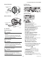
(3) Positioning the Flowmeter
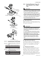
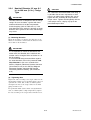
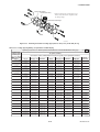
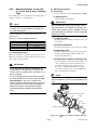
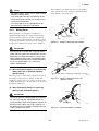
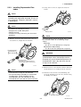
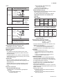
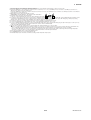
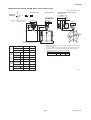
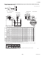
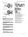
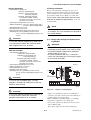
Position the flowmeter so that the Mini-flanges and the
centering devices come in close contact with each
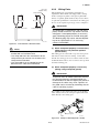
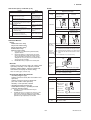
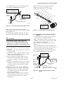
other. Be careful to prevent the four centering devices
from coming into contact with the housing. If stud-type
through-bolts are used, position them in such a way
that the four centering devices come in contact with the
bolt threads (refer to Figure 3.3.4). Pass the other
through-bolts through from the process piping side.
IMPORTANT
Use bolts and nuts in compliance with the flange
ratings. When stud-type through-bolts are used,
be sure the outside diameter of the shank is
smaller than that of the thread ridge. Be sure to
choose a gasket with inner and outer diameters
that does not protrude inside the piping (refer to
Table 3.3.16). If the inner diameter of the gasket
is too large, or outer diameter of the gasket is
too small, fluid leakage may result.
NOTE
Precautions for size 125 mm (5 in.), 150 mm
(6 in.), replaceable electrode type
When installing this type of flowmeter with JIS
F12 (JIS 75M) flanges, turn the flowmeter
slightly because the cover of the electrode
chambers will interfere with the bolts.
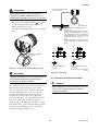
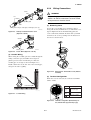
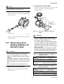
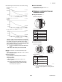
(1) Mounting Direction
Mount the flowmeter so that the flow direction of the
fluid to be measured is in line with the direction of the
arrow mark on the flowmeter.
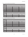
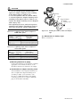
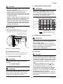
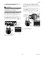
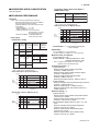
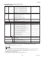
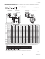
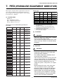
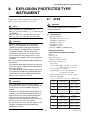
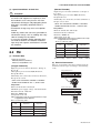
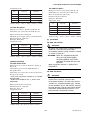
(4) Tightening Nuts
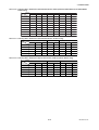
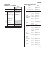
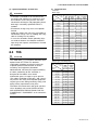
Tighten the nuts according to the torque values for
metal piping in Table 3.3.7. For PVC piping, select an
optional code of GA, GC, or GD, use rubber gaskets
and tighten the nuts to the torque values for PVC
piping in Table 3.3.8.
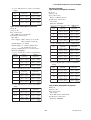
For permeable fluids (such as nitric acid, hydrofluoric
acid, or sodium hydrate at high temperatures), tighten
the nuts according to the torque values in Table 3.3.9.
IMPORTANT
If it is impossible to match the direction of the
arrow mark, the direction of the electrical connection can be changed. Refer to Section 5.1 to
do this properly.
In case the fluid being measured flows against
the arrow direction, refer to the parameter J20:
Flow Direction in the user’s manual of the
AXFA11 Magnetic Flowmeter Remote Converter
(IM 01E20C01-01E) or the AXFA14 Magnetic
Flowmeter Remote Converter/AXF Integral
Flowmeter [Software Edition] (IM 01E20C0201E).
CAUTION
For a flowmeter with fluorocarbon PFA lining, it
is possible that the nuts may loosen as time
passes, so tighten them regularly. Be sure to
tighten the nuts according to the prescribed
torque values. Tighten them diagonally with the
same torque values, step by step up to the
prescribed torque value.
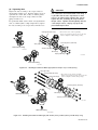
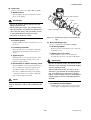
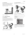
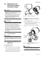
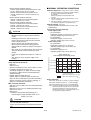
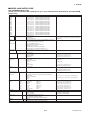
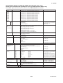
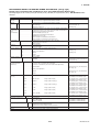
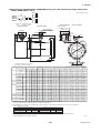
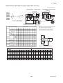
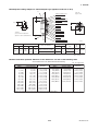
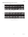
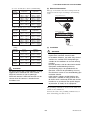
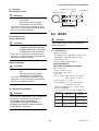
(2) Mounting Centering Devices
To maintain concentricity of the flowmeter with the
pipes, install centering devices. From the process
piping side, pass two through-bolts through the four
centering devices (two for each bolt) and the adjacent
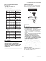
two holes (the lower two holes for horizontal mounting) of both of the flanges (refer to Figure 3.3.4). Use
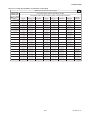
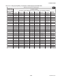
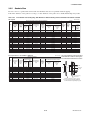
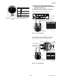
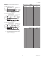
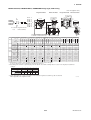
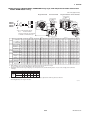
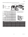
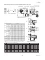
the appropriate centering devices according to the
nominal diameter and the flange ratings. The centering
devices are engraved with an identifying character. Use
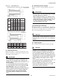
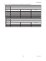
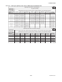
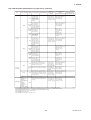
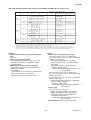
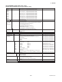
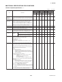
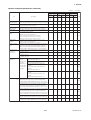
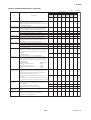
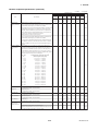
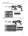
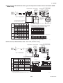
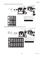
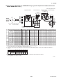
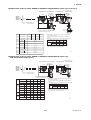
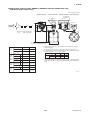
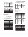
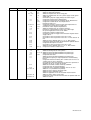
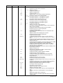
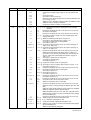
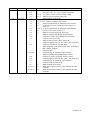
the appropriate ones which meet the required specifications by referring to Table 3.3.10 and Table 3.3.11
(AXF standard models) and Table 3.3.12 (replacement
models for the earlier ADMAG or ADMAG AE).
3-10
IM 01E20D01-01E