1
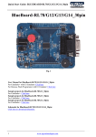
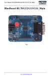
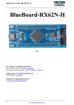
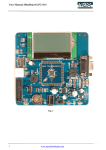
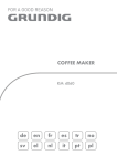
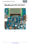
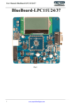
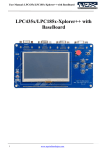
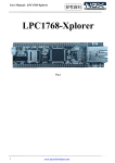
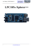
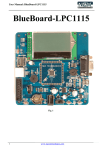
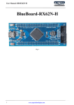
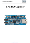
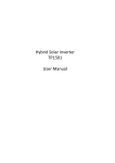
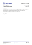
Quick Start Guide: BLUEBOARD-RL78/G13/G14_64pin BlueBoard-RL78/G13/G14_64pin Fig. 1 User Manual for BlueBoard-RL78/G13/G14_64pin: For CubeSuite+ with E1 Emulator: Click here For Renesas Flash Programmer with E1 Emulator: Click here Sample projects for BlueBoard-RL78/G13_64pin: For CubeSuite+: Click here Sample projects for BlueBoard-RL78/G14_64pin: For CubeSuite+: Click here Schematic for BlueBoard-RL78/G13/G14_64pin: Click here to download Schematic. 1 www.ngxtechnologies.com Quick Start Guide: BLUEBOARD-RL78/G13/G14_64pin About NGX Technologies NGX Technologies is a leader in embedded microcontroller product development. We supply reference designs and evaluation modules to silicon companies. Our customers include industry leaders like NXP and RENESAS. Our core business is in helping our customers realize their embedded products. Contact Information: NGX Technologies Pvt. Ltd. No.216, 5th main Road, R.P.C. Layout, Vijayanagar 2nd Stage, Bangalore – 560 104 Phone : +91-80-40925507 email:[email protected] 2 www.ngxtechnologies.com Quick Start Guide: BLUEBOARD-RL78/G13/G14_64pin Table of Contents 1.0 INTRODUCTION ............................................................................................................................ 4 1.1 Possible Debuggers and IDEs that can be used ................................................................................. 4 2.0 BLUEBOARD-RL78/G13/G14_64pin OVERVIEW ........................................................................... 5 2.1 INTRODUCTION ............................................................................................................................. 5 2.2 Board Features ................................................................................................................................... 5 2.3 Block Diagram .................................................................................................................................. 6 2.4 MCU Features ................................................................................................................................... 6 3.0 BLUEBOARD-RL78/G13/G14_64pin Hardware Description............................................................. 8 3.1 Introduction ....................................................................................................................................... 8 3.2 Board Image with pointer to each peripheral & connectors .............................................................. 8 4.0 BLUEBOARD-RL78/G13/G14_64pin hardware verification .............................................................. 9 4.1 Board connections ............................................................................................................................. 9 4.2 Powering the Board ......................................................................................................................... 10 4.3 Verifying all the peripherals of the board ....................................................................................... 10 4.3.1 LED .............................................................................................................................................. 10 4.3.2 BUZZER ...................................................................................................................................... 10 4.3.3 User Switch .................................................................................................................................. 10 4.3.4 Character LCD ............................................................................................................................. 10 4.3.5 RTC .............................................................................................................................................. 11 4.3.6 ADC.............................................................................................................................................. 11 4.3.7 UART1 & UART2 ....................................................................................................................... 11 4.3.8 Supply Voltage Adjustment Pot ................................................................................................... 12 5.0 CHANGE HISTORY .......................................................................................................................... 13 5.1 Change History ................................................................................................................................ 13 6.0 REFERENCES .................................................................................................................................... 13 3 www.ngxtechnologies.com Quick Start Guide: BLUEBOARD-RL78/G13/G14_64pin 1.0 INTRODUCTION This document is the Quick Start Guide for the BLUEBOARD-RL78/G13/G14_64pin, a low cost RENESAS’s RL78/G13/G14_64pin based board by NGX Technologies. This document reflects its contents which include MCU features, hardware description, and hardware verification. This document provides detailed information on board features and hardware verification and possible debuggers and IDEs that can be used with this board. . 1.1 Possible Debuggers and IDEs that can be used E1 Emulator with CubeSuite+ 1.2 E1 Emulator and CuibeSuite+ Board has 14 pin emulator connector, connect the one end of 14 pin cable to E1 emulator and other end to the 14 pin connector on the board, connect usb cable to E1 emulator and PC and connect the power supply to the board as shown in the below image Note: E1 Emulator, 14 pin cable and USB cable are not a part of the BB-RL78/G13/G14_64pin board package. Fig. 2 4 www.ngxtechnologies.com Quick Start Guide: BLUEBOARD-RL78/G13/G14_64pin 2.0 BLUEBOARD-RL78/G13/G14_64pin OVERVIEW 2.1 INTRODUCTION The NGX BLUEBOARD-RL78/G13/G14_64pin is a compact and versatile evaluation platform for the RENESAS's RL78/G13/G14_64pin MCU. RENESAS's evaluation platforms are generally tied up to CubeSuite+ and High Performance Workshop compiler/IDE and E1 Emulator. For our development we use E1 Emulator and CubeSuite+ as the debugger and compiler/IDE respectively. The board is supported by extensive sample examples allowing you to focus on the application development. 2.2 Board Features Following are the salient features of the board Dimensions: 110mm X 120mm Two layer PCB (FR-4 material) Power: DC 6.5V with power LED On-board linear regulators generate +3.3V/500mA 14 pin CORTEX debug connector for Emulator connection User Switch and reset switch 12.0000 MHz crystal for MCU Extension headers for all MCU pins Test LED Character LCD Two RS232 connectors 10K pot for ADC Buzzer 5 www.ngxtechnologies.com Quick Start Guide: BLUEBOARD-RL78/G13/G14_64pin 2.3 Block Diagram Fig. 3 2.4 MCU Features 6 Minimum instruction execution time can be changed from high speed (0.03125µs: @ 32 MHz operation with high-speed on-chip oscillator) to ultra low-speed (30.5µs: @ 32.768 kHz operation with subsystem clock) General-purpose register: 8 bits × 32 registers (8 bits × 8 registers × 4 banks) ROM: 64 KB, RAM: RL78/G13 4 KB, RL78/G14 5.5 KB, Data flash memory: 4 KB On-chip high-speed on-chip oscillator Select from (for RL78/G14 only 64 MHz (TYP.), 48 MHz (TYP.)), 32 MHz (TYP.), 24 MHz (TYP.), 16 MHz (TYP.), 12 MHz (TYP.), 8 MHz (TYP.), 4 MHz (TYP.), and 1MHz (TYP.) On-chip single-power-supply flash memory (with prohibition of block erase/writing function) Self-programming (with boot swap function/flash shield window function) On-chip debug function www.ngxtechnologies.com Quick Start Guide: BLUEBOARD-RL78/G13/G14_64pin On-chip power-on-reset (POR) circuit and voltage detector (LVD) On-chip watchdog timer (operable with the dedicated low-speed on-chip oscillator) On-chip multiplier and divider/multiply-accumulator 16 bits × 16 bits = 32 bits (Unsigned or signed) 32 bits ÷ 32 bits = 32 bits (Unsigned) 16 bits × 16 bits + 32 bits = 32 bits (Unsigned or signed) On-chip key interrupt function On-chip clock output/buzzer output controller On-chip BCD adjustment I/O ports: 16 to 120 (N-ch open drain: 0 to 4) Timer • 16-bit timer: 8 to 16 channels • Watchdog timer: 1 channel • Real-time clock: 1 channel (Correction clock output) • Interval timer: 1 channel Serial interface CSI UART/UART (LIN-bus supported) I2C/Simplified I2C communication Different potential interface: Can connect to a 2.5/3 V device when operating at 4.0 V to 5.5 V 8/10-bit resolution A/D converter (VDD = EVDD =1.6 to 5.5 V): 6 to 26 channels Standby function: HALT, STOP, SNOOZE mode Power supply voltage: VDD = 1.6 to 5.5 V Operating ambient temperature: TA = -40 to +85°C For the most updated information on the MCU please refer to RENESAS's website. 7 www.ngxtechnologies.com Quick Start Guide: BLUEBOARD-RL78/G13/G14_64pin 3.0 BLUEBOARD-RL78/G13/G14_64pin Hardware Description 3.1 Introduction The NGX BLUEBOARD-RL78/G13/G14_64pin is based on RL78/G13/G14_64pin microcontroller from RENESAS. RL78/G13/G14_64pin offers 64-KB Flash memory, 32-MHz operation, ADC: Up to 20 channels, 10-bit resolution, 2.1µs conversion time, D/A converter: 2 channels, 8-bit resolution, Onchip temperature sensor and wide range of peripherals. Refer to the RL78/G12/G13/G14 data sheet for complete device details. BLUEBOARD-RL78/G13/G14_64pin microcontroller is factory-programmed with a quick start demo program. The quick start program resides in RL78/G13/G14_64pin on-chip Flash memory and runs each time power is applied, unless the quick start has been replaced with a user program. 3.2 Board Image with pointer to each peripheral & connectors Fig 4 8 www.ngxtechnologies.com Quick Start Guide: BLUEBOARD-RL78/G13/G14_64pin 4.0 BLUEBOARD-RL78/G13/G14_64pin hardware verification NGX's BlueBoard-RL78/G13/G14_64pin board evaluation platforms ship with a factory-programmed test firmware that verifies the board peripherals. It is highly recommended that you verify the board, before you start programming. Also this exercise helps you get acclimatized with the board quickly. To run the tests you will need the following: BLUEBOARD-RL78/G13/G14_64pin Power: DC 6.5V Supply PC Serial RS232 cable 4.1 Board connections BlueBoard Peripheral Schematic labels MCU pins User LED LED 21 Buzzer BUZZER 64 User Switch INTP1 33 Reset Switch NRST 6 Character LCD LCD_D0 LCD_D1 LCD_D2 LCD_D3 LCD_D4 LCD_D5 LCD_D6 LCD_D7 LCD_RS LCD_R/W LCD_EN LED+ ANI2 29 28 27 26 25 24 23 22 17 18 19 20 54 UART1 RXD1 TXD1 59 60 UART2 RXD2 TXD2 TOOL0 NRST 42 43 5 6 Vdd_MCU 15 ADC E1 Emulator Power Supply Table.1 9 www.ngxtechnologies.com Quick Start Guide: BLUEBOARD-RL78/G13/G14_64pin 4.2 Powering the Board The BLUEBOARD-RL78/G13/G14_64pin requires DC supply of 6.5V.1A rating to power it up, alternatively the board could be powered through Emulator. 4.3 Verifying all the peripherals of the board The following section focusses on the verification of all the peripherals supported on the board. The order of the tests is mentioned in the same manners as the flow of the test firmware. We highly recommend that you follow the order of the test. The test firmware is designed in a manner that the user needs to spend as minimum time as possible to verify all the peripherals. Note: It is highly recommended that the user tests all the peripherals as soon as the board is received. Power up the board and we are all set to verify the board peripherals. The order of the peripherals that are verified by the firmware are as follows: 4.3.1 LED Test setup and verification: As soon as the board is turned ON or reset; the test LED (D1) go ON & OFF for a couple of times, this simple test validates the LED. 4.3.2 BUZZER Test setup and verification: When the board is turned ON or reset you will hear a beep after few seconds. This confirms the status of the Buzzer. 4.3.3 User Switch Test setup and verification: When you press the User Switch, LED (D1) toggles. 4.3.4 Character LCD Test setup and verification: A message “WELCOME TO NGX TECHNOLOGIES” should be displayed on the Character LCD. 10 www.ngxtechnologies.com Quick Start Guide: BLUEBOARD-RL78/G13/G14_64pin 4.3.5 RTC Test setup and verification: Next, the firmware validates the internal RTC. The RTC value is read and displayed on the character LCD. 4.3.6 ADC Test setup and verification: The ADC pin is connected to a potentiometer. To test the ADC rotate the wheel of the potentiometer, as The position varies the ADC value sensed is displayed on the LCD display. Note: Since the RL78G13/G14 has a 10-bit ADC, the values of the ADC reading will range from 0x0000 to 0x1023. 4.3.7 UART1 & UART2 Note: The UART1 and UART2 test is not there in the factory-programmed test firmware , user need to load the UART1 and UART2 sample firmware separately then follow the below steps. To load the firmware follows the steps in section 3.2 in the user manual. Test setup and verification: Open the hyper terminal as shown in the below image. To test the UART1& UART 2 open the hyper terminal with settings 9600bps 8N1, i.e. Baud Rate: 9600 bps Bits: 8 Parity: None Stop bits: 1 Flow Control: None Fig 5 11 www.ngxtechnologies.com Quick Start Guide: BLUEBOARD-RL78/G13/G14_64pin A ‘Connect To’ window opens where you have to select the COM port. In this example it is COM26.Click OK. A ‘COM26 Properties’ window appears. Set the values as shown below. Click OK. Note: Please check for your machines COM port number. The COM port number can be different. Fig 6 Fig 7 Next a ‘Hyper Terminal’ window opens as shown. Fig 8 4.3.8 Supply Voltage Adjustment Pot Test setup and verification: This pot demonstrates the MCU can work for variable voltages i.e 1.6 V to 5.5 V. We have verified user LED (D1) blinky at voltage 1.8V. Adjust the pot to set the voltage between the specified ranges and test the user LED (D1) blinky, LED (D1) should toggle. 12 www.ngxtechnologies.com Quick Start Guide: BLUEBOARD-RL78/G13/G14_64pin 5.0 CHANGE HISTORY 5.1 Change History Rev 1.0 Changes Date (dd/mm/yy) Initial release of the Quick 28/05/2012 Start Guide By Veeresh Tumbaragi 6.0 REFERENCES In addition to this document, the following references are included on the NGX BLUEBOARDRL78/G13/G14_64pin product and can also be downloaded from www.ngxtechnologies.com: NGX BLUEBOARD-RL78/G13/G14_64pin schematic for the Development board. Additional references include: Information on development tool being used: - CubeSuite+, http://sg.renesas.com/products/tools/ide/ide_cubesuite_plus/ About this document: Revision History Version: V1.0 author: Veeresh Tumbaragi Company Terms & Conditions Legal NGX Technologies Pvt. Ltd. provides the enclosed product(s) under the following conditions: This evaluation board/kit is intended for use for ENGINEERING DEVELOPMENT, DEMONSTRATION, and EDUCATION OR EVALUATION PURPOSES ONLY and is not considered by NGX Technologies Pvt. Ltd to be a finished end-product fit for general consumer use. Persons handling the product(s) must have electronics training and observe good engineering practice standards. As such, the goods being provided are not intended to be complete in terms of required design-, marketing-, and/or manufacturing-related protective considerations, including product safety and environmental measures typically found in end products that incorporate such semiconductor components or circuit boards. This evaluation board/kit does not fall within the scope of the European Union directives regarding electromagnetic compatibility, restricted substances (RoHS), recycling (WEEE), FCC, CE or UL and therefore may not meet the technical requirements of these directives or other related directives. The user assumes all responsibility and liability for proper and safe handling of the goods. Further, the user indemnifies NGX Technologies from all claims arising from the handling or use of the goods. Due to the open construction of the product, it is the user’s responsibility to take any and all appropriate precautions with regard to electrostatic discharge. 13 www.ngxtechnologies.com Quick Start Guide: BLUEBOARD-RL78/G13/G14_64pin EXCEPT TO THE EXTENT OF THE INDEMNITY SET FORTH ABOVE, NEITHER PARTY SHALL BE LIABLE TO THE OTHER FOR ANY INDIRECT, SPECIAL, INCIDENTAL, OR CONSEQUENTIAL DAMAGES. NGX Technologies currently deals with a variety of customers for products, and therefore our arrangement with the user is not exclusive. NGX Technologies assumes no liability for applications assistance, customer product design, software performance, or infringement of patents or services described herein. Please read the User’s Guide and, specifically, the Warnings and Restrictions notice in the User’s Guide prior to handling the product. This notice contains important safety information about temperatures and voltages. No license is granted under any patent right or other intellectual property right of NGX Technologies covering or relating to any machine, process, or combination in which such NGX Technologies products or services might be or are used. Disclaimers Information in this document is believed to be reliable and accurate. However, NGX Technologies does not give any representations or warranties, expressed or implied, as to the completeness or accuracy of such information and shall have no liability for the consequences of use of such information. NGX Technologies reserves the right to make changes to information published in this document, at any time and without notice, including without limitation specifications and product descriptions. This document replaces and supersedes all information supplied prior to the publication hereof. Trademarks All referenced trademarks, product names, brands and service names are the property of their respective owners. 14 www.ngxtechnologies.com