1
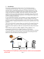
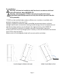
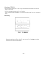
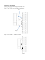
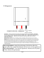
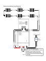
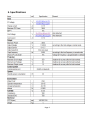
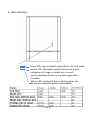
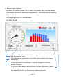
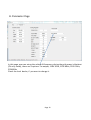
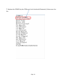
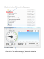
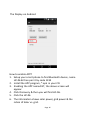
Hybrid Solar Inverter
TP1501
User Manual
IMPORTANT SAFETY INSTRUCTIONS
SAVE THESE INSTRUCTIONS
To reduce the risk of electrical shock and to ensure safe installation and operation
of Hybrid Solar Inverter, please carefully read and strictly follow all safety
instructions and cautionary markings.
CAUTION — Risk of Electric Shock – Plates are live. Disconnect before servicing.
CAUTION — Risk of Electric Shock , Do NOT Remove Cover. No User Serviceable
Parts Inside. Refer Servicing To Qualified Service Personnel.
WARNING — For Continued Protection Against Risk Of Fire, Connect the Grid
INPUT(2 black wires) with 20A circuit breaker or fuse.
CAUTION — To reduce the risk of electric shock and fire – Do not connect the
Hybrid OUTPUT(2 red wires) to ground.
CAUTION — Be sure the polarity of PV wires. The RED wire is connected to the
positive polarity of the PV string. The BLACK wire is connected to the negative
polarity of the PV string. The mistake may cause the damage or fire.
CAUTION — To reduce the risk of electrical shock, disconnect both AC and DC
power from the Hybrid Inverter before attempting any maintenance or cleaning
or working on any circuits connected to the inverter.
Turning off controls will not reduce this risk. Internal capacitors remain charged
for 5 minutes after disconnecting all sources of power.
WARNING — All electrical installation shall be done in accordance with local and
national codes ANSI/NFPA 70.
WARNING — Connecting this unit to the electrical grid shall only be performed by
qualified personnel and only after formal approval from the utility company.
WARNING — This device contains no user serviceable parts inside. Please return
the unit to authorized Service Center for maintenance.
CAUTION — This unit should be mounted on firm background and under a
shading roof to avoid exposure to direct sunlight and rain.
CAUTION — Rear heat sink of this unit may exceed 80 °C (175°° F ). Don’t touch to
avoid risk of burning.
Page 1
Table of contents
1. Introduction
2. Installation
3. Wiring process
4. Operating procedure
5. Specifications
6. LED indication
7. Monitoring system
8. Trouble shooting
Page 2
1. Introduction
The system is a Hybrid photovoltaic inverter. The 2 hybrid sources are
Photovoltaic(PV) & Grid power. There is no expensive and bulky batteries
required. Hence, eliminating large expenses on battery maintenance. It can
convert Photovoltaic DC energy via solar panel modules and invert collected
energy into alternate current(AC), which then output to the certain home
appliances that are proudly powered by solar, renewable energy. Once the PV
energy is not good enough for the appliances, the Grid power will support the
rest of the energy automatically.
In case of the electric blackout, the Grid power is no longer supporting the rest
energy once the PV energy become weak. The power support to the home
appliances need to be reduced dependent on the # of the PV panel installed &
the sun condition. Unplug some appliances to keep some important ones in this
condition.
This is not a Grid-tied PV inverter. There is no risk of the PV energy fed into the
grid power. Hence, it is sure the TP1501 make the PV panels on the rooftop
energize the home appliances under the roof possible with safety & the lowest
cost.
The TP1501 can operate for 110Vac, 50/60Hz, 220Vac, 50/60Hz, It can
automatically synchronize the voltage & frequency of Grid Power.
The TP1501 Hybrid PV inverter system can be monitored remotely via software.
It provides users with convenient power monitoring and recording functions
without the need of additional monitoring systems.
AC
disconnect
DC BOX
AC plug for Aircon,
Refrig, TV and LED
* The traditional Air Conditioner without Inverter inside is not recommended
as the Load
Page 3
2. Installation
Warning : All electrical installation shall be done in accordance with local
codes and national odes ANSI/NFPA 70.
Warning : Connecting the TP1501 to the electrical grid shall only be
performed by qualified personnel and only after formal approval from the
utility company.
TP1501 can be installed indoor where sufficient air circulation is available with
ambient temperature less then 50℃.
Outdoor installation should be under controlled environment where no direct
sunlight would reach, as excessive heating would damage internal components and
should minimize exposure to rain despite her high protection class NEMA 3R.
The unit should be installed in a location normally inaccessible to persons.
Please install this unit at eye-height (over 1 meter), so that all information and status
from LED can be read easily.
Mount only on firm background and with correct position as below :
Page 4
Mounting of TP1501
Place the metal fixing plate on the designated surface of the wall and mark the
holes of the screw.
Drill the holes and hammer in the wall anchors.
Place the metal fixing plate again and fasten the eight screws into their respective
holes.
Metal fixing
Metal fixing plate
Mount the unit on the fixing plate. Be sure that the four hooks get into their
respective fixtures and settle down
Page 5
Placement of TP1501
Step1 : The screws will bracket fixed to the wall.
Step2 : The TP1501 are installed on the bracket.
Step 2
Step 1
Step3 : The TP1501 is fixed on the wall
Page 6
3. Wiring process
PV
OUTPUT
GRID
60-150Vdc for 110Vac output 1500W@110Vac 90-125 AC 50/60Hz
60-300Vdc for 220Vac output 3000W@220Vac
OR
190-245 AC 50/60Hz
WARNING —Follow local electrical codes and the National Electrical Code (NEC), ANSI/NFPA
70. Use copper conductors only with minimum 12AWG , 105℃ , 600V wire for power grid and
minimum 12AWG , 105℃ ,600V wire for solar panel connections with the PV-Inverter.
Power cable selection:
AC wire: Black copper wires of 12 AWG or above should be used for alternate current input.
Output wire: Red copper wires of 12 AWG or above should be used for alternate current output.
DC wire: For PV input from solar panels, the cross section area is dependent on the length of the
wire. Identifiable colored copper wires of 11 AWG(section size 4.0mm2) or above. Connect the
most positive point from the panels to the red wire of the PV input of TP1501 & the most
negative point to the black wire of the PV input of TP1501. NEC 2008 / UL 4703 approval PV wire
is recommended.
Turn on procedure : Apply the grid power first & then after the
green LED active, apply the PV power. & then turn on the appliances
Turn off procedure : Turn off the appliances. Remove the PV power
& then remove the grid power.
Page 7
Recommended wiring Diagram
PV Panels
DC BOX
Extension wire(4)
Hybrid
Inverter
TP1501
110/220 50/60Hz
20A
Breaker
AC Plug
Page 8
Note : The AC wiring concept ;
Disconnect the wire between the circuit
breaker & load. & then connect the
circuit breaker to the Grid input of the
TP1501 & connect the load to the output
of TP1501
5. Specifications
Page 9
6. LEDs indication
Green LED : light in Hybrid mode, Blink in PV only mode
Amber LED : light when system failed such as grid
voltage out of range or output over current,
system shutdown & will try to restart again after
1 minute.
Yellow LED : display PV status, blinking when the
PV panel’s maximum power point tracked
Page 10
7. Monitoring system
There are 2 monitor system for TP1501, one run on Microsoft Windows,
XP or above version for Personal Computer(PC) , the other run on Android
for smart phone.
The display of the PC is as below :
A. Main Page
1. Solar vs. Grid ratio: display the percentage of the power from solar &
grid for supplying load
2. Display the real-time power of the solar & grid supply to the load by
wattage(W)
3. The local electricity cost $/KWH, User can change this value by
double clicking it.
4. Link the history data to Microsoft Excel or Open Office Excel. Double
click the button to enable it.
5. Energy(WH) of solar vs. Grid by hour. Updated everyday.
Page 11
B. Parameter Page
In this page, user can setup the voltage & frequency during the grid power is blackout
(PV only mode), there are 5 options : no output, 110V 50Hz, 110V 60Hz, 220V 50Hz,
220V60Hz
Check the local dealer, if you want to change it.
Page 12
C. How to enable the Bluetooth communication
1.
2.
3.
4.
5.
Click the right button while point to the Bluetooth icon in your PC.
Select the Add device option.
Computer will find the new Bluetooth device named HC-06
Pair HC06 with your computer by code 1234
After the Bluetooth successfully installed. Right click the HC-06 & then
select the property & select the “Hardware” to find which COM port that
linked with HC-06. For example COM10 or COM 27.
6. Open the setting.INI file of the Monitoring fold in the CD enclosed with the
TP1501 package
Page 13
7. Replace the COM26 by the COM port that linked with Bluetooth, & then save the
file
Page 14
8. Double click the Aircon.COM to enable the Display program
9. There will be “The com port open success” shown on the bottom line
Page 15
The Display on Android
How to enable APP?
1. Setup your smart phone to find Bluetooth device, name
HC-06 & then pair it by code 1234
2. Install the APP program, *.apk in your CD.
3. Enabling the APP named BT, the above screen will
appear.
4. Click Discovery & then you will find HC-06.
5. Click the HC-06
6. The information shows solar power, grid power & the
ration of Solar vs. grid.
Page 16
Trouble shooting :
1. No LED active & no output
.
It may take about 30 seconds for the system initialized every
time when the grid power first applied. After that, the green
LED will be active. If the green LED doesn’t light. Check the
connection of the grid power.
2. No output & the middle amber LED active :
a. Disconnect the output load to check if the amber LED off
after one minute.
b. Check if the input voltage is not in the range 90V~125V,
190V~242V.
3. Solar doesn’t generate power( yellow LED not active in the day
time):
In the day time, if the bottom yellow LED blinking, which means
the solar is generating the power. If the yellow LED is not active
in the day time, please check the connection of the PV panels.
Page 17