1
SDR Platform for Wireless Cooperative Protocols Master thesis by Jakob Sloth Nielsen and Bjarke Freund-Hansen Fall 2009 & Spring 2010 Elite 10 Gr. 1011 Department of Electronic Systems 9th and 10th semester Fredrik Bajers Vej 7 Telephone 96 35 86 90 http://es.aau.dk Abstract: Title: SDR Platform for Wireless Cooperative Protocols Subject: Wireless Communication Project period: Fall 2009 & Spring 2010 Project group: 10gr1011 Group members: Bjarke Freund-Hansen Jakob Sloth Nielsen Supervisors: Associate Professor Petar Popovski Professor Torben Larsen Publications: 5 Pages: 88 Finished: 3rd of June, 2010 This project concerns the development of a platform for rapid prototyping and evaluating of wireless cooperative protocols under real-world conditions. The platform is built using a heterogeneous hardware basis, consisting of mobile embedded devices and the GNU Radio SDR toolkit using the USRP2. It operates in the 2.4GHz ISM band and a default implementation based on the Bluetooth radio and baseband layer is developed. The platform is modelled on a two-way relay scenario, consisting of a single relay node facilitating communication between two endpoint nodes. To demonstrate the possible application of the developed platform, an experiment comparing the achievable throughput for relaying without network coding and with XOR network coding is performed. The results shows the platform is applicable for comparison and evaluation of an implementation of Bluetooth relaying, with and without XOR network coding. From the results it is concluded that the platform may serve as the basis for further research in wireless cooperative protocols. PREFACE This report is written as the master thesis project by Jakob Sloth Nielsen and Bjarke Freund-Hansen at Aalborg University in the fall of 2009 and spring of 2010. The project concerns the development of a platform for implementation of wireless cooperative protocols, and performing experiments on this implementation. In this report we investigate the benefits of wireless cooperative protocols, and determines the requirements for a platform allowing implementation of these. To support high flexibility a heterogeneous hardware basis for the platform, based on mobile embedded devices and a software defined radio (SDR) solution, is chosen. The primary contribution of this project is the development of the platform. This necessitates the integration of communication between the embedded platform, and the SDR solution based on GNU Radio. Which again involves adapting the GNU Radio toolkit to perform packet-based radio, and developing the necessary physical and data-link layer implementation, based on Bluetooth. This report is written to document the effort in developing the platform, with the intention of serving as a user manual and design document, for further developers extending the platform, or implementing experiments on top of the platform. Chapter 1 explains the background for the project, discusses the necessity of the platform, and concludes by defining the scope of the project. Chapter 2 is a summary of the lower layers of the Bluetooth protocol, the baseband and radio layers, along with a discussion of the requirements stipulated on the design. It concludes with an example of applying a cooperative technique, network coding, to Bluetooth. Chapter 3 documents the design of the different parts of the platform. The challenges are discussed and the solutions to the challenges are documented. In Chapter 4 the implementation specifics of the platform is discussed. This may be used as a reference for getting started on developing for the platform. Additionally some deviations from the design are described, based on limitations encountered during implementation, and their impact on the platform. Chapter 5 documents an example experiments with Bluetooth relaying, with and without XOR network coding, showing 5 some of the possible uses of the platform, along with examples of the data that may be collected from the platform. Last Chapter 6 concludes on the project, and discusses further steps for improving the platform and for overcoming some of the limitations described in Chapter 4. We would like to thank our thesis supervisors for their support during the many obstacles we faced in this project. Also a thanks to Texas Instruments, and in particular to Thomas Almholt for providing us with the embedded platform used in this project. Finally a thanks to the other project groups on Wireless Communication and Networks and Distributed Systems is appropriate, as intergroup collaboration has as always been a great support during the project. The source code for the software developed throughout this project is available for download at http://kom.aau.dk/group/10gr1011/ and on the enclosed CD. 6 CONTENTS Contents 7 1 Introduction 1.1 Wireless Cooperative Protocols . . . . . . . . . . . . . . . . . . . . . . . 1.2 Evaluation Platform . . . . . . . . . . . . . . . . . . . . . . . . . . . . . 1.3 Project Scope . . . . . . . . . . . . . . . . . . . . . . . . . . . . . . . . . 9 11 14 17 2 Bluetooth 19 2.1 Bluetooth Radio and Baseband Layer . . . . . . . . . . . . . . . . . . . 20 2.2 Bluetooth and Network Coding . . . . . . . . . . . . . . . . . . . . . . . 24 2.3 Summary . . . . . . . . . . . . . . . . . . . . . . . . . . . . . . . . . . . 25 3 Platform Design 3.1 Endpoint . . . . . 3.2 Relay . . . . . . . 3.3 Endpoint Statistics 3.4 Summary . . . . . . . . . . . . . . . . . Collector . . . . . . . . . . . . . . . . . . . . . . . . . . . . . . . . . . . . . . . . . . . . . . . . . . . . . . . . . . . . . . . . . . . . . . . . . . . . . . . . . . . . . . . . . . . . . . . . . . . . . . 26 27 39 48 49 4 Implementation Manual 51 4.1 MSP-EXP430F5438 with CC2500-EM . . . . . . . . . . . . . . . . . . . 51 4.2 USRP2 and GNU Radio . . . . . . . . . . . . . . . . . . . . . . . . . . . 57 4.3 Summary . . . . . . . . . . . . . . . . . . . . . . . . . . . . . . . . . . . 60 5 Relay Experiment 5.1 Experiment Setup . . 5.2 Performance Analysis 5.3 Results . . . . . . . . . 5.4 Summary . . . . . . . . . . . . . . . . . . . . . . . . . . . . . . . . . . . . . . . . . . . . . . . . . . . . . . . . . . . . . . . . . . . . . . . . . . . . . . . . . . . . . . . . . . . . . . . . . . . . . . . . . . . . . . . . . . . . . . . 61 61 63 65 68 6 Conclusion 70 6.1 Discussion . . . . . . . . . . . . . . . . . . . . . . . . . . . . . . . . . . . 71 7 CONTENTS Appendix 74 A GFSK Modulation and Demodulation 74 A.1 GFSK Demodulation . . . . . . . . . . . . . . . . . . . . . . . . . . . . . 75 A.2 GFSK Modulation . . . . . . . . . . . . . . . . . . . . . . . . . . . . . . 77 B GNU Radio Blocks 78 B.1 Custom Blocks . . . . . . . . . . . . . . . . . . . . . . . . . . . . . . . . 79 C Relay Experiment Design 82 C.1 Without Network Coding . . . . . . . . . . . . . . . . . . . . . . . . . . 82 C.2 With XOR Network Coding . . . . . . . . . . . . . . . . . . . . . . . . . 83 D GNU Radio Companion Block 85 Bibliography 86 8 CHAPTER 1 INTRODUCTION Wireless sensor networks (WSN) consists of spatially distributed sensors, that form ad-hoc networks to cooperatively monitor physical conditions and to relay these measurements. The definition of WSN is however ambiguous, as sensor networks in the recent past has found their way into broad and varying applications. Therefore any application of WSN must consider the design space of WSN, defining parameters such as available energy, heterogeneity, communication infrastructure and network topology. [20]. Depending on the lifetime of a sensor node the power may be provided by a battery or harvested from the environment by solar cells, kinetic energy, wave energy, etc., or a combination thereof. Common for all applications is the fact that sensors are naturally resource-constrained, and conservation of power is a must. Likewise the communication infrastructure formed by the sensor network must be considered, defining parameters such as heterogeneity. Does the network consists of entirely homogeneous sensors, all acting on an equal basis with regard to sensing the environment and participating in the network? Or does the sensors constitute a more heterogeneous network, where sensor nodes carry a different range of environmental sensors and contribute differently to the network? This project consider heterogeneous WSN where nodes contributes to the network with varying capabilities and resource availability. A sensor network where sensor nodes have varying energy availability naturally have a preference towards a non-homogeneous network structure. Where nodes with high energy availability (and perhaps lower environment sensing responsibilities) contribute more to formation of the network infrastructure than nodes with less available energy. This may even be the case for entirely homogeneous WSN where e.g. deployment is random and energy is harvested from the environment by equipping sensors with solar cells. In this case some sensors will be exposed to sunlight more than other sensors, 9 CHAPTER 1. INTRODUCTION and thus would be favorable for bearing the responsibility of carrying the bulk load of information in a wireless network backbone infrastructure. Where lesser nodes are then only required to relay their measurements to the nearest backbone node. Relay Endpoint Figure 1.1: Network infrastructure of a two-class wireless sensor network. Thus in many applications of WSN, sensor nodes participate in the sensor network differently. In this project the special case with two separate classes of nodes is considered. The first class consists of sensor nodes with limited power availability, and the second class consists of sensor nodes with a less restricted power budget. The second class, called relay nodes, constitute the wireless backbone of the sensor network. Figure 1.1 illustrates the possible topology of such a two-class network. In addition this project includes both sensors and actuators, and nodes containing a mixture of both, in the definition of the first class, which are called endpoint nodes. Therefore endpoint nodes act as both sources and sinks of data, where relay nodes perform relaying of data between endpoints nodes and other relay nodes. These two classes naturally have different roles in the infrastructure of the network. The relay nodes becomes the bottlenecks of the network, this is discussed further in Section 1.1.1. To accommodate this network structure and network bottlenecks, application of wireless cooperative protocols is an option. Application of cooperative protocols to the ad-hoc network formed by WSN may increase the communication rate across the network and/or increase the communication reliability. [11] Thus the initial problem of this project is defined as: How may wireless cooperative protocols be applied in wireless sensor networks to support the different requirements of these two classes of sensor nodes, and how may the contribution to the network of the applied cooperative protocol be evaluated? In order to investigate this problem, the rest of this chapter concerns an analysis of wireless cooperative protocols and an analysis of the requirements for an evaluation platform, that allows evaluation of the contribution provided by these cooperative 10 1.1. WIRELESS COOPERATIVE PROTOCOLS protocols. In the end of this chapter the scope of this project is defined based on this initiating problem. 1.1 Wireless Cooperative Protocols Cooperative communication in wireless networks exploit some of the features of the wireless medium to optimise communication within the network, either by increasing the overall throughput in the network, or by increasing reliability [11]. Path 2 Path 2 Path 1 Figure 1.2: Cooperative communication using multipath routing. One of the important features of a wireless network is that the medium is shared and that all transmissions are inherently broadcasted. This feature is exploited for cooperative communication as illustrated in Figure 1.2. Here the red node transmits a message to the green node using path 1. This transmission is overheard by the blue node, who forwards the overheard transmission to the green node using path 2. The green node now has received the same data using two paths, or channels, which it may use to achieve a greater reliability of the received data [14]. In a network based on relaying, as described in the previous section, the cooperate technique of network coding may increase the throughput across the network. This technique is elaborated upon in the following section. 1.1.1 Network Coding In conventional network routing, a node receives a packet, checks the destination of the packet, and forwards the packet through the correct channel. In this type of routing problems may occur, if many packets have to be routed through a single node, e.g. a relay node. This node becomes a bottleneck in the network, an example of this is illustrated in Figure 1.3. Figure 1.3a depicts two clusters of interconnected nodes. The clusters are connected to each other through a single link between two nodes, which forms the bottleneck nodes. Figure 1.3b is an example of a simple relay scenario with two endpoint nodes and a relay node that interconnects the two endpoint nodes. The relay node is a bottleneck in the network. In order to improve the throughput at the relay nodes of a network, network coding may be used. An example of network coding may be seen in Figure 1.4, where two nodes (Alice and Bob) communicates through a relay node. With conventional routing, 11 CHAPTER 1. INTRODUCTION Bottleneck Nodes (a) A network bottleneck. Bottleneck Node (b) Network bottleneck in a relay scenario. Figure 1.3: Bottlenecks in a network. Figure 1.4b, Alice first transmits a packet to the relay node, which relay the packet to Bob. Next Bob transmits a packet to the relay node, which again relay the packet, this time to Alice. This is a total of 4 transmissions in order for Alice and Bob to exchange packets. Using network coding, Figure 1.4c, this is reduced to three transmissions, since the relay node waits until it has received a packet from both Alice and Bob, then it codes the two packets to one and broadcast it, so both Alice and Bob receives it. Alice and Bob are both able to decode the packet using their own original packet. In this example there is a coding gain of 43 , because 4 transmissions are reduced to 3 using network coding. A challenge with network coding in the relay scenario is; if Alice wish to transmit a packet to Bob, and Bob does not desire to transmit anything to Alice. How long shall the relay node wait for a packet from Bob to code the packet from Alice with, before it relays Alice’s packet with no network coding. If it delays transmission for too long it introduces a delay in the system, possibly lowering the overall throughput through the relay. There are multiple types of digital network coding, XOR, Linear Coding, Random Network Coding, etc. [29]. This project mainly concerns binary XOR network coding, which is XOR’ing of the binary data. In the example in Figure 1.4c, this would mean, that the relay node makes a binary XOR of the packets from Alice and Bob, which is then broadcasted. Upon reception Alice and Bob performs an XOR of the received coded packet with their original transmitted packets to extract the packet from the other party. Physical Layer Network Coding In conventional network routing it is desired, that each transmission does not interfere with another transmission, since this results in a collision. However in physical layer network coding this interference is embraced, and it is desired, that two given nodes transmit at the exact same time [9]. When two nodes transmit at the same time, the relay node receives an interfered signal. If this interfered signal is just forwarded to the recipients, using a single broadcast, the two nodes may in principle be able to obtain the other parties packet by subtracting their original transmission from the received broadcast. This is called amplify-and-forward [11], and results in a gain of 24 . 12 1.1. WIRELESS COOPERATIVE PROTOCOLS Relay Alice Bob (a) Alice and Bob relay topology. Node Bob Alice Relay Time Slot (b) Conventional Routing. Node Bob Alice Relay Time Slot (c) Digital Network Coding. Figure 1.4: Gain of network coding in a relay scenario. An example of the Alice and Bob scenario using physical layer network coding may be seen in Figure 1.5. Node Bob Alice Relay Time Slot Figure 1.5: Physical layer network coding. 13 CHAPTER 1. INTRODUCTION 1.2 Evaluation Platform Advances in cooperative communication are often demonstrated by mathematical information theoretical analysis. And despite recent progress in this area, there still remain significant barriers to applying these results in development of practical network protocols [11]. Thus for evaluation of the previously described cooperative wireless protocols, the usual approach is to make an implementation in a simulated environment, and perform relevant performance measures showing whether a suggested technique may in reality improve the performance. The simulation is however inherently a limited imitation of the real world, and thus limiting the real world usability of the obtained results to a set of assumptions. One of these assumptions is typically neglecting the overhead, introduced by the necessity of applying signalling strategies, required to accommodate the variation in the communication channel of wireless networks. This signalling overhead becomes a recurring cost, which may be rather significant. [11] The next step in the process is to perform an implementation on actual hardware, and test the technique in real-world scenarios under realistic conditions. This process is often both very time-consuming and expensive. The availability of cheap software defined radio (SDR) platforms and RF evaluations boards is however changing this, and providing a more feasible alternative or supplement to simulation. This project aims to develop a platform for evaluation of wireless techniques in real environments. This platform is based on a two-way relay scenario, described in the next section. It is chosen to base the platform on the Bluetooth baseband and radio layers. First because it is a protocol with an open specification, maintained by the Bluetooth Special Interest Group, and second because Bluetooth controller devices are cheap and readily available for use in sensor networks. Many existing sensors are already based on Bluetooth, and may thus benefit from the application of these wireless techniques. Furthermore the protocol employs a star-topology, and thus lends itself nicely to a relay scenario. The techniques described in the previous section is not limited to Bluetooth, and the developed platform is in itself neither limited to Bluetooth, except that the default implementation is based on Bluetooth. In summary, the aim of this project is to create a platform, where wireless cooperative protocols may be evaluated under real-life conditions, with the necessary signaling included. Thus bridging the gap between a theoretical proposal and the practical requirements for implementing that proposal. The next section describes the two-way relay scenario this platform is based on. 1.2.1 Scenario The scenario is an example of an application where two wireless endpoint nodes communicate using Bluetooth, through a relay device acting as Bluetooth master, thus forming a small star-topology. This is illustrated in Figure 1.6. 14 1.2. EVALUATION PLATFORM Relay Endpoint 1 Endpoint 2 Figure 1.6: Scenario. It is assumed, that the two endpoint devices have access to less power than the relay device, thereby it is desired to conserve power on the endpoint devices, while, if necessary, increase power usage on the relay device. As discussed initially in Chapter 1 the two endpoint devices acts as the sources and sinks of data, while the relay nodes only task is to relay data between the two endpoints. 1.2.2 Hardware In order to implement the platform described in the previous sections, it is necessary to decide on which hardware to base respectively the relay node and the endpoint nodes. This section contains a discussion of the requirements for hardware necessary for implementing the platform. It concludes by choosing a hardware platform and describing the properties of this platform. Hardware Requirements In the relay scenario two types of Bluetooth nodes are required: • A relay node, acting as Bluetooth master. • Two endpoint nodes, acting as Bluetooth slaves. It would appear to be an obvious choice to select existing proprietary Bluetooth devices for the endpoint and the relay node, and build the platform on top of that. The wireless techniques described in Section 1.1, does however reside naturally on the lower protocol layers, primarily on the baseband layer, and for physical network coding on the radio layer as well. Therefore it is desired to provide the ability to build experiments, that requires modification of the lower layers of Bluetooth. For this there are no apparent choices of existing Bluetooth platform, because proprietary Bluetooth devices usually implement the controller stack in hardware (e.g. as an ASIC), cf. Chapter 2. The advantage of hardware implemented baseband and radio layers, and in particular the disadvantage of implementation of the same in software, becomes apparent from the discussion in Chapter 4. Thus the requirements for, and possibilities of, a hardware platform for the endpoint nodes and the relay node, are discussed in the next two sections. 15 CHAPTER 1. INTRODUCTION Endpoint Nodes Bluetooth employs Gaussian Frequency Shift Keying (GFSK) modulation at a basic rate of 1 Mbit/s in the 2.4 GHz ISM spectrum [5]. This forms the basic requirements for the radio part of the endpoint node hardware, it shall be able to: • Transmit and receive in the 2.4 GHz ISM spectrum. • Employ GFSK modulation with a rate of 1 Mbit/s. • Provide raw access to a bit-stream of demodulated symbols, and accept a raw bit-stream for modulation and transmission. Furthermore the devices shall be mobile, for setup and testing in the real environment, where the protocol or technique under test is indented for use. Thus a straightforward solution is to use an embedded platform with a microprocessor unit (MCU) and a radio module. For this project development boards accompanied by RF modules from Texas Instruments (TI) are provided. These development boards are based on the MSP430 MCU architecture, and are of type MSP-EXP430F5438. They each contain, among other things, a MSP430F5438IPZ microcontroller and a CC-EM Header with the possibility of attaching a CC2500EM radio board. The CC2500EM is a RF evaluation module based on the CC2500 IC from TI with embedded driving circuitry and antenna. The CC2500 is a low cost, low power 2.4 GHz RF transceiver designed for low power wireless applications in the 2.4 GHz ISM band. It supports programmable output from −55dBm to 1dBm, with a receiver sensitivity of −83dBm at a data rate of 500kBaud (for a 1% packet error rate with 20 bytes packets). OOK, 2-FSK, GFSK, and MSK modulation types are supported, however only up to a data rate of 250kBaud for the GFSK modulation type. The radio supports several packet-handling features, such as preamble detection, sync word matching, address check, and automatic CRC handling. It does however also support raw access to demodulated symbols, and accepts raw symbols for modulation. [27] These boards supports all our requirements to the endpoint node hardware, except for the limitation of only supporting 1/4 the data rate of the basic Bluetooth rate. It is chosen to base the endpoint nodes on these boards, thus limiting the data rate of the platform to 250kBit/s. Relay Node As described earlier, the relay node acts as a Bluetooth master in the network with the two endpoints as Bluetooth slaves. Following is a analysis on the requirements for the relay node. This is based on the previous description of the platform and cooperative protocols. Implementation of physical layer network coding necessitates access to the raw signal before demodulation on the relay node. Since it is desired to design and implement a platform, that supports implementation of all the methods described in Section 1.1, a 16 1.3. PROJECT SCOPE requirement for the hardware for the relay node is, that it shall supply access to the raw radio signals in order to support building custom modulation schemes. In addition the relay node shall fulfill the requirements to the endpoint node hardware. A Software Defined Radio (SDR) solution is an obvious contender to this task, typically allowing high-speed access to digital In-phase and Quadrature (IQ) samples. A Bluetooth channel has a width of 1 MHz (however with a nominal width of the signal of 2 · f¯d = 315 kHz). Thus the SDR solution is required to be able to perform bandpass sampling of at least 2 MSamples/s in the 2.4 GHz ISM band. Additionally the data rate of Bluetooth of 1 Mbit/s also demands a sampling rate of at least 2 MSamples/s. For practical uses it is often necessary to be able to oversample the signal. Thus it is estimated, that a sample rate of at least 10 MSamples/s is desired, allowing oversampling of at least 10 Samples/bit (1.1). 10 MSamples/s 1 Mbit/s = 10 Samples/bit (1.1) A SDR platform, that comply with these requirements is the Universal Software Radio Peripheral 2 (USRP2) with a RFX2400 daughter board from Ettus Research1 . The USRP2 contains a 100 MSample/s ADC and a 400 MSample/s DAC. It connects to a computer using Gigabit Ethernet, where all signal processing is performed [8]. Thus the USRP2 is a radio frontend, capable of high-speed bandpass sampling, producing complex baseband samples, which is then streamed to a connected computer and processed. And it accepts a stream of complex baseband samples which it mixes with a carrier for transmission. 1.3 Project Scope Wireless cooperative protocols are plentiful [2, 3, 10, 12, 16, 23]. Embedded implementations and evaluation under real-world conditions are however limited. The aim of this project is to design and implement a platform for implementation of wireless cooperative protocols on a mix of embedded hardware and a SDR platform, and for evaluation of these implementations. The platform is based on a scenario of a two-class heterogeneous WSN, with focus on the special case consisting of a relay scenario with a single relay node and two endpoint nodes. It is however not limited to WSN but is applicable to all applications involving relaying and conforming to the relay scenario. The endpoint nodes are on a limited power budget, while the relay node is considered to have unlimited power availability. The physical and data-link layer communication is based on the Bluetooth radio and baseband layers. In order to lower the complexity of this project, it is chosen to use Bluetooth poll and ACL packets, and not to consider frequency hopping, pairing, etc. For the endpoint nodes the MSP-EXP430F5438 experimenter board with a CC2500EM radio module is used, and the relay is build using a USRP2 connected to a computer. 1 http://www.ettus.com 17 CHAPTER 1. INTRODUCTION Since the platform is made for evaluation of cooperative protocols, it is desired, that statistical data from both the endpoints and the relay is stored in Matlab format. To demonstrate the application of the platform, an experiment comparing XOR network coding in the two-way relay scenario to traditional relaying is performed. 18 CHAPTER 2 BLUETOOTH As the platform is based on Bluetooth radio and baseband layers, it is necessary to investigate these layers of the Bluetooth protocol. Therefore this chapter contains the, for this project, important aspects of these two layers. Additionally this is followed by an example of applying network coding in a Bluetooth context. RFComm SDP Logical Link Control and Adaptation Layer Protocol (L2CAP) ) Host Stack Controller Stack Host Controller Interface (HCI) Link Manager Protocol (LMP) Baseband Radio Figure 2.1: Bluetooth protocol stack. Figure 2.1 shows the lower parts of the Bluetooth protocol stack. At the lowest layer is the Bluetooth radio layer, which corresponds to the OSI physical layer. It defines the modulation type, frequency range of the Bluetooth channels, transmitter power, and reader sensitivity among other thing. The Bluetooth baseband layer corresponds to the OSI data-link layer, and defines the physical channel properties, packet format and types, and bitstream processing (such as error checking, forward error correction, and ARQ scheme). The relevant parts of these two layers are described in the following section. 19 CHAPTER 2. BLUETOOTH 2.1 Bluetooth Radio and Baseband Layer Bluetooth operates in the 2400 - 2483.5 MHz Industrial Scientific Medical (ISM) band. The band is separated into 79 channels with center frequencies of f , defined in Equation (2.1). In Bluetooth it is decided to hop between these 79 channels with a hopping frequency of 1600 hops/sec. This gives a time of 625µs at each frequency, which is defined as a Bluetooth slot. Bluetooth uses a star-topology, where a single master, acting as an access point, and up to 7 slaves form a piconet. Transmissions are always initialised by the master, and each slave only transmits immediately after it has been addressed by the master. Transmissions from a master begins in even numbered slots (first slot number is 0), and transmissions from slaves begins in odd numbered slots. Bluetooth advances to the next channel in the hopping sequence after each slot. Multislotted packet of size 3 or 5 slots are possible, and are transmitted entirely on the same channel. [5, 22] f = 2402 + k MHz, k = 0, ..., 78 (2.1) Role Master Slave 1 Slave 2 Slot Figure 2.2: Bluetooth master polling two slaves. An example of communication between a master and two slaves is illustrated in Figure 2.2. First, the master transmits a short packet asking slave 1 to respond with any data slave 1 wishes to transmit, i.e. a poll of slave 1. Slave 1 responds with a data packet using the entire slot. Next the master polls slave 2, which responds with a data packet with a size of three slots. And last the master initiates transmission of another multi-slot packet. As stated earlier in this section, any transmissions in a Bluetooth network has to be initialised by the master. This means that if two slaves desires to communicate, the master has to poll one slave, then forward the data received from the slave to the other slave. This is illustrated in Figure 2.3. Time Slots As mentioned earlier, Bluetooth uses slots of 625µs length. The Bluetooth specification defines that a transmission shall start between 10µs before the beginning of the slot, and 10µs after the beginning of a slot. This span is called the slot guard time, and allows for drift in clock synchronisation between master and slave. In addition after 20 2.1. BLUETOOTH RADIO AND BASEBAND LAYER Role Master Slave 1 Slave 2 Slot Figure 2.3: Simple relay scenario with Bluetooth. each transmission or reception, there are some spare time, which may be used for frequency hopping. This is illustrated in Figure 2.4, where a 1, 3, and 5 slot packet is transmitted, where a small gab at the end of each transmission may be seen. In order Master Slave Figure 2.4: Bluetooth slot timing. to determine the time of the gab, the following table contains the number of bits to transmit the largest 1, 3, and 5 slot packet possible in Bluetooth. The spare time is calculated by subtracting the amount of bits in a packet from the amount of slots times the size of a slot, since Bluetooth provides 1bit/µs. Type DH1 DH3 DH5 Number of bits 336 1622 2870 Spare Time 289µs 253µs 255µs Figure 2.5: Number of bits for each packet type and spare time after transmission until beginning of next slot. These spare times does not take the 20µs slot guard time into account. 2.1.1 Bluetooth Packets A Bluetooth packet consists of an access code, header, and payload (see Figure 2.6). Access Code Header Payload Figure 2.6: The format of a Bluetooth packet. 21 CHAPTER 2. BLUETOOTH Following is a description of these parts of a Bluetooth packet. Bluetooth Access Code Trailer Preamble The Bluetooth access code consist of a preamble, a sync word, and usually a trailer, depending on the type of packet. This is depicted in Figure 2.7. Sync Word Figure 2.7: The format of the Bluetooth access code. The preamble is a bit sequence of 4 bits, these 4 bits are depending on the first bit of the sync word. If the first bit of the sync word is 1, the preamble is 1010, otherwise it is 0101. The sync word is 8 bytes used by the Bluetooth Radio hardware, together with the preamble and trailer, to uniquely identify a transmitted packet. The sync word is derived from the hardware address of the recipient device. SEQN Type ARQN LT ADDR Flow Bluetooth Baseband Header HEC Figure 2.8: The Bluetooth baseband header. The Bluetooth baseband header, illustrated in Figure 2.8 consist of the following 6 fields: • LT ADDR - Logic Transport Address. When the master transmits, this field is used to address a slave, by setting it to the address of the slave. When a slave transmits it is used to indicate which slave is transmitting. If LT ADDR is set to 0 from the master, the packet is a broadcast packet. • Type - Specifies the packet type. The packet types are distributed in three different logical transport layers. A short description and analysis on these is described in the following section. • Flow - Used for flow control. A slave may indicate, that its ACL RX buffer is full using this bit. This has no influence on other packets than ACL. • ARQN - 1 bit acknowledge number. • SEQN - 1 bit sequence number. • HEC - Header Error Check is a 1-byte checksum of the header. The header is 1/3 forward error corrected. 22 2.1. BLUETOOTH RADIO AND BASEBAND LAYER Logic Transport Layer There are five types of logic transport protocols in Bluetooth; Synchronous Connection Oriented Link (SCO), Extended Synchronous Connections Link (eSCO), Asynchronous Connectionless Link (ACL), Active Slave Broadcast (ASB), and Parked Slave Broadcast (PSB). Following is a short description of each of these: • SCO/eSCO - a SCO link is a point to point logical transport between a master and a single slave in a piconet. In SCO, the master reserves some Bluetooth slots in order to maintain a synchronous connection, thus emulating a circuit switched network. It is typically used for time-bounded information e.g. sound or video. eSCO is the same with a few extensions. • ACL - a ACL link is also a point to point logical transport between a master and a slave. ACL is the typical packet-type for data-packets, which e.g. OBEX (Bluetooth file transfer), TCP/IP, and serial modem emulation is build on top of. ACL use the slots which are not reserved for SCO links. • ASB - ASB allows the master to transmit to all active slaves. It shall only be used for one-way communication, meaning a slave shall never reply to an ASB packet, and thus a ASB packet is never acknowledged. This also implies that the slot immediately after an ASB packet is never utilised. ASB packets are simply packets addressed to LT ADDR 0, usually ACL packets. • PSB - PSB is similar to ASB, but for parked slave. As described in Section 1.3 the framework developed in this project is based on the ACL packet type, the details of which are explained in the next section. Bluetooth ACL Packet ACL packets may be of 1, 3, or 5 slots in length. There are two different ACL headers depending on whether it is a 1 or 3/5 slot packet, in Figure 2.9a the header for a 1 slot ACL packet is illustrated, and in Figure 2.9b the 3 and 5 slots ACL header is illustrated. 1 LLID 2 Flow 0 3 7 Length (a) Bluetooth 1 slot ACL header. 1 LLID 2 Flow 0 3 12 Length 13 15 Reserved (b) Bluetooth 3 and 5 slots ACL header. Figure 2.9: Bluetooth ACL header. 23 CHAPTER 2. BLUETOOTH Type DM1 DM3 DM5 DH1 DH3 DH5 AUX1 Slots 1 3 5 1 3 5 1 Max. Payload [bytes] 17 121 224 27 183 339 29 FEC 2/3 2/3 2/3 no no no no CRC yes yes yes yes yes yes no Symmetric Rate [kb/s] 108.8 258.1 286.7 172.8 390.4 433.9 185.6 Figure 2.10: ACL packet types and their properties [4]. Bluetooth specifies 7 different ACL packets (excluding the extended-rate packets.) The two main types are Data Medium-rate (DM) and Data High-rate (DH), the difference between which is the application of FEC. DH packets do not apply FEC, thus allowing for a higher data rate but with a higher risk of bit errors. DM packets employ 2/3 FEC increasing robustness at the cost of a lower data rate. Each type then exist in a 1 slot, 3 slot, and 5 slot variant, with increasing maximum payload lengths. All ACL packets contains a 16-bit CRC at the end, except for the special Auxiliary packet type (AUX1), which employs neither a CRC nor FEC. These packet types are listed in Figure 2.10. 2.2 Bluetooth and Network Coding In this section a method for applying network coding in a Bluetooth relay scenario is described. This method of applying Network Coding in Bluetooth is merely an extension of the digital network coding, described in Section 1.1.1, to comply with the Bluetooth baseband protocol. In Figure 2.11a it is illustrated how Bluetooth relay between two slaves looks if 1 slot Bluetooth packets are used. First, the master polls a slave, who replies with 1 slot of data, then the master polls the other slave. Finally the master codes the two packets and transmits the coded packet as a broadcast packet, which both slaves receive. Since a broadcast packet does not address either of the slaves, it is necessary for the master to wait a slot (since master shall always begin a transmission in an even slot), and then start over by polling one slave, then the other, and so forth. By using this method of network coding it requires 6 slots for each packet exchange between the two slaves. When using no network coding this requires 4 slots. The gain of applying this method of network coding when using 1 slot packets, i.e. the coding gain, is 4/6. If this method is compared with conventional Bluetooth relaying as described in Section 2.1, it is clear, that it requires more slots to use this method of network coding with 1 slot Bluetooth packets, than if no network coding is used, since the master may address a slave, when relaying data to it. 24 2.3. SUMMARY Node Master Slave 1 Slave 2 Time Slot (a) Bluetooth relay with network coding and 5 slot packets. Node Master Slave 1 Slave 2 Time Slot (b) Bluetooth relay with network coding and 5 slot packets. Figure 2.11: Network coding in a relay scenario with Bluetooth. In Figure 2.11b it is illustrated how the same method for network coding looks when using 5 slot data packets, poll packets are still only 1 slot. This way it requires 18 slots for the two slaves to exchange data when using network coding. With no network coding it requires 20 slots. Thereby the coding gain is 20/18 = 10/9, which means in this example, the throughput between the two slaves is improved by 1/9. 2.3 Summary In summary Bluetooth communication is always initialised by the master node in a pico-net. Bluetooth supports several transport layer packet types, and in this project ACL packets are used for broadcast and for unicast traffic. In the following chapter, the important aspects of Bluetooth baseband and radio layers, described in this chapter, are used for the design. In addition the timing properties of the Bluetooth slot is also described in the design chapter. Finally the example of network coding with Bluetooth shows that improvements in throughput is possible, by application of a cooperative protocol. And an example experiment using this technique and the results thereof is discussed in Chapter 5. 25 CHAPTER 3 PLATFORM DESIGN The objective of the platform is to provide an environment for rapid prototyping of new wireless cooperative protocols. Thus the platform is designed to be extensible and to support a broad foundation for cooperative protocols. In this chapter the design of the platform summarised in Section 1.3 is documented. The platform is based on a three-layer architecture, as illustrated in Figure 3.1. Endpoint Statistics Collector Statistics Interface Endpoint Radio Interface Relay Figure 3.1: Platform architecture. The layers in the architecture contains the following components: 26 3.1. ENDPOINT • Relay - A USRP2 connected to a computer, which utilises the USRP2 in order to perform the tasks of the relay node. The computer also collects data throughout an experiment, and stores it in Matlab format. • Endpoint - Two MSP-EXP430F5438 experimenter boards with a CC2500EM radio, performing the tasks of the endpoint nodes. • Endpoint Statistics Collector - An application on a computer, which collects data from the endpoint, and outputs the collected data in Matlab format. Between these layers are two interfaces: • Radio Interface - Is the interface between the Endpoint nodes and the Relay node. This is the air interface on which the experiments depends, and what provides the real-world conditions of the system. Because of limitations of the CC2500 radio, cf. Section 1.2.2, the radio interface operates at a bit rate of 250kbit/s, instead of 1Mbit/s as Bluetooth defines. Since the bit rate is limited to 1/4 of the basic Bluetooth rate, all times are scaled by a factor of 4, such that e.g. one slot length is of 2500µs and the slot guard time is 80µs (as opposed to 20µs). • Endpoint Statistics Interface - Is the interface between the endpoints and the statistics collector. This interface uses a shared data structure between the endpoints and the statistics collector. The data structure is described in Section 5.2, because the required data for the data analysis depends on the experiment. The main challenges is to integrate the two heterogeneous components, the endpoint and relay node. The endpoint node hardware has built-in support for GFSK modulation and the relay hardware does not, as documented in Section 1.2.2. Thus the challenge is to determine the different parameters for the two components in order facilitate communication on the radio interface, as well as design the software responsible for this interface. The remainder of this chapter contains the design of each of the three layers. 3.1 Endpoint The endpoint node hardware is comprised of a MSP-EXP430F5438 experimenters board with a CC2500EM radio module, as shown in Figure 3.2 and described in Section 1.2.2. This section documents the design of the software running on the MCU for controlling the CC2500 radio to support the Bluetooth protocol as described in Chapter 2. Figure 3.3 illustrates the module composition of the endpoint nodes. It is divided into drivers, experiment and main. The drivers consist of radio driver, slot counter (including timer), serial driver, and buttons driver. Of these drivers, the radio driver and the slot counter is described in the following section. The serial driver and buttons driver are considered straightforward, and are thus not documented further. Main and experiment is described after the drivers. 27 CHAPTER 3. PLATFORM DESIGN JTAG USB Serial CC2500 Radio Display MCU Jumpers Buttons Figure 3.2: MSP-EXP430F5438 experimenters board with a CC2500EM radio module mounted. The MSP430 supports six software selectable levels of low-power mode (LPM), where increasing level decreases the power consumption of the MCU. When the MCU enters LPM the CPU and MCLK is disabled, and other peripherals depending on the level of LPM, until the MCU is interrupted. As it is desired for the endpoint nodes to conserve power, cf. Section 1.3, the endpoint software is designed to used LPM when possible. The design of the software for the endpoints is divided into following parts: • Radio Driver and Configuration - Contains the configuration and design of the radio driver. • Slot Clock - Internal clock that synchronises to the packets from the Bluetooth master and provides a slot counter. • Experiment Framework - Contains the design of the experiment software framework for the endpoint. 3.1.1 Radio Driver and Configuration The MSP430 MCU is connected to the CC2500 using a Serial Peripheral Interface (SPI) bus. A driver for this bus, and for the radio module is provided from Texas Instruments, see [26, 27, 28] for details. This driver supplies the basic functionality for programming the radio module configuration registers, filling the TX buffer, and reading out data from the RX buffer on the radio. All the logic for controlling the radio for transmission and reception according to the Bluetooth radio and baseband layers needs to be provided, thus this constitutes the major part of the endpoint node design performed in this project. 28 3.1. ENDPOINT CC2500 Serial SPI MCU Radio Driver Experiment Serial Driver Main Slot Counter Timer Buttons Driver 26MHz Crystal Button 2 Button 1 Figure 3.3: Module composition of endpoint node. CC2500 Packet Handling As described in Section 2.1.1 every Bluetooth packet starts with a 4 bit preamble, and a 8-byte sync word. The CC2500 features on-chip preamble and sync word detection for up to four bytes of sync word, however the last two bytes need to be a repetition of the first two bytes. It is decided to use this feature to detect the preamble and first half of the sync word of the Bluetooth packet, leaving it necessary to perform checking the last four bytes and the trailer to the radio driver. Additionally using the built-in packet handling ensures byte alignment in the received data from the radio, eliminating the need for performing alignment in software. During transmission the preamble and first half of the sync word is automatically generated by the radio. The CC2500 datasheet recommends a 4byte preamble, which is several times the amount specified by Bluetooth. It does not violate the Bluetooth standard as it is not stated that additional preamble bytes are forbidden. The radio supports two primary modes for transferring data between itself and the MCU; normal mode and serial mode. In serial mode the MCU provides the data for transmission concurrent with it being transmitted, and receives data concurrent with the reception. In normal mode the CC2500 employs two FIFO buffers, one for TX and one for RX. It is chosen to use normal mode, since there are no requirements for using serial mode, and normal mode allows the MCU to go to low power mode in between emptying or filling the buffers. Thus for this project the radio driver is designed to be responsible for filling the TX buffer on the CC2500 before asking it to transmit, and for keeping the buffer from underflowing during transmission. Likewise during reception, the radio driver is designed to empty the CC2500 RX buffer and keep it from overflowing. The CC2500 supports three modes of packet handling; fixed, variable, and infinite packet length mode. The fixed and variable packet length modes allows packets of up to 255bytes of length. As the largest DH5 ACL packet is 2870bits = 358.75bytes, 29 CHAPTER 3. PLATFORM DESIGN neither of these modes can be used if the platform shall support 5-slot packets. Thus it is decided to design the radio driver to use infinite packet length mode. 0,1,. . . . . . ,88,. . . . . . . . . ,255,0,. . . . . . ,88,. . . . . . . . . ,255,0,. . . . . . ,88,. . . . . . . . . ,255,0,. . . Infinite packet length enabled and Fixed packet length enabled PKTLEN set to mod(600,255)=88 when less than 256 bytes remains of the packet 600 bytes transmitted or received Figure 3.4: Handling FIFOs in infinite length mode of CC2500, with a 600 bytes packet [27]. Infinite length mode is used by initially configuring the CC2500 for infinite mode and setting the packet length register on the CC2500 to the length of the packet for transmission modulus 256. This way the CC2500 will decrement the length register for each byte it transmits, but keep transmitting as it is in infinite length mode. The 8-bit packet length register will underflow and roll over. When the radio driver fills the TX buffer for the last time, the CC2500 is then switched to variable length mode, and the CC2500 stops the transmission, when the packet length register reaches zero. An example of this is illustrated in Figure 3.4, where a 600 bytes packet is transmitted/received. Furthermore this behaviour is documented on page 30 of the C2500 datasheet [27]. Besides the SPI bus, the CC2500 provides a general digital output (GDO), which is connected to the MCU. This output has several configuration options, which is listed at page 53 of the CC2500 datasheet [27]. The GDO is configured to interrupt the MCU. For this project in TX mode the GDO is configured to assert, when the number of bytes available in the TX buffer is below a threshold, indicating that the radio driver shall fill the TX buffer. In RX mode it is configured to assert, when the number of bytes available in the RX buffer is above the threshold, thus indicating that the MCU shall empty the RX buffer. Using these interrupt modes allows the design to apply low power operation for the MCU, as it is able to enter low power mode in between filling or emptying the buffers from an interrupt service routine (ISR). The FIFO threshold may be configured by 16 predefined values. The list of these values is at page 62 of the CC2500 datasheet [27]. It is chosen to use a configuration where the TX buffer threshold is 9 bytes, and the RX buffer threshold is 56 bytes. This results in the CC2500 asserting the GDO when the RX buffer is above 56 bytes, or when the TX buffer is below 9 bytes. CC2500 State Machine The CC2500 has an internal state machine, a simplified model of this is illustrated in Figure 3.5a. The table in Figure 3.5b lists the transitions times for the most time consuming transitions. It is necessary to take the transition times between the states of the CC2500 into consideration in order to support the timing of the Bluetooth protocol. 30 3.1. ENDPOINT Calibrate Idle TX RX FSTXON Buffer Over-/Underflow (a) CC2500 internal state machine. Description Idle to RX, no calib. Idle to RX, w/calib. Idle to TX/FSTXON, no calib. Idle to TX/FSTXON, w/calib. RX to TX TX to RX RX or TX to Idle, no calib. RX or TX to Idle, w/calib. Manual calib. Time 88.4 µs 809.0 µs 88.4 µs 809.0 µs 21.5 µs 9.6 µs 0.1 µs 721.0 µs 721.0 µs (b) CC2500 state transition timing [27]. Figure 3.5: CC2500 simplified state machine and transition timing. Initially the radio driver sets the CC2500 state machine to the idle state where it performs no operation and waits for instructions from the MCU. In the RX state the CC2500 continuously correlates demodulated bits with the preamble and sync word. Upon successful correlation the MCU is interrupted (as explained previously). In the TX state the CC2500 is transmitting, and the MCU is continuously filling the TX buffer. The FSTXON state is a precursor for the TX state, and transition to TX is very fast [27]. In this state the CC2500 is ready to transmit, and it is typically used when a reception is completed and before transmitting in response to that reception. Thus for this project the radio driver is designed with the intention of remaining between these three states during active operation, as the transition times are relatively low. In the event of the TX buffer underflowing or the RX buffer overflowing, the CC2500 enters a underflow/overflow state and the MCU is interrupted and informed of this condition. At this point the internal TX or RX buffer pointers are likely corrupted, and the radio driver needs to flush the CC2500 buffers and reset it back to the idle state. The MCU is responsible for controlling the state machine of the CC2500, the details of which are explained in the next section on the radio driver. As is evident from the state transition times in Figure 3.5b, it is significantly slower to go trough the calibration state, either directly or implicitly during other transitions, than all other transitions. It is however necessary to calibrate the radio frequency synthesiser to the desired carrier frequency, both on initialisation and periodically during operation. The radio has four types of calibration options; 1. Calibrate every time going from idle to RX or TX (or FSTXON), 2. every fourth time going from idle to RX or TX (or FSTXON), 3. every time going from RX or TX to idle, or 31 CHAPTER 3. PLATFORM DESIGN 4. use manual calibration. Manual calibration takes 721µs, and in comparison a Bluetooth slot is 625bits long, which at a data rate of 250kbits/sec is 2500µs, thus manual calibration uses a little more than 1/4th the time of a Bluetooth slot. It is therefore necessary to decide the appropriate time for calibration. It is not possible to calibrate on the event of entering the RX or TX state, as it is necessary to maintain exact timing of transmission and reception compared to the Bluetooth slot timer, within the limits defined by the slot guard time, see Section 2.1. Therefore it is decided to perform manual calibration upon leaving the TX state, as the exact time until the next slot, and thus the time until entering the RX state, is known. In addition this time may be controlled on the relay node. As described in Section 2.1 the spare time after transmission until the end of the current slot is at least 253µs, which at 1/4 the data rate corresponds to 1012µs, thus always leaving enough spare time for manual calibration after each transmission. The CC2500 is able to change state automatically based on certain conditions, such as the end of transmission, a complete packet received, etc. Following is the most essential parts of the chosen configuration: • When finishing TX it is set to go to idle, then calibrate, and go to RX state. • When finishing RX it is set to go to FSTXON state. In summary the CC2500 is configured to employ the build in preamble and sync word detection, for the Bluetooth preamble and first half of the Bluetooth sync word. It is decided to use the GDO for interrupting the MCU, for filling the TX buffer or emptying the RX buffer when it is necessary. The radio driver is designed to manually instruct the CC2500 to calibrate the internal frequency calculator after each transmission, and finally it is configured to automatically transition from TX to RX, when transmission is complete, and from RX to FSTXON on reception of a complete packet. Radio Driver The radio driver designed for this project has two main functionalities; receive data and transmit data. Both of these functionalities are designed to utilise the interrupts from the radio, which occurs in relation to the CC2500 buffers, as described in the previous section. The purpose of the functionalities are respectively to retrieve a received packets from the CC2500, and to transfer a packet for transmission to the CC2500. These two functionalities are explain in the following two sections. Receive Functionality The receive data functionality is divided into two functions: An ISR which handles interrupts from the radio in receive mode, and a function that is called asynchronously from outside the ISR, when signalled by the ISR. 32 3.1. ENDPOINT Read FIFO Bytes No Not Overflown? Flush FIFO Go Idle Return Overflow Yes Read Data Whole Packet? No Return Async Yes Go FSTXON Return Done Figure 3.6: Receive ISR flowchart. The ISR has a hard fixed deadline restricted by the time it takes the radio to fill the receive buffer on the radio. Because of this all computationally intensive tasks, such that of checking the validity of the packet being received, is offloaded to an asynchronous task, executed upon request of the ISR. Validating that the ISR observes the deadline is documented in Section 4.1.3. A flow chart of the interrupt function is illustrated in Figure 3.6. On reception of an interrupt the number of available bytes in the RX buffer is read. If this number indicates an overflow the RX buffer is flushed and a flag indicating an overflow has occurred is raised. Otherwise the bytes available in the radio RX buffer is read into a buffer on the MCU. If the whole packet has been retrieved, i.e. this is the last interrupt call, the CC2500 is instructed to go to the FSTXON state and the interrupt returns that a complete packets has been received. Otherwise the interrupt returns requesting execution of the asynchronous function. The asynchronous function handles checking the received data and handles switching away from the RX state of the radio in case of errors during reception, a flow diagram of this is shown in Figure 3.7. First the asynchronous function verifies that the last half of the sync word has been checked. If the sync word is incorrect, the asynchronous function is designed to prematurely terminate reception by instructing the radio to go to FSTXON, emptying the buffer, and returning an invalid sync word indicator. Likewise if enough bytes have been received to contain the Bluetooth baseband header, a check of the HEC and end- 33 CHAPTER 3. PLATFORM DESIGN Sync Word Checked? No Yes Sync Word Received? No Return More Data No Go FSTXON Empty Buffers Yes Sync Word Correct? Yes Received Header? No Return More Data No Go FSTXON Empty Buffers Return HEC Fail No Go FSTXON Empty Buffers Return Not For Me No Return More Data Yes HEC Success? Yes Packet For Me? Yes Received Whole Packet? Yes Signal Whole Packet Return Done Figure 3.7: Asynchronous receive function flowchart. 34 Return Wrong Sync Word 3.1. ENDPOINT Set Radio Packet Length Prepend Baseband Header Fill Radio Buffer Go TX Return Figure 3.8: Transmit packet flowchart. point address is performed. If any of these are incorrect, reception is also terminated and an invalid HEC or endpoint address indicator is returned. If the whole packet has been received, and no checks have failed, a flag indicating a successful reception is raised, and the function returns. Otherwise the function returns indicating the need for additional data. Transmit Functionality The transmit functionality is, as the receive functionality, divided into two functions; a send packet function, that is called when a packet shall be transmitted, and an ISR, that is called whenever a radio interrupt occurs, indicating the need of more data in the radio TX buffer. The deadline for the transmit ISR is the time it takes for the CC2500 to empty the buffer, such that the CC2500 transmit buffer is kept from underflowing. The flowchart of the transmit packet function is illustrated in Figure 3.8. First it sets the packet length on the radio, in order to use the packet handling feature of the CC2500, as described in Section 3.1.1. Next a Bluetooth baseband header is prepended to the packet and the CC2500 buffer is filled with the initial part of the packet. Last the radio is put in TX mode, effectively starting the automatic transmission of preamble, sync word, and finally the content of the buffer. The flowchart for the transmit ISR is illustrated in Figure 3.9. First the amount of available buffer space in the TX buffer is read from the radio. If this number indicates that a buffer underflown has occurred the TX buffer is flushed, the CC2500 is set to the idle state, and the functions returns indicating that an underflow occurred. Otherwise the available space in the buffer is filled with additional content of the packet. If the last part of the packet is transferred to the buffer, the interrupt enters a busy wait until the radio indicates, that the entire packet was transmitted, and returns indicating a successful transmission. Otherwise the ISR returns waiting for another interrupt from the CC2500. 35 CHAPTER 3. PLATFORM DESIGN Read TX Buffer Size Underflown? No Yes Flush TX Buffer Go Idle Wait Until TX Is Complete Return TX Complete Return Underflow Fill Buffer Whole Packet In Buffer? Yes No Return More Data Figure 3.9: Transmit ISR flowchart. 3.1.2 Slot Count In order to comply with the timing requirements of Bluetooth, see Section 2.1, endpoints requires a method for keeping track of the current slot count. Therefore clock is required to count slots of 2500µs in length with the ability to synchronise clock to the clock of the master node, as to ensure accuracy within the limits of slot guard time (±40µs). the the the the To meet these requirements it is chosen to use a timer interrupt on the MCU. The timer on the MCU is 16bits and operates in one of the following modes: Mode Stop Up Continuous Up/Down Description The timer is stopped. The timer continuously counts from zero to a specified compare value, when it reaches the value it triggers an interrupt, and starts from zero and counts again. The timer continuously counts from zero to a maximum value, when reaching the value, it counts from zero and up again. If it passes a specified compare value it triggers an interrupt and continues counting. The timer counts from zero to a specified compare value, triggers an interrupt, and counts down to zero again. The timer is configured to use the MCU sub main clock (SMCLK), which is configured to 16MHz. It is decided to use the Up mode of the timer with a compare value of 800, which gives ∽ 50.03µs between each timer interrupt, see equation (3.1). 36 3.1. ENDPOINT fsmclk = 488 × 215 Hz = 15.990784MHz compare = fsmclk × 50µs = 799.5392 ≈ 800 (3.1) When the timer interrupt occurs, 800 is added to the compare value. If the clock of the endpoint node drifts from the clock of the master node, this value is changed on reception of a packet from the master to compensate for clock drift. For each timer interrupt a counter is incremented, and for every 50 interrupt the slot counter is incremented. The current value of the slot counter is then made available to the other software modules on the endpoint. 3.1.3 Experiments Framework In this section the framework designed in this project for rapid prototyping of new wireless protocols is described. The framework is event-based, and the experiment developer simply needs to provide an implementation of the listed events, in order to implement a cooperative protocol. In addition the events are left open ended, with the intention of adding new events, when their necessity becomes apparent in the implementation of an experiment. It also allows the platform to support multiple experiments on the endpoint devices. The events are defined in a data structure of function pointers for callback, that each experiment on the endpoint devices uses. Experiment Object on on on on on on on pkt transmit : void f ptr tx complete : void f ptr tx underflow : void f ptr pkt received : void f ptr sync fail : void f ptr rx overflow : void f ptr wakeup : void f ptr Figure 3.10: Experiment object data structure. The structure is illustrated in Figure 3.10. Each of the function pointers are described in the following: • on pkt transmit - Is called whenever the user pushes the TX button on the endpoint. This allows the endpoint to initiate an action based on used input, such as polling the other endpoint. • on tx complete - Is called when a transmission is completed successfully, typically allowing the endpoint to go to RX mode waiting for a reply. 37 CHAPTER 3. PLATFORM DESIGN • on tx underflow - Is called when a buffer underflow happens during a transmission. • on pkt received - Is called when a packet is successfully received. • on sync fail - Is called when the on-chip sync word correlator detects a sync word, but the check in the driver of the remaining part of the sync word fails. • on rx overflow - Is called when a buffer overflow occurs during a reception. • on wakeup - Is called every time the MCU exits low power mode. This may be used in combination with the slot counter, allowing the experiment to perform an action upon reaching a specific slot count. In Figure 3.11 the flow of the endpoint application is illustrated. The application is responsible for calling the experiment callbacks at the correct time, and for communicating with the radio driver. It does this by checking a number of flags raised primarily by the radio driver or the experiment, and calling the appropriate experiment callbacks. In case no flags have been raised the application goes to LPM, waiting for an interrupt to occur. An example of the design of an experiment, implemented in the experiments framework, is provided in Appendix C. 3.1.4 Summary In summary the endpoint node design specifies a framework for implementing experiments into cooperative protocols. This is supported by defining an experiment object containing a number of callback functions linked to certain events. These callbacks are called according to different events created by either the radio driver or slot timer, such as the event of reception of a packet. A radio driver responsible for controlling the CC2500 radio is designed. This is configured to perform packet handling during reception, and correlate the preamble and first half of sync word of the Bluetooth baseband header, as well as generation of the same during transmission. The slot counter is designed to synchronise against packets received form the relay node, and allows the experiment to act on the event of reaching a certain slot count. 38 3.2. RELAY Transmit Done? Yes Object on tx complete() Yes Object on transmit() No Transmit Pushed? No Yes Receiving? No Packet Okay? Yes Radio check rx pkt() Object on pkt received() No Packet Received? Yes Object on syncword fail() No Overflown? No Underflown? No Yes Yes Object on rx overflow() Object on tx underflow() Go Low Power Mode Object on wakeup() Figure 3.11: Main application flowchart. 3.2 Relay The task of the relay node is to act as the center of the scenario described in Section 1.2. It is based on the USRP2, and together with a computer, it acts as the relay node of the network. The USRP2 is a SDR frontend, capable of high-speed passband sampling and transmission, thus providing access to customising the Bluetooth radio layer. Customisation of the radio layer at the relay node is a necessity in evaluation of cooperative protocols, such as physical layer network coding. Providing access to customisation of the Bluetooth radio layer also necessitates a default implementation of this layer for cooperative protocols, which are based on the higher Bluetooth protocol layers. 39 CHAPTER 3. PLATFORM DESIGN In this section the design of the default implementation of Bluetooth baseband and radio layers is documented. This implementation serves as the basis for cooperative protocols based above the baseband layer, and as a template for modification for cooperative protocols implemented on the baseband and radio layers. The USRP2 is connected to a computer over a Gigabit Ethernet connection, as described in Section 1.2.2. This design inherently creates a delay between the actual sampling of received signals and the signal processing, given that samples are buffered before and after transmission in Ethernet frames. The same applies for transmission. This issue is addressed in the following, and the final system that considers this issue is documented. 3.2.1 Software Framework The USRP2 is only a radio frontend and needs to be connected to a computer, where all data processing is performed. In this section the different choices of software platform, for which to base the design of the relay node software running on the computer, are considered. There are two primary options, one is to base the design on the existing GNU Radio signal processing framework, and the other is to base the design directly on the libUSRP2 library. Both options have various pros and cons, which are discussed in the following two sections. GNU Radio GNU Radio is a toolkit, that provides the signal processing runtime and processing blocks to design and implement software radios, using readily available external RF hardware [19]. The signal processing blocks are connected together as desired, and in unison forms a software defined radio application, controlled by the GNU Radio runtime. The USRP2 is most commonly used with the GNU Radio toolkit, GNU Radio does however have some important limitations which may make it less suitable for the purpose of this project. The main advantages of choosing to base the implementation on the GNU Radio framework are, that there is a large library of signal process blocks ready for use, and a framework for connecting these blocks. In addition GNU Radio is well supported by a large and live community. GNU Radio is also the commonly used SDR framework in many academic projects, and thus the community contains many highly skilled academic people. The major downside is however, that GNU Radio is made for streaming signal processing, with no requirements to delay, and not for packet radio, where the delay in signal processing at the lower layers is essential. GNU Radio connects several signal processing blocks together, forming a chain from a source block to a sink block. A source block is a block, that produces samples and takes no input, and a sink block consumes samples and provides no output. Usually the samples are received from or transferred 40 3.2. RELAY to an external source, such as the USRP2. Between each block in the chain is a buffer of samples, which properties (such as size) are determined by the task scheduling subsystem in GNU Radio. This structure makes it impossible to fix the time of transmission and to determine the time of reception. In addition the delay from a source to a sink is non-deterministic, and determined entirely by the scheduling subsystem. libUSRP2 The second option is to interface directly to libUSRP2. This is normally performed by the GNU Radio blocks for receiving from the USRP2 and for transmitting to the USRP2. These blocks interfaces with the libUSRP2 library, which provides an API for streaming from and to the USRP2. The library provides a few features, which are not utilised in the GNU Radio implementation. The USRP2 maintains an internal clock and provides the option of timestamping all received buffers of samples. This timing is available from the libUSRP2 library but it is not available in GNU Radio, as there is no default possibility to provide it to connected blocks. In addition it is possible to provide a timestamp to a block of samples for transmission, effectively halting the continuous transmission from the USRP2, waiting for its internal clock to reach the desired time before transmission continues. These two features in principle allow the USRP2 and libUSRP2 to be used for packet based radio. It is however still not possible to determine the internal delay in the system, caused by the buffers in the Ethernet driver, both on the USRP2 and the connected computer. Furthermore the length of the buffered samples delivered at once, is still entirely determined by the USRP2. For example if a buffer of samples for transmission is received by the USRP2 at a time greater than the accompanying timestamp, the USRP2 transmits immediately. Thus it is not guaranteed, that a transmission occurs at the desired time. In practice however, these numbers are rather constant, and by choosing a timestamp for transmission, far enough into the future, it is possible to control the time of transmission. The disadvantage of interfacing directly to libUSRP2 is that the large amount of implemented blocks in GNU Radio are not directly available outside of the toolkit, and would require porting or reimplementation. Thus basing the implementation on libUSRP2 would limit the possibility of reusing the existing signal processing blocks of GNU Radio. The choice is to base the relay design on GNU Radio with some modifications. The implementation is build in the GNU Radio framework, providing the ability of using all the signal processing blocks readily available in the GNU Radio toolkit, but also exposing it to the limitations of the GNU Radio scheduler and streaming behaviour. To overcome this limitation the communication between the blocks are customised, and instead of connecting the RX chain directly to TX, two separate chains are cre- 41 CHAPTER 3. PLATFORM DESIGN ated, which perform synchronisation outside of the GNU Radio framework. This is elaborated upon in the following sections. 3.2.2 Packet-based Radio Design in GNU Radio As discussed earlier GNU Radio was created to perform stream oriented signal processing, and is inadequate in supporting packet based radio by itself. This section investigates the necessities in using the GNU Radio toolkit for packet-based radio. A GNU Radio application is written using the Python programming language [19]. The application constructs a flowgraph connecting GNU Radio blocks together, initialises the blocks, and starts the GNU Radio scheduler. The blocks are responsible for performing the signal processing, and are usually implemented in C++, primarily for efficiency reasons. The blocks may however also be implementing directly in Python. The flowgraph of blocks forms a directed acyclic graph (DAG), e.g. connecting the input from the USRP2 to an FM-demodulator and finally to a pc-speaker sink, and in effect using the USRP2 and connected computer as a simple FM radio receiver. The design of GNU Radio block classes are outlined in Appendix B, along with the design of the custom implemented blocks for this project. Task Scheduling in GNU Radio The GNU Radio scheduler is responsible for calling the signal processing method on each of the blocks connected together, i.e. the flowgraph. A simple flowgraph with N intermediate blocks are shown in Figure 3.12. The signal processing method of a block is always called with a non-zero positive number of input samples ready for consumption by the scheduler, and a non-zero positive amount of buffer space for producing output samples. Except for source and sink blocks which respectively consume no input and produce no output. A block is however allowed to consume as many input samples as desired, up to the number of available input samples. Additionally it may produce any desired number of output samples, including zero. Source Block Intermediate Block 1 ... Intermediate Block N Sink Block Figure 3.12: A simple GNU Radio flowgraph. A block, which produces zero frames, but consumes a non-zero amount of samples, indicates to the scheduler, that more input samples are needed before being able to produce output. It is thus not called again before additional input samples are produced by the previous block in the chain. A block which does not consume all of the available input samples, but produces output, indicates that it is able to produce additional output. The scheduler is then free to call the block immediately again, when additional output buffer space becomes available. The scheduler is responsible for maintaining a buffer of samples between all blocks connected in the chain. This buffer may theoretically grow to an infinite size if a 42 3.2. RELAY block never consumes any input, and the previous block keeps producing output. Thus introducing a non-deterministic and asymptotically infinite delay between the blocks. GNU Radio blocks are allowed to have multiple input channels, and thus may be connected to the output of several other blocks. Also a block may have multiple output channels, producing samples to multiple connected blocks. One limitation of this structure is that the block is only executed if one or more samples are available on all input channels to a block. GNU Radio support a number of different data types of the channels between blocks, the primary ones being: • Complex - Complex floating point precision I and Q baseband samples [1]. • Float - Floating point samples. • Char/Byte - 8-bit signed integer samples. • UChar/UByte - 8-bit unsigned integer samples. In addition it supports the use of vectors, which is a constant number of samples, of the types above, behaving as a single sample. Thus an entire vector is always transferred between blocks in full. This allows separation of samples into logical units, such as packets, however confined to a static size. In this project vectors are used between blocks, in which entire packets needs to be transferred. To overcome the limitation of the static vector size, the vector size is defined to a larger size than the number of samples in 5 Bluetooth slots, and the vector contains a header with the length of the content. In order to use GNU Radio for packet based radio, the ability to produce a very small number of samples, or even just a single sample, and having these samples pushed to the sink before producing additional samples is desired. This creates certain demands for the properties of the GNU Radio scheduler. The default task scheduler in GNU Radio is the TPB scheduler. The relay node GNU Radio design is based on the TPB scheduler, which is explained in the following section. Thread Per Block Scheduler The thread per block (TPB) scheduler creates a single system thread for each GNU Radio block in the flowgraph, and thus effectively delegates the responsibility of scheduling execution of the blocks to the operating system. The main task of the GNU Radio scheduler is then to perform locking and synchronisation on the sample buffers between the blocks. And to execute the signal processing method of the blocks when appropriate, based on the utilisation of associated input and output buffers of that block, and otherwise relinquish the processor. This makes the scheduling non-deterministic, as the scheduling is exposed to the operating system scheduler, and thus blocks are scheduled for execution on the same level as all other threads on the system. The advantage is, that the operating system scheduler 43 CHAPTER 3. PLATFORM DESIGN USRP2 Source ... Experiment Block ... USRP2 Sink USRP2 Source TX Source ... ... Experiment Sink USRP2 Sink (b) Decoupled chains. (a) Single RX to TX chain. Figure 3.13: Two decoupled chains instead of a single chain. is highly optimised to schedule multiple threads onto multiple processor cores, as this is the main priority of the operating system scheduler. In a flowgraph, to maintain stability, the source block shall always be the slowest block. The source block typically produces samples from another source, such as the USRP2, at a fixed sample rate. For the system to remain in a stable state, all connected blocks blocks shall be able to consume and process these samples at a rate faster than the source produces them. This property can be exploited to maintain a quasi-strict schedule on the produced samples transferred to the USRP2 for transmission. The Bluetooth master of a piconet is responsible for maintaining the slot counter and timing thereof, which the slaves synchronise against, cf. Section 2.1. Instead of creating a single chain, connecting RX to TX, the flowgraph is split up into two separate chains, as illustrated in Figure 3.13. One connects the USRP2 source to an experiment sink, which determines what shall happened in response to the received packet. And a chain connecting a TX source to the USRP2 sink, where the TX source is only responsible for transmitting packets, type and content of which is determined by the experiment sink, at the correct time, and thus maintaining the master slot clock. As the TX source is a GNU Radio source block, it is expected to be the slowest part of the chain, and the majority of time of the scheduler should be spend waiting for output from this block. Therefore by making this a source block, it is able to produce packets as output on its own schedule, based on the clock of the host computer, and not be restricted to receiving input from a previous block in the chain. 44 3.2. RELAY Figure 3.14: GNU Radio Companion. The experiment sink and TX source blocks need to be connected outside of the GNU Radio scheduler system. This is performed by providing the experiment sink with a reference to the TX source, and performing ordinary thread synchronisation using a condition variable for signalling the TX source from the experiment sink. In addition a timeout on the condition variable is used, in order to provide the ability to transmit a packet at the Bluetooth master slot, even if no packet was received in the previous slave slot. In conclusion this design allows the TX source to transmit packets at a fixed periodic schedule independent of reception. As the relay node acts as the Bluetooth master of the pico-net, it is responsible for maintaining the master clock of the pico-net, but it does not need to synchronise that schedule to any external events. Only the endpoints need to perform synchronisation to the master clock defined by the relay. 3.2.3 GNU Radio Companion Bundled with the GNU Radio software toolkit is the GNU Radio Companion (GRC) [6]. GRC is a graphical frontend for GNU Radio, which allows visual construction of flowgraphs, akin to Matlab Simulink from MathWorks. It automatically creates the Python scripts binding the GNU Radio blocks together forming a flowgraph. A screen shot of GRC is presented in Figure 3.14, and shows a simple flowgraph, which uses the USRP2 as a FM radio frontend outputting the demodulated audio to the PC speaker. 45 CHAPTER 3. PLATFORM DESIGN Figure 3.15: GUI for a GRC flowgraph. GRC contains a selection of visual components allowing construction of a graphical user interface (GUI) for the flowgraph. In the example in Figure 3.14 the Scope Sink and the two variable sliders each have a graphical representation, thus displaying a GUI containing a scope of the FM demodulated audio along with sliders for selecting frequency and gain during execution. This is shown in Figure 3.15. GRC blocks, their parameters, and visual representation is defined by constructing an XML file referencing the GNU Radio blocks defining the format of the accepted input, produced output of the block, and required parameters for initialisation. GRC is used in this project for rapid prototype development of flowgraphs, thus the custom blocks designed in the next section in addition contains a XML file defining their graphical representation in GRC. An example of the XML definition of a GNU Radio block is provided in Appendix D. 3.2.4 Block Compositions This section contains the block composition in GNU Radio in order to perform the actions of a Bluetooth master node, that supports relaying. The design contains a number of custom blocks created for this project, the design of which are detailed in Section B.1. 46 3.2. RELAY USRP2 Source Gaussian Low-Pass Filter Bit Slicer Access Code Correlator Experiment 1 Sink Quadrature Demod Gaussian Low-Pass Filter Bluetooth Baseband Decoder Experiment 2 Sink Mueller&Müller Clock Recovery Bluetooth ACL Decoder Experiment 3 Sink Experiment Switch Experiment ... Sink Experiment N Sink Figure 3.16: USRP2 receive flowgraph. Figure 3.16 shows the GNU Radio flowgraph for the receiving part of the relay node. The first four blocks of the figure is FM demodulation as described in Appendix A. This is followed by a Mueller and Müller clock recovery block, which performs symbol synchronisation and decimate the signal to a single sample per bit. The bit slicer block converts the samples to bytes, each containing one bit. This is then run through the bit correlator, which detects a bit sequence, defined by the sync word. When a sync word is detected, the Bluetooth baseband decoder byte synchronises the bits and assembles a Bluetooth packet from the bits. This packet is forwarded as a vector through the Bluetooth ACL decoder and to the experiment switch. The experiment switch is manually set to a desired experiment sink block, to which the packet is forwarded. TX Source Bluetooth Poll Encoder Bluetooth ACL Encoder Bluetooth Baseband Encoder Bluetooth TX Radio USRP2 Sink Figure 3.17: USRP2 transmit flowgraph. Figure 3.17 shows the GNU Radio flowgraph for the transmitting part of the relay node. The source block of this chain is the TX source. It produces vectors to all blocks 47 CHAPTER 3. PLATFORM DESIGN implementing the different Bluetooth packet types, which in this case are the Bluetooth Poll Encoder and the Bluetooth ACL Encoder, as these are the only types of Bluetooth packets used in this project. The produced vector contains the payload of the packet that is generated, both type and payload are specified by the experiment sink. Since the GNU Radio task scheduler only executes a block if samples are available on all input channels, the TX source always produces a vector to all connected blocks. The vectors contains a null flag, and on all vectors except for one this flag is set. Vectors with a raised null flag is denoted null-vectors in the following. Likewise all the Bluetooth packet type blocks simply produce a null-vector as output if it receives a null-vector as input. The poll encoder generates a Bluetooth poll packet and the ACL encoder checks generates an ACL header and apply it to the input vector. The Bluetooth baseband encoder then receives null-vectors from every Bluetooth packet type blocks, except for one which contains a vector with the content of the packets for transmission. The baseband encoder generates a Bluetooth baseband header, which is applied to the front of the vector, and then forwards the vector. In the Bluetooth TX Radio, this vector containing a packet is converted to a bit stream, which is upsampled to a square signal. This is Gaussian low-pass filtered, and in the end FM modulated. The signal is forwarded to the USRP2 sink, where it is transmitted to the USRP2, which transmit the signal. Additional information on GFSK modulation is described in Appendix A. 3.2.5 Summary The relay node design based on the USRP2 includes the design of a packet-oriented platform based on the GNU Radio toolkit. The design is made with the intention of serving as a template for implementation of cooperative protocols. GNU Radio was not created for use in packet-radio systems, thus one major task of the design is to circumvent this limitation. This is achieved by decoupling the source to sink chain and providing manual synchronisation outside of the GNU Radio framework. The custom blocks created for the platform are defined with a visual representation in the GNU Radio Companion, allowing rapid prototyping by visually combining blocks forming a flowgraph. 3.3 Endpoint Statistics Collector This section contains the design of an application, that gathers statistical data over a serial connection from the endpoints throughout an experiment. It outputs the data in Matlab file format for post processing. The Endpoint Statistics Collector is used to collect information from the endpoint nodes during an experiment. The endpoint nodes support connection to a PC using a USB cable, emulating a UART. This connection is only supported by drivers in 48 3.4. SUMMARY Microsoft Windows, therefore it is decided to design the statistics collector program for this platform. It is chosen to use C# as programming language for the statistics collector program, which is developed in the free edition of Microsoft Visual C#. Figure 3.18: Endpoint Statistics Collector GUI. In order to store data to Matlab format, the external library csmatio is used [30]. This library provides functionality to store arrays of several data types in Matlab format. The Endpoint Statistics Collector expects a control character, indicating the beginning of a reception, followed by a set of variables. These variables are shared in a common data structure with the endpoint nodes. The variables in the data structure are defined in Section 5.2. The statistics collector continuously reads data from the UART. Whenever a control character is received, it stores the data structure locally which is then written to a Matlab file periodically. The GUI of the Endpoint Statistics Collector may be seen in Figure 3.18. 3.4 Summary In summary the design specifies three different layers, consisting of the endpoint nodes, relay node, and statistics collector. The endpoint node is based on the MSP-EXP430F5438 experimenters board with a CC2500EM radio module mounted. The driver for controlling the CC2500 radio is designed to use the build-in packet handling features of the radio, and to perform the remaining packet handling in software to comply with the Bluetooth radio and baseband 49 CHAPTER 3. PLATFORM DESIGN layers. Additionally an experiments object is defines to allow rapid prototyping of wireless cooperative protocols. The relay node is designed to use the USRP2 connected with a computer running the GNU Radio toolkit with a number of custom blocks. The main challenge is to compensate for the indeterministic delay introduced by this platform, to allow it to be used for packet-based wireless networking. This is done by performing synchronisation between the GNU Radio blocks, outside of the GNU Radio framework. In addition the custom blocks developed for this project are combined into a complete experiment using GNU Radio Companion. Using this tool also aids in performing rapid prototyping of wireless cooperative protocols. Last the Endpoint Statistics Collector is designed, which is responsible for collecting live statistics during execution of a experiment from the endpoint nodes. In unison this provides a complete platform for rapid prototyping of wireless cooperative protocols, for performing experiments on this prototype, and for collecting statistics of the experiment during execution. 50 CHAPTER 4 IMPLEMENTATION MANUAL This chapter outlines the different implementation details of this project. The intention is to provide the details necessary for the reader to continued maintenance and development on the platform. The chapter is contained in two parts, the details specific to implementation on the MSP-EXP430F5438 experimenters board, and the details specific to implementation for the GNU Radio toolkit on the computer controlling the USRP2. 4.1 MSP-EXP430F5438 with CC2500-EM The MCU is programmed and debugged in-circuit using a MSP-FET430UIF Flash Emulation Tool (FET). The FET connects the MCU with a PC using JTAG on the MSP430, and USB on the PC. The FET is only supported by development environments in Microsoft Windows, thus limiting development to this operation system. As opposed to development for the USRP2, which is best supported under the Linux operating system. See Section 4.2. The MSP-EXP430F5438 development board contains some peripheral devices, which are used throughout the implementation for debugging. Following is a list of these devices, and a description of what they are used for: • Two LED’s, a red and a green, which are used respectively to show when the endpoint transmits and receives data using the CC2500 radio module. • A display, which is used to provide statistical and debug information, and blinks if a critical error has occurred. 51 CHAPTER 4. IMPLEMENTATION MANUAL • Two jumpers, used to change sync word and radio id of the endpoint. This allows the two endpoints to communicate directly with each other without the relay node. This is used for verification and testing during development. • Two buttons, one used for transmitting a Bluetooth poll packet, and the other to print debug information to the display. The peripherals described above are used during development to aid in debugging and provide visual feedback of the state of the system. The implementation to the MSP430 MCU is performed in Code Composer Studio (CCS) IDE, this IDE is elaborated upon in the following section. Code Composer Studio CCS is an Eclipse based IDE provided by Texas Instruments for development for their microcontrollers. For this project the CCS V4 free object code size limited edition1 is used. This edition does not restrict the features of CCS, but it limits the maximum generated object code size to 16kB. Which is more than is currently needed. Figure 4.1: Code Composer Studio 1 52 http://focus.ti.com/docs/toolsw/folders/print/ccstudio.html 4.1. MSP-EXP430F5438 WITH CC2500-EM Figure 4.1 shows a screen shot of the CCS main GUI. It contains an editor, a file browser, en error/warning list, and a console window, which are the most important parts. CCS contains a debugger, which is launched whenever code is uploaded to the MSP430. The debugger supports breakpoints for halting the processor at an arbitrary instruction. After halting it is possible to inspect and modify the memory and registers of the MCU, this feature is used for validation, see Section 4.1.3. In addition it supports conditional breakpoints and single-stepping processor instructions. 4.1.1 Code Structure In order to support future developers in extending the software for the endpoint nodes, this sections explains the code structure and a few important implementation details. The code for the endpoints are divided into three categories: • Drivers - Including all drivers for the endpoints e.g. radio, timer, UART, jumpers, etc. The drivers are located in a driver folder, and are all prefixed with dri . New drivers for additional peripherals should be added in a similar manner. • Experiment - Is located in the exp folder. Each file in this folder is an experiment, that includes the header file exp.h, which is the experiment interface. It contains the experiment object structure, which shall be used in each experiment. Every experiments shall include a function returning an object of this structure, with the function pointers set to the callback functions provided by the experiment. New experiments should follow this structure and expand the object if additional elements are needed. • Main - The main module of the endpoint software containing initialisation of all drivers and the main event loop of the system. This event loop binds the drivers and experiments together, as explained in Section 3.1.3. Additional drivers or experiment events should interact using the event system implemented here. Interrupts and Critical Sections In order to ensure that critical sections of the code are not interrupted two functions are implemented, enter critical() and leave critical(). These functions respectively increments and decrements a semaphore, and upon the semaphore reaching zero, global interrupts are respectively disabled and enabled. This allows nested usage of the enter critical() and leave critical() functions. Examples of usage are during transmission of a single SPI command to the CC2500, where interrupting is not desired. CRC-16 Offloading The MSP430F5438 supports hardware accelerated 16bit CRC-CCITT calculation. The CRC-CCITT checksum is the same as specified for use in Bluetooth ACL packets [4]. 53 CHAPTER 4. IMPLEMENTATION MANUAL This feature is used to perform CRC validation of ACL packets in an efficient manner, thus lowering the processing cost. 4.1.2 Design Deviation During development to the MSP430 MCU several issues of the microcontroller and the CC2500-EM where encountered. These affects the implementation of the endpoint node, and thus constitutes deviations from the design of the endpoint. The primary issues, and their impact on the implementation, are listed in this section. CC2500 State Variable The CC2500 radio supports reading out the current state of the internal state machine from the MARCSTATE register, cf. Section 3.1.1. This feature is useful for using the automatic state transition upon completing transmission or reception, such that upon reception of a GDO interrupt, the MCU may inquire the radio for its current state. This state may therefore be used to determine, if the interrupt occurred as the last part of the transmit procedure, or an automatic transition has happened in the radio, and the interrupt occurred because a packet reception has begun. According to the CC2500 Errata Notes issue no. 5 affects SPI read synchronization. In short this issue affects all SPI reads of multi-bit registers that are continuously updated, such as the MARCSTATE register. The conclusion is that the issue affects reading the MARCSTATE if the CC2500 is in any other state than idle, and the workaround is to avoid relying on the internal radio state machine. It is however safe to continuously poll the MARCSTATE until the idle state is reached. [24] The impact of this issue on the project is, that it is impossible to use the automatic state transition upon complete packet reception and complete packet transmission. Using these features necessitates inquiring the radio, about the current state during the GDO ISR, to determine why a interrupt is asserted. In conclusion it is necessary for the radio driver to busy wait until the end of transmission or reception inside the ISR, in order to manually bring the radio to the correct state. Longer Preamble for Packets The Bluetooth radio specification states that packets are prefixed with a 4-bit preamble, cf. Section 2.1.1. The CC2500 does however need a rather longer preamble for correct demodulation. The CC2500 datasheet recommends a 4byte preamble (i.e. 32bit preamble) for modulation at a rate of 250kBaud. It is decided to use the 4byte preamble as recommended, and thus the implementation deviates slightly from the Bluetooth specification on this issue. 54 4.1. MSP-EXP430F5438 WITH CC2500-EM Long Packet Trailer The first part of a Bluetooth packet, the access code, consists of a preamble, a sync word, and a trailer, cf. Section 2.1.1. The preamble and half of the sync word is correlated by the CC2500, cf. Section 3.1.1, therefore the bytes transferred to the MCU is byte synchronised from the middle of the sync word. This results in a byte offset at the start of the baseband payload data of 4bits. Thus to avoid having to perform several bit-shifts on the MCU for every byte received to perform byte synchronisation, the Bluetooth baseband trailer is incremented to a total of 8bits, ensuring byte alignment of the payload. TX Infinite Packet Length Mode Unusable In Section 3.1.1 it is described how to use the CC2500 in infinite packet length mode, by setting the 8bit packet length register to the length of the packet modulus 255, and switching to finite packet length mode, when filling the TX buffer for the last time. During implementation it was however not possible to get the feature working, despite it being specified in the datasheet and with no mentions in the errata notes. It seems that after switching the CC2500 to finite length mode, it does not stop transmitting upon the TX packet length register reaching zero. Additional investigation into this issue needs to be performed, in order to determine if the implementation uses the infinite packet length mode in an untraditional way, and thus triggers an unknown bug in the CC2500. The impact on the platform is that it is limited to using packets of length of up to a maximum of 3 slots, on the link from the endpoints to the relay node. 4.1.3 Validation This section documents the methods used during development for validation of the implementation. Fail Fast In order to ensure correct operation of especially the CC2500 radio driver, the software is implemented to fail fast in case of entering an unknown state. An example is the assertion of the CC2500 GDO interrupt in a case, where the interrupt is not expected to assert, such as after the CC2500 is instructed to enter idle mode. Fail fast is implemented using a panic() function, which is executed on any condition that should not happened, and thus would cause the system to enter an unknown state. The panic() function halts all execution and visually blinks the attached display while writing out the error condition. 55 CHAPTER 4. IMPLEMENTATION MANUAL ISR for FIFO with Fixed Deadline The ISR in the CC2500 radio driver has a fixed deadline, specifically the time it takes before the FIFO overflows or underflows, depending on the radio being in the RX or TX state. Ensuring this deadline is performed by a are we good() function which is periodically executed during the ISR. The function reads the number of bytes remaining in the CC2500 FIFO and verifies, that it is never about to overflow or underflow. In case of the ISR being too slow, the are we good() function calls the panic() function and fails fast. This call would be omitted in production code. Thus during development it is immediately visible if a change to the ISR results in the ISR being becoming too slow. Thus allowing the developer to exercise all ISR execution paths and validating, that the ISR always observes the deadline. Transmission and Reception To validate, that the CC2500 transmits and receives at the expected time, the two LEDs, the green and red, of the MSP-EXP430F5438 board is used, cf. Figure 3.2 in Section 3.1. The red LED blinks upon the start of a transmission and the green LED blinks upon a correct correlated access code. Additionally to validate that CC2500 transmits at the desired frequency with the desired frequency deviation, a spectrum analyser is used. Correct operation of the CC2500 driver is verified by using breakpoints upon completion of a reception, and manual inspection of the received bytes. Validating that all fields in the Bluetooth packets are at the desired offset and are set correctly. This in combination with using the panic() function in the CC2500 driver ensures that the drivers behaves as designed. 4.1.4 Debugging As mentioned earlier, the MCU is programmed using a FET, which allows in-circuit debugging from the debugger in CCS. However some issues with the debugger and FET exist. This section documents the two most critical of these issues, that is encountered throughout the implementation. Conditional Breakpoints are Software Emulated Setting a conditional breakpoint in an interrupt service routine (ISR) in CCS, almost certainly exceeds the deadline for the ISR, even if the condition is never fulfilled. Thus it seems that conditional breakpoints is really emulated, by breaking even if the breakpoint condition is not fulfilled, and in that case the execution is continued immediately. The results is that conditional breakpoints usually are not useful in ISR, forcing the developer to implement the condition for the breakpoint in the object code and breaking 56 4.2. USRP2 AND GNU RADIO on this condition. This pollutes the code and necessitates recompilation and reprogramming of the device, each time a conditional breakpoint needs modification. Timer Interrupt Interfere with Breakpoints The slot counter described in Section 3.1.2 is implemented as a timer ISR, that executes approximately 20000 times per second. This causes any breakpoint defined in CCS in a context where interrupts are enabled, to almost always break at the beginning of the timer ISR instead of the line on which it was inserted. It does however break on the condition of the breakpoint. The workaround is to surround the section of code containing the breakpoint with enter critical() and leave critical() clauses, effectively disabling interrupts in the code section under inspection. Care should be take to remember to remove the clauses after the debugging session. 4.2 USRP2 and GNU Radio The package of blocks, build for the GNU Radio toolkit for this platform, has a number of dependencies and the development environment may be slightly complex to set up. This section lists the necessary conditions for setting up the environment for development. The package is build for version 3.2.2 of GNU Radio and depends on both Matlab and CUDA. Matlab is used for collecting statistics and writing it to Matlab files during execution. CUDA is NVIDIA’s parallel computing architecture, that allows usage of the Graphics Processing Unit (GPU) for performing parallel tasks, such as signal processing. The following sections documents how to set up the development environment for GNU Radio, how and where to install CUDA and Matlab, in order to comply with the dependencies. 4.2.1 Environment During compilation GNU Radio needs to be configured with the following options, to enable support for the USRP2 and to build GRC: ./configure --enable-gr-video-sdl --enable-usrp2 \ --enable-gr-usrp2 --enable-grc 4.2.2 Dependencies This section contains a description of the additional software dependencies for the relay node; CUDA and Matlab. 57 CHAPTER 4. IMPLEMENTATION MANUAL CUDA The PC used with the USRP2 has a NVIDIA graphic card, supporting NVIDIA CUDA (NVIDIA’s parallel computing architecture that enables dramatic increases in computing performance by harnessing the power of the GPU [15]). CUDA is used in the implementation of a Gaussian low-pass filter, used in the GFSK modulation, thus resulting in a dependency of the NVIDIA CUDA SDK. The CUDA SDK is downloaded from http://developer.nvidia.com/object/cuda 3 0 downloads.html, and is required in order to execute CUDA software. The CUDA SDK is installed in /usr/local/cuda, additionally the PATH environment variable needs to contain /usr/local/cuda/bin, and the LD LIBRARY PATH needs to contain /usr/local/cuda/lib64. This is done by applying the following commands: export PATH=/usr/local/cuda/bin:$PATH export LD_LIBRARY_PATH=/usr/local/cuda/lib:$LD_LIBRARY_PATH Additionally the code is linked to CUDA by adding -lcudart -lcufft to the compile flags. Matlab In order to collect statistical data at the relay node, the custom GNU Radio blocks are compiled up against the Matlab External Interfaces [13]. This requires either Matlab or Matlab Compiler to be installed in /opt/matlab. This requires the LD LIBRARY PATH to include /opt/matlab/extern/include, which is done by: export LD_LIBRARY_PATH=/usr/matlab/extern/include:$LD_LIBRARY_PATH Also this requires the code to be linked to Matlab by adding -lmat -lmx to the compile flags. 4.2.3 Design Deviation Referencing blocks in GRC As discussed in Section 3.2.2, some of the blocks needs to communicate with each other outside of the GNU Radio framework. GRC allows a block to accept a reference from another block as a parameter, it however does not ensure that blocks referencing other blocks are instantiated in the correct order. Thus it may generate an invalid GNU radio Python application when using references between blocks. As blocks are written to the Python script alphabetically, the workaround is simply to prefix all blocks accepting references to other blocks with z , ensuring the referenced block are instantiated before the referring block. 58 4.2. USRP2 AND GNU RADIO 4.2.4 Validation Spectrum analyser A spectrum analyser, which supports outputting I and Q samples to a computer in Matlab format is used to validate the GFSK modulation of the USRP2 implementation. The samples are demodulated in Matlab, and compared with a reference signal collected from the endpoints using the same spectrum analyser. This ensures the signal is at the right frequency, with the correct frequency deviation, with the correct bit rate, and the signal is Gaussian filtered correct. GNU Radio Blocks The custom GNU Radio blocks are validated using GRC. Simple chains of few blocks are constructed, in order to validate the blocks. An example of this is the Gaussian filter block, illustrated in Figure 4.2, where the Gaussian filter takes a random input, which is filtered, and plotted in a scope. The random source is also plotted in the scope, which allows visually to validate, that the filtered signal is as intended. Random Source Gaussian Filter Scope Sink Figure 4.2: GNU Radio gaussian filter validation. Additionally as each block has been validated, the entire TX chain has been connected to the RX chain, in order to validate, that both the RX chain and the TX chain works. GRC Variables GRC allows variables to be defined, which may be provided to the block implementation code (either the block is written in C++ or Python). Additionally it allows changing the variable at runtime by calling setter function in the block implementation. This is used for several of the blocks in the RX and TX chains. An example of this is the Mueller and Müller clock recovery, which has multiple parameters for clock recovery, that may be fine-tuned runtime. Endpoint Continuously Transmitting The RX chain is validated by having an endpoint node continuously transmitting a predefined set of data. This is also used to validate that the RX chain is able to demodulate signals from different distances of the endpoint node. In addition during the early implementation of the RX chain, the endpoint was configured to continuously transmit preamble bits. This was also used to validate that the bitrate of the demodulator was correct. 59 CHAPTER 4. IMPLEMENTATION MANUAL Profiling During the implementation it was discovered, that some of the signal processing performed in the GNU Radio RX and TX chains consumed a lot of CPU time. In order to determine the exact functions that consumed the major part of this CPU time the tool OProfile2 is used. This helped determining one of the major CPU using functions was a Gaussian low-pass filter, which is called excessively during a transmission. This filter is now implemented using NVIDIA CUDA, as described earlier. 4.3 Summary There are two major points that deviates from the design, lack of the ability to read the state variable of the CC2500, and the fact that infinite packet length mode during transmission is unusable. The result is that the system is unable to run in real-time. Thus at present much longer delays are introduced in the system, in order to allow time for the endpoint nodes to respond to receptions. This end result is about 10 packet transmissions per second. More investigation into these issues needs to be performed in order to circumvent these limitations. Smaller deviations from the Bluetooth specification including the use of a long preamble in the access code packet header, and an 8bit access code trailer. The combined platform runs on a combination of operating systems. While the GNU Radio applications are natively developed on a Linux system, the Code Composer environment and Endpoint Statistics Collector runs on the Microsoft Windows operating system. The relay node build on the GNU Radio toolkit in particular requires a few dependencies, such as the NVIDIA CUDA library for GPU computations, and for collecting of statistics during experiments Matlab is a dependency. 2 60 http://oprofile.sourceforge.net CHAPTER 5 RELAY EXPERIMENT As discussed in the introduction in Section 1.3, this project concerns developing a platform for evaluating cooperative communication protocols. In the previous chapters the design and implementation of the platform developed during this project is described. In this chapter the platform is utilised to perform experiments comparing Bluetooth relaying with and without network coding. It serves as an example of the use of the platform developed throughout this project. The setup for the experiment is described in the following section. 5.1 Experiment Setup It is decided to perform experiments with two-way Bluetooth relaying respectively without network coding and with XOR network coding. The concept of how relaying in this experiment works is illustrated in Figure 5.1, where Figure 5.1a shows relaying without network coding, and Figure 5.1b with XOR network coding. In Figure 5.1a the relay node continuously polls an endpoint until it successfully receives an ACL packet. It forwards the packet to the second endpoint, and waits for a reply. If no reply is received, the relay node continuously polls the second endpoint until it successfully receives an ACL packet. When a packet is received at the relay node, it forwards the packet to the other endpoint. This procedure is continued until the relay node has transmitted 250 ACL packets to each endpoint. In Figure 5.1b the relay, as with no network coding, continuously polls an endpoint until it successfully receives an ACL packet. When a packet is received from one endpoint, the relay polls the other endpoint until an ACL packet is successfully received. Then the ACL payload of these two packets are XOR’ed and broadcasted to both endpoints as a single packet. The procedure is then continuously repeated until the relay node has transmitted 500 broadcast ACL packets in total. 61 CHAPTER 5. RELAY EXPERIMENT These methods do not guarantee that all data is received at the endpoints, only that the relay has transmitted it. This is compensated for by comparing the amount of transmitted ACL packets at the relay to the amount of successful received ACL packets at the endpoint, this is explained in Section 5.2. The design of these experiments on the platform is described in Appendix C. Role Relay Endpoint 1 Endpoint 2 Slot (a) Experiment without network coding. Role Relay Endpoint 1 Endpoint 2 Slot (b) Experiment with XOR network coding. Figure 5.1: Concept of Bluetooth relaying experiment. A dashed box indicates a lost packet. 5.1.1 Environment The experiment is performed in an auditorium with approximately 8 meters between the endpoint nodes, and approximately 10 meters between the relay node and each of the endpoint nodes. Figure 5.2 illustrates the auditorium with the placement of the nodes. It should be noted, that the distance between the endpoints is not important, as the communication flows from endpoint to relay to endpoint. In the auditorium there are some conditions, which may result in sources of error. Among these is an 802.11g access point placed above the door to the room, cf. Figure 5.2. As 802.11g operates in the 2.4GHz ISM band, this may cause interference and result in packet loss throughout the experiments. Likewise the use of Bluetooth enabled devices near the auditorium, which operates in the same frequency spectrum as our platform, may cause interference. These sources of errors are part of what constitutes the real world conditions, as discussed in Chapter 1. 62 5.2. PERFORMANCE ANALYSIS Endpoints Relay Stairs Tables Figure 5.2: Experiment environment. 5.2 Performance Analysis As this experiment serves as an example of the possible uses of the platform, a basic performance analysis is executed to determine the achieved two-way throughput under different conditions. As concluded in Chapter 4 the platform currently does not run in Bluetooth real-time, thus the bandwidth is indirectly measured by measuring the transferred data per slot used. As it is desired to lower the power consumption of the endpoint nodes, cf. Section 1.2.1, the experiments are performed with varying TX power settings on the endpoints. It is expected that the throughput drops, as the transmit power is decreased, due to an increase in packet errors. A strait forward method of decreasing this packet error rate is by applying FEC to the packets, e.g. by using DM ACL packets instead of DH. Since the scenario used throughout this project concerns two low power endpoint devices, and a high power relay device, an interesting approach for lowering the power consumption on the endpoint devices is to apply advanced FEC, that is computationally cheap to encode, but is computational expensive to decode. This is elaborated upon in the discussion in Section 6.1. In order to demonstrate the use of the platform, the experiments performed throughout this chapter concerns Bluetooth relaying, with and without network coding. The endpoint radio supports a wide range of transmit power levels, from −30dBm to 0dBm in increments of 2dBm. Using the statistics collector the following measures are recorded for each trial from the endpoint nodes. The number of; • Transmitted ACL packets. • Packets that failed HEC check. • Packets that failed CRC check. 63 CHAPTER 5. RELAY EXPERIMENT • Packets that succeeded CRC check. • Successful received packets. • Received packets of type poll. • Received packets of type DH1, DH3, and DH5. From the relay node the following statistics are collected during execution. The number of; • Successfully correlated access codes. • Packets that failed HEC. • Packets with correct HEC, from each endpoint node. • Packets that failed CRC check, from each endpoint node. • Successful receptions, from each endpoint node. • Transmitted poll packets, to each endpoint node. • Transmitted ACL packets, to each endpoint node. • Transmitted ACL broadcast packets. The number of slots used for transmitting a certain amount of data is then calculated as defined in respectively equation (5.1) for the case of no network coding and equation (5.2) for the case of XOR network coding. tx slotsnonc = 3 (tx aclnode 1 + tx aclnode 2 + tx aclrelay ) + tx pollrelay (5.1) + 3 (tx pollrelay − (rx pollnode 1 + rx pollnode 2 )) + 3 (tx aclrelay − (rx aclnode 1 + rx aclnode 2 )) tx slotsxor = 3 (tx aclnode 1 + tx aclnode 2 + tx aclrelay ) + tx pollrelay (5.2) + 3 (tx pollrelay − (rx pollnode 1 + rx pollnode 2 )) + 3tx acl broadcastrelay tx data = payloadacl (rx aclnode 1 + rx aclnode 2 ) (5.3) Likewise the total amount of transferred data during one trial, is the summarised amount of ACL packets successfully received on both the endpoint nodes times the payload data content of an ACL packet for both experiments (5.3). As discussed in Section 1.2.1 it may be desired to conserve power on the endpoint nodes, perhaps at a cost to the relay node. One possibility for this is to exchange a gain in throughput achieved by applying network coding, with decreased power consumption. This may be performed by adjusting the transmit power used by the endpoint nodes to a lower setting, where the average throughput achieved with network coding becomes equivalent with that of a higher power setting without network coding. 64 5.3. RESULTS 50 No NC XOR NC 45 Transferred data per slot [bytes/slot] 40 35 30 25 20 15 10 5 0 −14 −12 −10 −8 −6 TX Power [dBm] −4 −2 0 Figure 5.3: Average effective data payload per slot for 86 trials, over various TX power settings on the endpoint nodes. 5.3 Results In this section the results from the experiments are presented. The results serves to illustrate possible uses of the platform and utilisation of the data collected during experiment execution. The experiments, conducted in this project, are focused on comparing the achieved throughput, for the relay scenario, without network coding and with XOR network coding. Figure 5.3 shows the rate of data transferred between the two endpoint nodes, with and without network coding. The rate is measure as described in Section 5.2 over a range of TX power settings on the endpoint nodes. From the figure it is clear, that the theoretical gain in applying XOR network coding is present in the practical example implemented in this project, cf. Section 2.2. At the highest settings of TX power there is almost no difference in the achieved throughput in the environment. As the TX power is decreased the throughput drops as is expected. At a setting of −16dBm the time for performing a single trial increases so dramatically that it becomes infeasible to obtain any results. At a level of −12dBm it seems, that the achieved throughput using XOR network coding is similar to the throughput achieved without network coding at −8dBm. This 65 CHAPTER 5. RELAY EXPERIMENT 700 Lost in air CRC failed HEC failed Endpoint to Relay Lost Packet Shares 600 500 400 300 200 100 0 −14 −12 −10 −8 −6 TX Power [dBm] −4 −2 0 Figure 5.4: Breakdown of endpoints to relay link lost data packet shares. is however not as straightforward as it seems, as the variance in the amount of lost packets becomes quite large at −12dBm. As the TX power on the endpoint node is decreased, the amount of unsuccessful packet transmission increases, which indirectly results in the decrease in data transfer rate as illustrated. A breakdown of the reason for the lost transmissions, from the endpoint to the relay node, is illustrated in Figure 5.4. From this figure it is clear that the absolute primary reason for packet loss is failed CRC of the DH3 ACL packets, that are used in this experiment. The shares contributed by packets never detected, by the receiver, and of packets discarded due to HEC error are barely visible at all. The ACL payload of the DH3 packets is naturally the part of the packet most prone to being corrupted, as the baseband header is forward error corrected with a rate of 1/3, and the access code correlation accepts several bit errors. The ACL payload fails CRC if just a single symbol is demodulated incorrectly. This may be compensated for by using DM3 packets which utilises 2/3 FEC. Additionally application of more sophisticated FEC schemes may also be considered for this purpose, as discussed in Section 5.2. Figure 5.5 shows the distributions of the amount of CRC errors detected on the relay node, for each of the TX power setting. It is clearly seen how the average amount of CRC errors increases, as the TX power setting is lowered. The variance is also 66 5.3. RESULTS 70 2000 1800 60 1600 50 1200 CRC Errors CRC Errors 1400 1000 40 30 800 20 600 400 10 200 0 0 −14 −12 −10 TX Power [dBm] −8 −6 −4 TX Power [dBm] −2 0 Figure 5.5: Distribution of packet discarded on relay due to CRC errors over 86 trials for each TX power setting of the endpoint nodes. The whiskers marks the most extreme outliers withing 1.5IQR on both sides of the mean, crosses marks outliers outside of the 1.5IQR. increasing rapidly indicating that the channel starts to become very unstable. Thus it is concluded that a straightforward exchange of throughput for decreased power consumption is not easily achieved in this case. Figure 5.6 shows a logarithmic plot of the average amount of CRC errors. Notice that it seems, that there is a direct logarithmic relationship between TX power setting and CRC errors. 67 CHAPTER 5. RELAY EXPERIMENT 3 10 2 CRC Errors 10 1 10 0 10 −14 −12 −10 −8 −6 TX Power [dBm] −4 −2 0 Figure 5.6: Logarithmic plot comparing change in the average number of lost packets at the relay node due to CRC errors, to the change in TX power setting at the endpoint node. 5.4 Summary In this chapter a possible use of this platform is demonstrated by comparing two implementations of relaying in the two-way relay scenario. One without network coding and one applying XOR network coding. The two implementations are compared on the achievable effective throughput, measured by the average number of transferred payload bytes per used slots during each trial of the experiment. The measurements are performed for various levels of transmit power setting on the endpoint nodes, in order to determine if it is possible to conserve power during transmission, and achieve equivalent throughput by applying network coding, cf. Section 1.2.1. While there is a clear gain in the application of network coding, the results shows that under the conditions of the test there is a slight drop in the achieved throughput, when lowering the TX power settings. This is until a certain point, where the amount of packet errors starts to increases rapidly, and the achieved throughput likewise drops rapidly. 68 5.4. SUMMARY The lost ACL packets are predominately caused by CRC errors at the relay node. This indicates that there might be room for improvement in the GFSK demodulation designed for the relay node, cf. Section 3.2.4. However it is the expected first point of failure, as the ACL payload is the part most prone to errors. Thus a point for further investigation where this platform would be well suited, is the application of sophisticated FEC schemes on top of Bluetooth ACL packets. 69 CHAPTER 6 CONCLUSION From the introduction, cf. Section 1.3, the aim of the project is to develop a platform for implementation and evaluation of wireless cooperative protocols. The platform is based on a combination of an embedded platform and a SDR platform, chosen to support high flexibility in implementation of the lowest communication layers. For the platform, it is chosen to base the communication on the lower layers (baseband and radio) of the Bluetooth protocol. The aspects of Bluetooth relevant for the development of this platform is documented in Chapter 2. The hardware of the platform limits the data rate to 1/4 of the basic data rate of Bluetooth, thus all timings related to Bluetooth are multiplied by 4, in order to e.g. maintain the amount of symbols within a Bluetooth slot. In addition the platform is designed to comply with these slots and their timing. However throughout the implementation it is discovered, that the hardware is not able to comply with the requirement of Bluetooth slot timings. Therefore a delay is introduced in between transmissions, greater than allowed by Bluetooth. The communication order and packet lengths of Bluetooth are still maintained. It is decided to use Bluetooth ACL and Poll packets in order to satisfy the ability of a Bluetooth master to relay data between two Bluetooth slaves. The platform is designed, cf. Chapter 3, and implemented, cf. Chapter 4, throughout this project. The design is contained in three architectural layers, statistics collection, endpoint design, and relay design. The primary challenge is to integrate the radio communication on the two heterogeneous devices. For the endpoint implemented on an embedded platform, this involves designing the driver for controlling the mounted radio module, as to comply to the Bluetooth specification. For the relay node the main challenge is to circumvent the inherent limitations of the GNU Radio platform, in order to use it for packet based radio. This is done by using signalling of GNU Radio blocks outside of the GNU Radio framework. 70 6.1. DISCUSSION A heterogeneous platform for implementation and evaluation of wireless cooperative protocols is developed throughout this project. The applicability of the platform is demonstrated through an example experiment containing Bluetooth relaying, and XOR network coding. Additionally through the experiment it is determined, that the implementation of XOR network coding achieves a higher throughput, than the implementation of Bluetooth relaying. Thus it is concluded, that application of wireless cooperative protocols in Bluetooth relaying has great potential of improving the bidirectional throughput. This process has inspired quite a few interesting areas for future research which are discussed in the next section. 6.1 Discussion Throughout the project period many possible uses for the platform was discussed. This section contains a collection of the most interesting possibles uses, and is indented to serve as an inspiration for the reader. Finally important subjects for improvement of the platform is discussed under future work. 6.1.1 Research Opportunities Strong FEC for Power Distribution One of the original inspirations for this project was the desire to decrease the power consumption of the wireless endpoint nodes, cf. Section 1.2.1. By application of strong FEC schemes on the packets transmitted from the endpoint nodes to the relay node, it may be possible to compensated for an increased bit error rate at low transmit power settings, at the cost of a lower overall throughput. Some FEC schemes have the property, that encoding is computationally cheap and decoding is the computational complex operation. Thus providing the opportunity to decreasing the transmit power of the endpoint nodes and use strong FEC to compensate for the increased packet errors, at the cost of increasing the computational complexity on the relay node. The net effect is decrease power consumption at the endpoint nodes and increased power consumption at the relay, while maintaining a desired overall throughput. The platform developed during this project is a prime candidate for performing experiments of the feasibility of conserving power on the endpoint nodes, by balancing the transmit power setting with the amount of applied FEC. Baseband Protocol Optimisation for Cooperative Protocols A major reason for choosing the heterogeneous hardware as the basis for the platform, and for developing a custom implementation of the lower Bluetooth layers, is to provide 71 CHAPTER 6. CONCLUSION easy access to these lower layers. This allows the developer to rapidly implement new ideas to modification of the baseband layer (and radio layer for the relay node), and to execute performance tests on the system to determine if the modifications does indeed result in improved performance of the cooperative protocol. Physical Layer Network Coding The relay node is based on an SDR platform with the intention of providing a platform that supports implementation of physical layer network coding. The XOR network coding provided as an example throughout this project may be further improved if both endpoint devices were to transmit simultaneously, and the relay node could partially demodulate the interfered signal, cf. Section 1.1.1. The modulation and demodulation being implemented in software at the relay node provides the possibility of performing this, and for evaluating the performance of the result. MIMO with USRP2 The USRP2 used for the relay node supports bandpass sampling effectively up to a bandwidth of about 30MHz. This may be used to provide MIMO capabilities, as transmission and reception on multiple simultaneous Bluetooth channels may be performed concurrently. ARQ and Network Coding Broadcast Bluetooth packets are transmitted by the master, and are of the type ASB (Active Slave Broadcast), which is another name for ACL packets transmitted to the lt addr 0. ASB packets are not acknowledged by the slaves, and the Bluetooth specification states that they should be transmitted several times in order to increase the likelihood of correct reception [4]. As broadcast packets are an inherent part of applying network coding (the relay needs to broadcast the network coded packet to all slaves simultaneously), investigation into the possibilities of introducing reliability of the relayed network coded packets may be of interest. 6.1.2 Future Work Running in Bluetooth Real-time As discussed in Chapter 4, the platform does not currently run in Bluetooth real-time. In order to achieve real-time communication several issues needs to be addressed, these are discussed in this section. At present the implementation of the GNU Radio toolkit relies on the delay from the custom TX Radio block to the USRP2 sink being rather constant, in order to ensure that packets are transmitted at the correct time. By performing a custom implementation of the USRP2 sink GNU Radio block, the capability of the USRP2 72 6.1. DISCUSSION to transmit at a specified timestamp may be utilised to guarantee compliance with the Bluetooth slot timings, cf. Section 3.2.1. In addition it is necessary to customise the USRP2 source block, in order to obtain timestamps from the internal clock in the USRP2. The CC2500 driver on the endpoint currently introduces delays, that are too large to comply with the Bluetooth slot timings. These are introduced to compensate for the limitations in the CC2500 radio discovered during implementation. The design of the driver needs to be reconsidered, to take these limitations into account, in order to comply with the Bluetooth slot timings, cf. Chapter 4. Additionally to run at the full 1Mbit/s Bluetooth data rate, the CC2400 single-chip transceiver from TI may be considered. It supports GFSK modulation at the full Bluetooth data rate in the 2.4GHz ISM band [25]. Frequency Hopping The primary defence against interference from other transmitters used in Bluetooth is frequency hopping. In order to evaluate cooperative wireless protocols based on Bluetooth, it may be more realistic to apply frequency hopping. First it is necessary to determine whether the USRP2 allows changing frequency at the necessary rate, and second whether the CC2500 allows the same. Endpoint Power Consumption As discussed earlier it may be of interest to conserve power on the endpoint nodes. A pointer for future development is to develop a way to reliably measure the total power consumption of the endpoint nodes, and specifically to measure the difference in consumption between different implementations of cooperative protocols. The power consumption affected by different implementations only constitute a small part of the total power consumption of the devices. Thus the challenge is to develop a measuring method, that is not affected by change in the large power consuming parts of the system (such as different text output to the attached display). Yet is able to distinguishing between the smaller change in power consumption caused by the different implementations. 73 APPENDIX A GFSK MODULATION AND DEMODULATION Since it is chosen to use software defined radio for the relay node, it is necessary to provide a software modulation and demodulation of the signals transmitted on the physical layer of Bluetooth. This appendix describes how these signals shall be modulated and demodulated, and some additions to these procedures in order to optimise this. Gaussian Frequency Shift Keying is a subclass of CPFSK (Continuous-Phase Frequency Shift Keying) and is related to MSK (Minimum Shift Keying). Stated shortly GFSK modulation is Gaussian low-pass filtered binary pulses, resulting in smooth or rounded pulses, which are then frequency modulated. Thus GFSK may be viewed as more similar to the analog modulation FM than to FSK, this is also evident in the demodulation procedure, see Section A.1. In addition to the property of a continuous phase, like CPFSK, a GFSK modulated signal is also smooth at all times, and thus exhibits no discontinuities in neither the phase nor frequency. This ensures a limited spectral bandwidth of the GFSK modulated signal [21]. The minimum frequency deviations for GFSK in Bluetooth shall never be smaller than 115kHz, and the data is transmitted with a symbol rate of 1MSamples/sec [5]. The relation between the modulation index and frequency deviation is stated in (A.1) where fd is the frequency deviation in Hertz, h is the modulation index, T is the symbol time, and R is the symbol rate [21]. h= 74 2fd = 2fd T R (A.1) A.1. GFSK DEMODULATION Thus Bluetooth specifies a frequency deviation at the 1Mbit/s data rate in the range (A.2) with a mean of f¯d (A.3). A.1 140kHz ≤ fd ≤ 175kHz (A.2) f¯d = 157.5kHz (A.3) GFSK Demodulation 1010 FM Demodulation Sampling Figure A.1: GFSK demodulation. FSK signals cannot be demodulated directly, and have to be demodulated indirectly. Indirect FSK demodulation consists of two parts; frequency demodulation and a decision part, this is illustrated in Figure A.1 [21]. Indirect demodulation results in a signal where the change in frequency is expressed as change in amplitude, effectively transforming the signal to an amplitude modulated signal. For the decision part the simplest approach is a threshold determining whether the transmitted symbol corresponds to a binary zero or a binary one. The decision part of the demodulation process is primarily interesting in relation to analog network coding, thus for now only the simplest approach using a threshold is described. For frequency demodulation the simple and cheap method called Phase-Shift Discrimination [21] is used and a short description follows in the next section. A.1.1 Phase-Shift Discriminator Figure A.2 shows the block-diagram of a GFSK demodulator. The first part shows passband sampling at a center frequency of fc , resulting in the discrete time complex I(t) LP s(t) cos(2πfc t) Sampling I[n] + x̂[n] x̂d [n] tan−1 90◦ Q[n] Q(t) Sampling LP Delay − Figure A.2: Block diagram of a GFSK demodulator based on digital down conversion and a phase-shift discriminator. 75 APPENDIX A. GFSK MODULATION AND DEMODULATION Q[n] + s(t) DDC 90◦ x̂[n] x̂d [n] tan−1 Delay − I[n] PLL fδ Carrier Recovery + − x̂[n] − x̂d [n] Figure A.3: Block diagram of a demodulator for GFSK with carrier estimation. baseband signal represented by I[n] and Q[n]. By applying tan−1 ( Q[n] I[n] ) the phase of the sample is determined, and the resulting FM demodulated signal x̂[n] is determined by the relative change in phase between the current and the last sample (A.4). x̂[n] = tan −1 Q[n] I[n] − x̂[n − 1] (A.4) To estimate the transmitted symbol a simple threshold is applied (A.5). x̂d [n] = ( s0 s1 if x̂[n] < 0 if x̂[n] > 0 (A.5) Where s0 corresponds to a received binary value of 0, and s1 to 1 as the Bluetooth specification specifies that the positive frequency deviation symbolises a binary value of 1 and vice versa [5]. A.1.2 Carrier Estimation In the demodulator described in the previous section a mismatch in the carrier frequency between the transmitter and the receiver, results in a constant shift in amplitude in the signal after the phase-shift discriminator, i.e. a DC offset. This results in reduced performance of the bit estimator. By continuously tracking the received carrier frequency this may be compensated for. A method for tracking the carrier of a frequency modulated signal is described in this section and is based on [7]. Figure A.3 shows the carrier estimator suggested in [7] in the context of the phasediscriminator described earlier. The carrier recovery block is a recursive equation (A.6) derived in [7], which results in an estimated frequency offset of fˆδ [n]. fˆδ [n] = fˆδ [n − 1] + K(x̂[n] − x̂d [n]) 76 (A.6) A.2. GFSK MODULATION The estimated frequency offset is then fed to a second order phase-locked loop, which output is a local oscillator approximating the frequency of the offset [7]. This is then mixed with the complex baseband signal after the digital down-conversion, effectively compensating for the offset frequency before the phase-shift discriminator. A.2 GFSK Modulation Modulation of a Gaussian Frequency Shift Keying signal is performed in three steps, first a square waveform is created from the binary signal (x[n]), next the square waveform is passed trough a Gaussian low-pass filter, and last the generated baseband signal is frequency modulated i.e. changes in amplitude is expressed as change in frequency. This is illustrated in Figure A.4. x[n] Square Waveform Generator Gaussian Lowpass Filter Frequency Modulation x(t) Figure A.4: GFSK Modulation 77 APPENDIX B GNU RADIO BLOCKS Blocks in the GNU Radio toolkit are implemented by either directly inheriting the gr block abstract base class or indirectly by inheriting the gr sync block abstract base class (which inherits gr block ), in case of synchronous blocks which produce a fixed number of samples for each input sample. Furthermore two additional abstract base classes are available, gr sync decimator and gr sync interpolator, which simplifies implementation of blocks performing respectively N:1 decimation and 1:N interpolation. These blocks and their inheritance is illustrated in Figure B.1. Inheriting the gr block class requires implementation of a number of important methods, most of which are information to the scheduler, their purposes are described in the following [17, 18]: • forecast() - Given a number of input samples, estimate the number of output samples, that the block would produce. • relative rate() - Return the relative rate of output samples produced for each input sample. • general work() - This method performs the actual signal processing of the block, and is given a buffer of samples as input and a pointer to a buffer which it is expected to fill with the output of the buffer. • consume() - Called by the general work() to inform the scheduler of the number of the provided input samples which where consumed, during this call to general work(). • start() - Called just before execution of the flow-graph, and thus before the first call of the general work() method. Usually this method is used to enable drivers, 78 B.1. CUSTOM BLOCKS gr block forecast() relative rate() general work () consume() start() stop() gr sync block custom async work () start() stop() gr sync decimator gr sync interpolator io ratio() io ratio() custom sync Figure B.1: GNU Radio block classes. such as opening a file for writing data, or a network socket for streaming over a network. • stop() - Called when the flow-graph is stopped, usually by the user, and always after the last call to the general work() method. Used to close the resources opened in start(). B.1 Custom Blocks This section documents the design of the GNU Radio blocks created for the platform, primarily the design of Bluetooth radio and baseband blocks, and the design of the flowgraph for using these blocks. GNU Radio provides a large set of signal processing blocks, however its does not contain any packet handling blocks for Bluetooth. Therefore this section contains a description of the additional blocks, that are needed in order to construct the Relay node. These blocks are implemented as GNU Radio blocks, and extends the GNU Radio block classes as described earlier. Every block described in this section is described in the following structure: Inherits Input Output GNU Radio block inherited Input Type Output Type Followed by a description of the signal processing performed by the block. 79 APPENDIX B. GNU RADIO BLOCKS Bluetooth Baseband Decoder Inherits Input Output gr block Stream of bytes - Assume to be bit-sliced and correlated against an access code. Vector of bytes - Containing decoded baseband packets, one packet at a time. This block continuously processes all input bytes looking for a correlated access code. It then interprets the baseband header to determine the type of the packet, which implies the packet length of either 1, 3, or 5 slots. It collects data corresponding to the number of slots and stores them in a vector. When enough bytes have been stored, it adds the LT ADDR and the Type to the vector and forwards the vector to the next block. Bluetooth ACL Decoder Inherits Input Output gr sync block Vector of bytes - Containing complete packets with decoded baseband header. Vector of bytes - Complete packets with decoded ACL header. This block receives a vector of bytes, it interprets the ACL header from the front of the vector, where it retrieves the size of actual data payload of the packet. It removes the surplus bytes from the vector, adds the packet length to the vector and forwards it to the next block. Experiment sink Inherits Input Output gr sync block Vector of bytes - Payload of received packet along with decoded headers of baseband and radio layers. Nothing Experiment dependent sink, which is responsible for implementing the logic of the desired experiment. This block determines which packets, if any, shall be transmitted by the TX chain. TX Source Inherits Input Output gr sync block Nothing 2×Vector of bytes - Payload of packet for transmission. This block acts as the source of the TX chain, as described in Section 3.2.2, and produces two output stream. The first output stream is poll packets and the second is 80 B.1. CUSTOM BLOCKS ACL packets, depending on the desired type of packet for transmission (as determined by an RX experiment sink block). Bluetooth ACL Encoder Inherits Input Output gr sync block Vector of bytes - Payload of ACL packet. Vector of bytes - ACL packet. This block takes a vector of payload bytes and wrap an ACL header around it, then forwards the vector to the next block. Bluetooth Poll Encoder Inherits Input Output gr sync block Vector of bytes - Flag indication recipient of poll packet. Vector of bytes - Poll packet. This block generates a poll packet, if its input vector contains a flag, telling it to generate a poll packet. It forwards the poll packet as a vector to the next block. Bluetooth Baseband Encoder Inherits Input Output gr sync block 2×Vector of bytes - Poll and ACL packets for transmission. Vector of bytes - Bluetooth baseband packet with baseband headers prepended. This block has two inputs. A input for poll packets, and an input for ACL packets. It receives a vector on either of the two inputs, and creates a baseband header, which it applies to the beginning of the vector, and then it forwards the vector to the next block. Bluetooth TX Radio Inherits Input Output gr block Vector of bytes - A Bluetooth packet. Stream of complex - Stream of I and Q baseband samples, including Bluetooth preamble and access code. This block converts a Bluetooth packet stored in a vector, first to a stream of bits, then upsample the bits to a square pulse signal. This signal is then passed through a Gaussian low-pass filter, and last it is FM modulated. The FM modulated signal is forwarded to the next block as a complex stream of I and Q samples. 81 APPENDIX C RELAY EXPERIMENT DESIGN This appendix describes an example of the design of a experiment on the platform developed in this project. This experiment considers relaying without network coding compared to relaying with XOR network coding, as documented in Chapter 5. C.1 C.1.1 Without Network Coding Endpoint Node In order to design the experiment for the endpoint nodes, each of the functions described in the experiment object, as documented in Section 3.1.3, are designed in the following. Is Packet For Me? Yes No Data packet? Yes Check Packet Data Increment Packet and Packet Error Counters Yes Increment Poll Packet Counter Transmit Data No Increment Packet Not For Me Counter Poll packet? No Return Figure C.1: on pkt received() flow diagram 82 C.2. WITH XOR NETWORK CODING • on pkt transmit() In this example, when on pkt transmit() is called a poll packet is transmitted. This is chosen, because it allows two endpoint devices to initiate a transmission between them without requiring a relay node. • on tx complete() When a transmission is complete a packet success counter is increased and the radio is set to RX mode. • on tx underflow() When a TX underflow occurs an underflow counter is increased, and the radio is set to RX mode. • on pkt received() This is the most complex function of this experiment. It checks if the data received is for the endpoint, if so, it checks whether the packet is a poll packet, or a data packet. Checks the data for errors, if it is a data packet, and handles sending a reply. This functionality is illustrated in the flow diagram in Figure C.1. During this process counters are incremented as illustrated in the flow diagram. • on syncword fail() When a sync word fail occurs, the radio is set to RX mode. • on rx overflow() When an overflow occurs an overflow counter is increased, and the radio is set to RX mode. • on wakeup() Is not used in this experiment. C.1.2 Relay Node The relay node part of the experiment design is performed by designing a custom experiment sink block, as described in Section 3.2.2. The sink block is called each time a complete and correct packet is received from one of the endpoint nodes, making the logic fairly simple. If an ACL packet is received from endpoint 1, extract the payload data and send this to the TX source with the appropriate ACL headers. And vice versa for the other endpoint. The TX source thus transmits the packets determined by the endpoint sink at the next Bluetooth master slot. If no packet is received in response, the TX source starts transmitting poll packets until a reply is received from the endpoint. C.2 C.2.1 With XOR Network Coding Endpoint Node In order to conduct this experiment some additions to the design of the endpoint node without relaying is performed: 1. When transmitting a packet, the packet shall be stored in local memory. 2. When a packet is received it is XOR’ed with the packet stored in the memory, and the result is returned as the received packet. 83 APPENDIX C. RELAY EXPERIMENT DESIGN All aspects of the implementation of the experiment object is as described in the case without network coding, with the extension that every ACL packet received, is XOR’ed with the stored last transmitted packet. C.2.2 Relay Node The relay keeps polling each endpoint node until it receives a data packets reply from both, then it XORs the packets together and broadcast the result to both nodes simultaneously. The logic of the relay node is illustrated in Figure C.2. No n=0 n = (n + 1) mod 2 Poll Sn Poll Sn Reply? Yes No Reply? Broadcast XOR and Poll S(n+1) mod 2 Figure C.2: Logic of relay node for XOR experiment. 84 APPENDIX D GNU RADIO COMPANION BLOCK This appendix contains an example of a GNU Radio Companion block. The following XML is an example of a GNU Radio Companion block. <block> <name>Example block</name> <key>bt_nc_example_block_ff</key> <category>Bluetooth Network Coding</category> <import>from gnuradio import bt_nc</import> <make>bt_nc.example_block_ff($param1, $param2)</make> <callback>set_param1($param1)</callback> <param> <name>Parameter 1</name> <key>param1</key> <type>real</type> </param> <param> <name>Parameter 2</name> <key>param2</key> <value>1</value> <type>int</type> </param> <sink> <name>in</name> <type>float</type> </sink> <source> <name>out</name> <type>float</type> </source> </block> 85 BIBLIOGRAPHY [1] IEEE Standard for Floating-Point Arithmetic. IEEE Std 754-2008, pages 1 –58, aug. 2008. [2] R. Ahlswede, N. Cai, S.Y.R. Li, and R.W. Yeung. Network information flow. IEEE Transactions on Information Theory, 46(4):1204–1216, 2000. [3] Toshiaki Koike Akino, Petar Popovski, and Vahid Tarokh. Denoising maps and constellations for wireless network coding in two-way relaying systems. In Proceedings of IEEE Global Telecommunications Conference (GLOBECOM’08), pages 1–5, New Orleans, LA, USA, 2008. [4] Bluetooth SIG. Specification of the Bluetooth System version 3.0 + HS - Core System Package (Vol. 2) - Baseband Specification (Part B), April 2009. [5] Bluetooth SIG. Specification of the Bluetooth System version 3.0 + HS - Core System Package (Vol. 2) - Radio Specification (Part A), April 2009. [6] Josh Blum. Gnu radio companion. http://www.joshknows.com/grc. [7] Dah-Chung Chang. Least Squares/Maximum Likelihood Methods for the DecisionAided GFSK Receiver. IEEE Signal Processing Letters, 16(6):517, 2009. [8] Ettus Research. USRP2 Poster. http://www.ettus.com/downloads/ettus ds usrp2 v2.pdf. [9] Sachin Katti, Shyamnath Gollakota, and Dina Katabi. Embracing wireless interference: analog network coding. In SIGCOMM ’07: Proceedings of the 2007 conference on Applications, technologies, architectures, and protocols for computer communications, pages 397–408, New York, NY, USA, 2007. ACM. [10] Sachin Katti, Hariharan Rahul, Wenjun Hu, Dina Katabi, and Muriel Médard. The importance of being opportunistic: Practical network coding for wireless environments. 2005. 86 BIBLIOGRAPHY [11] Gerhard Kramer, Ivana Marić, and Roy D. Yates. Cooperative communications. Found. Trends Netw., 1(3):271–425, 2006. [12] S.Y.R. Li, R.W. Yeung, and N. Cai. Linear network coding. IEEE Transactions on Information Theory, 49(2):371–381, 2003. [13] MathWorks. MATLAB External Interfaces. http://www.mathworks.co.uk/access/helpdesk/help/techdoc/matlab external/bp kqh7.html. [14] A. Nosratinia, T.E. Hunter, and A. Hedayat. Cooperative communication in wireless networks. Communications Magazine, IEEE, 42(10):74 – 80, oct. 2004. [15] NVIDIA. What is CUDA? http://www.nvidia.com/object/what is cuda new.html. [16] Petar Popovski and Hiroyuki Yomo. The anti-packets can increase the achievable throughput of a wireless multi-hop network. In Proceedings of IEEE International Conference on Communications (ICC’06), pages 3885–3890, 2006. [17] GNU Radio. GNU Radio 3.2svn http://gnuradio.org/doc/doxygen/index.html. C++ API Documentation. [18] GNU Radio. gr block Class Reference. http://gnuradio.org/doc/doxygen/classgr block.html. [19] GNU Radio. Wiki frontpage, 2010. http://gnuradio.org/redmine/wiki/gnuradio. [20] K. Romer and F. Mattern. The design space of wireless sensor networks. Wireless Communications, IEEE, 11(6):54 – 61, December 2004. [21] R. Schiphorst, F. Hoeksema, and K. Slump. Bluetooth demodulation algorithms and their performance. In 2nd Karlsruhe Workshop on Software Radios, pages 99–106. Citeseer, 2002. [22] D. Sweeney. An introduction to bluetooth a standard for short range wireless networking. ASIC/SOC Conference. 15th Annual IEEE Int, pages 474–475, 2002. [23] Jesper H. Sørensen, Rasmus Krigslund, Petar Popovski, Toshiaki Koike Akino, and Torben Larsen. Physical layer network coding for fsk systems. IEEE Communications Letters, 2009. [24] Texas Instruments. CC2500 http://www.ti.com/litv/pdf/swrz002d. - Errata Notes, rev. d edition. [25] Texas Instruments. Low-Cost and Low-Power Single-Chip 2.4 GHz ISM Band Transceiver with Extensive Hardware Features, rev. a edition, Mar 2006. http://www.ti.com/lit/gpn/cc2400. [26] Texas Instruments. MSP430x2xx Family User’s Guide, http://www.ti.com/litv/pdf/slau144e. rev. e edition, 2008. [27] Texas Instruments. CC2500 - Low-Cost Low-Power 2.4 GHz RF Transceiver, rev. c edition, May 2009. http://www.ti.com/lit/gpn/cc2500. [28] Texas Instruments. MSP-EXP430F5438 Experimenter Board User’s Guide, January 2009. http://www.ti.com/litv/pdf/slau263b. [29] Wikipedia. Network coding — wikipedia, the free encyclopedia, http://en.wikipedia.org/w/index.php?title=Network coding&oldid=351527870. 2010. 87 BIBLIOGRAPHY [30] David Zier. CSMatIO: MAT-file I/O API for http://www.mathworks.com/matlabcentral/fileexchange/16319. 88 .NET 2.0, 2007.


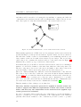
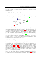


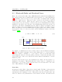
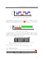
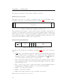
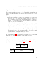
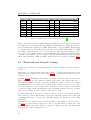


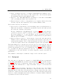
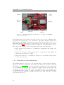


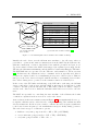
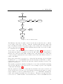
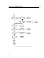


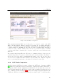

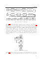


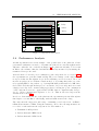
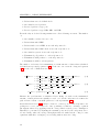

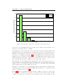
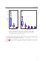


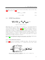
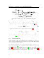


![Hacking Medical Devices - [media.blackhat.com]](http://vs1.manualzilla.com/store/data/005931227_1-f7547ce2b3ff0825b843d9b1dbb48800-150x150.png)