1
BMW, BMW MINI
Special Model Specific Harness
for
3-DRIVE
(THR-BM As of November, 2008 No.2)
3-DRIVE
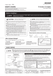
USER’S GUIDE
THROTTLE CONTROLLER
EURO SPEC
Thank you for purchasing PIVOT 3-DRIVE for BMW / MINI.
Please read both this specialized manual and the 3-DRIVE manual carefully and after
reading store in a safe place.
Please do not lose this user’s guide, as you will held liable for the cost of reissuing it.
CAUTION
Please check
the contents of
the package
Improper use or disregard of these warnings may
result in the injury or death of people.
● When carrying out work on the car make sure to turn off the engine, put into Park
or Neutral and apply the emergency brake.
● Make sure to position and fasten all units and cables in such as way as to not
cause any interference with driving.
● This product is designed for use with 3-DRIVE. Do not use with another company’s
product or try to modify the unit in any way; doing so poses danger and may cause
malfunction and/or damage to your automobile.
● Improper use may lead to “stoppage of engine”, “sudden lurches forward” and
other dangers; make sure to thoroughly read and understand the User’s Guide before using this device.
NOTE
Special Model
Specific Harness
Zip Tie
×2
User’s Guide
Improper use or disregard of these warnings may cause
injury to persons, damage the product and / or other things.
● PIVOT Corporation accepts no responsibility, in any manner whatsoever, for damage and/or trouble to your vehicle or product, nor for any accidents that are the
result of the misuse of this product.
● To properly install this product requires specialized knowledge. If you are unsure
about anything, please consult a professional at your local dealer.
● Make sure to fasten the connector in an area that is not exposed to water.
Notes for Some Car Model Types
Notes for All Models
Combined use with other Diagnostic Monitoring Connector Products
In some models the OBD2 coupler may be unsightly. If this is the case,
please see point 2 on page 3 of the [3-DRIVE User’s Manual] about
how to wire directly to the fuse box for power and earth.
BMW
Because the display is interlocked with the ECU (engine computer)
power, the display will remain on for some time even after the engine has been turned off. If operating properly, this will not affect
the car’s battery or power. Moreover, re-starting again while the display is still on will not cause any problems or trouble.
MINI
Time to lights turn off: R50/53 model = about
R56 model = about
It is possible to use in combination with other
diagnostic monitoring connector products. For
power, connect the cable to the same terminal
on the coupler of that product.
Hook
5 minutes,
OBD2 coupler
Red
Unit
Black
Normal power
= Red wier
(Far Left)
Other Product
Earth = Black wire
10 minutes
(Fifth from the left)
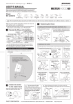
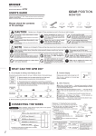
From Installing the Specialized Harness to making Initial Settings
Please follow the directions from installing the specialized harness to the making of the initial settings in the exact order as outlined below.
1
Make sure to carry out all work
in a well lit area
2
To ensure that the specialized harness is installed properly,
make sure to only carry out the installation after the accelerator pedal has been disconnected. (See below for details)
Please carry out the inserting of the connector in a well lit
place. (If carrying out in a dark place, please use a flashlight for a better view.)
Common Example of How to Remove Accelerator Pedal
Type
A
Type
Examples of Car Models;
BMW E85・E87・E60,
BMW MINI R56 etc.
① Remove the rubber cover from
the bottom of the accelerator
pedal and unscrew the screw.
Turn the engine off and remove the
accelerator pedal
B
Examples of Car Models;
BMW E46,
BMW MINI R50・R53 etc.
※ If different from shown below contact your dealer for advice.
① Dislodge the catch on the left side of the accelerator pedal with a wide (7mm or above)
flathead screwdriver.
② Lift up with the screwdriver and slide the pedal
to the left about 1 cm.
7 mm or above
Slide the pedal
to the left
about 1 cm
Accelerator
pedal
(Front)
Inside catch
(Front)
No rubber
cover
Flathead
screwdriver (Large)
There is a rubber
cover and screw
② Pull off towards the top.
③ With a thinner flathead
screwdriver
(6mm or less), insert
into the same place
as in ① .
④ Lifting up as in ②
with the screwdriver,
slide the pedal further
to the left and then
pull completely off.
③
④
6 mm or less
Accelerator
pedal
Inside catch
Flathead
screwdriver (Small)
Pull
completely
off.
Only disconnect the accelerator connector after having waited
at least ten minutes from the time that the key was turned OFF
3
Accelerator pedal
After the engine has been stopped for at least ten minutes, pull off the accelerator connector by pressing on
the hooks on the sides of the connector (female side).
LOCK
(OFF)
Turn the key
to OFF
4
Disconnect the male and female
connectors on the specialized harness
To prevent the male pins on the connector from getting bent during transport, each connector is already connected. Make sure to
pull apart evenly so as not to bend any of the pins on the male
side of the connectors.
Pull out evenly making
Accelerator
(after being removed)
sure not to bend the pins
Orange wire
Passage
of over
(Female
emale side) (Male side)
Press
Gray wire
10 minutes
Depending on the type of vehicle, if
the connector is disconnected before
the ECU power is switched OFF the
Check Lamp may go on.
(
5
Press
※ With the orange and gray wires, which connect the male
Disconnect
the connector
and female sides of the connector, at the top of the connector pull the connector apart.
☞How to turn off the Check Lamp)
Insert the male side of the specialized harness
into the female side of the accelerator connector
About insertion direction
Top side
2
3
6
5
1
(
☞How to turn off the Check Lamp)
※ To protect the connector, fasten by
wrapping insulation
tape around it.
Round
indentation up
4
Front side of the
Accelerator connector
(female side)
Connector
Insulation tape
Insert the
connector
※ If you do not have insulation tape, please
fasten using the zip
tie that is provided in
the package.
Pin to prevent inverse insertion
6
Insert the female side of the specialized harness into the male side
of the accelerator connector
Make sure to completely insert the male side into the female
side of the harness until the hook locks.
Connector of harness
(Female side)
(Male side)
Inserting with bent pins may result in poor
connection and when the engine is started
this may cause the check lamp to come
on and the vehicle to go into safety mode.
Accelerator connector
(female side)
of harness
(male side)
(Female side)
If any of the pins on the
male side are bent and
cannot be connected
properly, correct the bent
pins and insert.
Accelerator connector
(Male side)
7
Carry out the power connection instructions as written
on page 3 of the separate “3-DRIVE User’s Manual”.
【Data】Placement diagram for diagnostic monitoring
connector
②
①
④
zip tie
(included)
8
Connect to Power
③
Insert the
connector
zip tie
(included)
① At the right foot of driver seat
in the center (with lid)
② At foot of driver seat in
the center
③ At the left foot of driver seat
in the center (with lid)
④ At the right side of the
passenger seat
Run the zip tie
through the hole
Carry out the
Initial Settings
Carry out the initial settings instructions as written
on page 5 of the separate
[3-DRIVE User’s Manual].
Without carrying out the
Initial Settings, the controllers will not work properly.
How to turn off the Check Lamp and lift from Safety Mode
If all is carried out properly the Check Lamp should not come on, but if for reason it does, please carry out
the following to solve the problem.
① Under normal conditions, start and stop the engine
several times.
② If that does not turn of the lamp, please consult your
local car dealer and have them turn it off.
PIVOT CORPORATION
LOCK
(OFF)
Turn the key
to OFF
START
Check Lamp is
ON
Key ON
(Engine start)
87-3, Shimookada Okada, Matsumoto-shi, Nagano, 390-0313 Japan TEL0263-46-5901
h ttp ://p i vo t jp.com/