1
USER’S MANUAL (
Product Number :
PDX-B1
(PDX-B1 As of May, 2015 No.1)
)
Sub-Computer for BMW
POWER DRIVE
Thank you for purchasing PIVOT product.
Please read this manual carefully and keep it for future reference.
●If this product is given to another
user, make sure to include this
User’ s Manual.
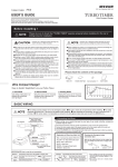
WARNING
Product
+
Improper use or disregard of these warnings may
result in the injury or death of people.
●Do not work in areas where
there is excessive exhaust.
D u e t o ve h i c l e e x h a u s t e m i s s i o n
poisoning or fire may result in a
damage to humans.
●Do not crush the cable.
Please be careful that the cable does
not get crushed by the seat rail or car
door steel plate, nor cut by any sharp
steel plate as this may cause a poor
connection or an electric short leading
to fire or other danger.
●Do not operate while driving.
Operating and checking during
d r i v i n g m ay c a u s e a n a c c i d e n t;
please use with the utmost consideration for safety.
●Please securely fasten the
product to a stable place and
be sure to store bundle away
all wires with tape, etc...
It is very dangerous to pull tangled
wires by force or allow tangled wires
to interfere with driving.
CAUTION
Improper use or disregard of these warnings may cause
injury to persons, damage the product and other things.
● Just af ter installation do not
exer t any strong force on the
product.
●Do not install the product in any
place subject to high temperature or any place where water
may be splashed.
●Make sure to replace all screws
and parts to their original place.
●Do not, in any manner, process,
take apart, or make changes to
this product.
Please note that it's easy to unstick just
after fixing the product with doublesided tape.
●Do Not Use Chemical Cleansers.
If the unit gets dirty please wipe with a
soft cloth to remove any dirt. Do not use
chemical cleansers such as thinner,
benzene, or alcohol.
1. This product cannot be installed in cars which use the different DME (engine computer) from the standard or use a
sub-computer. (can be installed with 3-drive series)
2. Cannot be displayed exact value on Boost meter using Diagnostic Monitoring Connector and Torque meter of the car.
(including PIVOT products : 52X-BM, 52X-Z4, 52X-F3 etc.)
3. If not carried out work as procedure, warning message might light.
Contents
Please check the contents of the package
WARNING / CAUTION / Contents …… 1
Features ………………………………… 1
Part Names ……………………………… 1
Connecting The Wires ………………… 2
Sensor Position of Each Vehicle Type
and Install Examples ……………… 2 ∼ 3
Installing The Product
………………… 4
Unit
Harness
Zip Ties
(Large) × 2
(Small) × 8
Double-sided
Tape
×3
Screwdriver
User’ s
Manual
[70 × 90×20 mm]
Level Adjustment ………………………… 4
Troubleshooting ………………………… 4
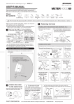
Features
Part Names
Because Power Drive (PDX-B1) is a control system based on results from actual testing of
BMW-N20 engines, you are ensured real power that suits your needs.
1
2
1
9
78
Simple Coupler Connection
Simple coupler connection within the engine
room means easy trouble-free installation.
Level Adjustment
The circuit board is protected by a double layer
waterproof coating and the sealed case is designed
to drain away water and protect from high pressure
water and condensation; ensuring long worry-free
usage.
The boost pressure can be adjusted in 9 steps
of 10% from normal to up to 1.9 times normal to
meet your needs whether driving in the city or
racing.
Power Boost with Safety Range
Besides offering boost up within your cars fuel
control range and adjusting for boost during
s t ar tu p a n d l ow water te m p er atur e, i f t h e
product should fail it will automatically return to
normal boost levels to ensure safet y while
driving.
6
Performance Boost
Power Drive gives you per formance boost ;
maximum 1.48 seconds reducing at 0-100km/h
time, power increase about 60 ps and torque up
5.8 kgm on our measured results.
4
23
3
Waterproof Drainage Design
Easy Installation with Thin Compact Unit
Thin Compact unit Installation is made easy by fixing
the unit with double-sided tape or zip ties.
※Do not install in areas prone to strong engine
vibration or extreme heat.
No Repair or Inspection Necessary
As this product makes no alterations to the DME
(engine computer), it has no impact on inspection,
repair or DME version upgrades.
1
LED ………………… Lights during operation
2
Adjustment dial… For boost level adjustment
3
Cap ………………… Cap of adjustment dial
1
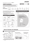
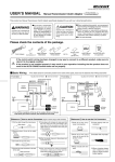
Connecting The Wires
Basic Wiring
4-pin Connector
4-pin Connector
4-pin Connector
Male
Male
Male
Unit
8-pin Connector
Female
Female
Connecting Each Sensor
Female
Yellow
Red
Blue
Intake Manifold
Sensor
Boost Pressure
Sensor
Hot-film
Air Mass
Meter
(0.7 m)
(0.7 m)
Vehicle sensor
Harness
4-pin Connector
Male
Sensor
Female
(1.2 m)
Harness
(0.3 m)
Harness
(Length from the 8-pin Connector)
Follow the procedure below when connecting. If not carried out work as procedure, warning message might light.
●Pull out the connector(Common to each model)
Connection Procedure
1
Key Switch OFF.
2
Open the hood.
3
Close all doors and lock them.
4
Wait for more then 15 minutes
after doors locked.
5
A
Remove the hook
Pull out
Connect each Sensor.
・See page 2 to 3 for the sensor position of each car type.
・Do not open the doors after finishing all connection.
6
7
Detachment
Remove the hook of car side
connector using screwdriver and
pull out.
※May also press the A section If you
can pull out
Attachment
Insert until locked.
■Unlock the connector
Connect the Harness to the Unit.
Locked state
Fasten the Unit.
Attachment and Detachment
of Car side Female connector
Lock
Unlocked state
Lock
・See page 2 to 3 for the Unit install examples of each car type.
・See page 4 for fasening.
8
Fasten the Harness.
9
Start the engine and
check the LED lights or not.
Slide the Lock to arrow direction
and pull out the connector.
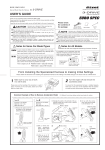
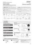
Sensor Position of Each Vehicle Type and Unit Install examples
320i/420i
Unit
(e.g. Top of the Fuse box)
Intake Manifold Sensor
Unit
Boost Pressure Sensor
Hot-film Air Mass Meter
2
523i
Intake Manifold Sensor
Boost Pressure Sensor
Hot-film Air Mass Meter
Unit
Z4 20i
Unit
(e.g. Top of the Air cleaner box)
Intake Manifold Sensor
Boost Pressure Sensor
Hot-film Air Mass Meter
Unit
X1 20i
Intake Manifold Sensor
Boost Sensor
Unit
Hot-film Air Mass Meter
3
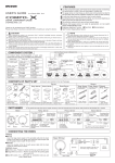
Installing The Product
●Fastening to Flat Space
●When Fastening to a Cable or Pipe
Fastening using Double-sided tape.
Not fastening with
this side down
※Do not cover the holes for drainage port
on the backside of the unit with
Double-sided tape.
Unit
Holes
Double-sided
tape
Fastening to a Thick cable
or pipe
Fastening to a Thin cable
or pipe
Zip tie (Large)
Zip tie (Small)
Fastening
3 to 4 places
Not Through
holes
Fastening
position
Zip tie (Small)
Through holes
Clean to
remove
oil and dust.
Thick cable or pipe
Hole
Thin cable or pipe
Hole
※Do not install in areas prone to strong engine vibration or extreme heat.
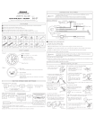
Level Adjustment
●Level Value Adjustment
901
23
Wait for the LED lights off.
456
2
Key Switch OFF.
78
1
(Usually not necessary)
Turn the arrow of
center of dial with
screwdriver.
Remove the cap.
Turn the Dial
after the LED lights off.
4
Key Switch ON.
5
Setting Completed
when the LED lights.
●Relation of Dial Numbers and Boost Pressure
Boost Pressure
3
Put back in its place.
0
1
2
3
4
5
6
7
8
Car
Moldel
If warning message displayed
If warning message displayed when you use
d i f fe r e n t p a r t s s u c h a s m u f f l e r f r o m i t s
standards, please set the level value 2 to 3
steps lower.
9
Level value
Recommended value
(Factory setting)
Normal
Peak Boost of Each Level (kPa)
0(Normal)
1
2
3
4
5
6
7
8
9
79
84
89
95
100
104
108
112
320i
60
72
420i
58
64
70
76
81
86
89
92
95
98
523i
75
88
89
90
91
92
95
98
101
105
Z4
80
97
100
102
105
108
112
116
121
126
X1
78
87
92
96
100
104
107
110
114
118
※The results shown here are from actual tests carried out by PIVOT and may differ from
other car type and conditions.
Troubleshooting
Trouble
Possible Causes
Possible Solutions
LED does not light or blinks.
Poor connection of Harness .
Please reconfirm whether wiring and connections of
Harness .
Warning message lights.
Poor connection of Harness .
Please reconfirm whether wiring and connections of
Harness and restart the engine.
Not carried out connecting as procedure order.
Please reconfirm whether wiring and connections of
Harness and restart the engine.
Not feel any differences.
Adjustment Dial is set to 0.
(0=Normal)
Please reconfirm Adjustment Dial .
※Our products have already been recognized as our Industrial Property or are in the process of receiving Industrial Property status.
※We plan in the near future to take all possible legal measures to protect against unfair competition from look-alike products using similar designs, regulating characteristics,
circuitry and circuitry layout.
※We strictly prohibit the unlicensed use of the PIVOT trademark and the unauthorized use of PIVOT User’ s Manual.
4
PIVOT CORPORATION
87-3, Shimookada Okada, Matsumoto-shi, Nagano, 390-0313 Japan TEL0263-46-5901