1
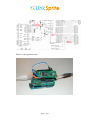
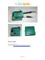
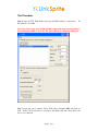
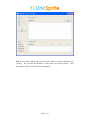
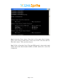
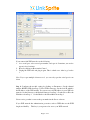
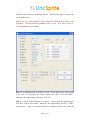
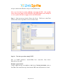
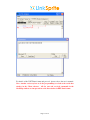
Step-by-Step Tutorial For
Using LinkSprite UARTWIFI Module Model
LS_UART_WIFI
Page 1 of 12
Hardware needed
A desktop/laptop PC with WiFi adaptor
A WiFi router
This Uart-Wifi module model number LS_UART_WIFI with antenna
A Uart-serial port converter and cable. In this tutorial, an Arduino board is used
as a UART-USB converter. Other serial interface, e.g. RS-232 is okay.
Serial port cable. In this tutorial, USB cable is used.
Hardware Connection
Use an Arduino board as a UART-USB converter. The MCU is removed. Only the
FT232RL is used in this test. The schematic is shown below.
Use an adaptor to connect the WiFi module to the Arduino board.
Connect one end of a USB cable to the Ardunio board, and the other end to a PC.
Connect the antenna to the WiFi module.
Page 2 of 12
Pictures of the experiment setup:
Page 3 of 12
Software needed
X-CTU from digi.com
PC test tool http://www.linksprite.com/pub/Test%20Tools.rar
Page 4 of 12
Test Procedure
Step 1: Open X-CTU. Find which serial port the WiFi module is connected to.
this tutorial, it is COM4.
In
Note: For some reason, only COM1~COM4 is supported in the test tool software.
If you find port COM5 or up in X-CTU, please change to a different COM port. .
Step 2: Open the server software. Select TCP, and port number 6000, and click on
Start. Before TCP connection is connected, the Remote IP and remote Port both
show “not connected”.
Page 5 of 12
Step 3: In your PC start/run, type cmd and return. Find out your IP configuration by
ipconfig. You can find the IP address, subnet mask, and default gateway. This
information will be used in the Client configuration.
Page 6 of 12
Step 4: Open the Client software. First click on Close under Serial Configure.
Select correct serial port number that is found out in X-CTU. Select the baud rate.
Then click on Open. This opens the serial port.
Step 5: Click on Scan under Control. The found WiFi network is shown in the output
window. Record the channel number, BSSID, and SSID, which will be used in the
configuration.
Page 7 of 12
If you cannot find WiFi network, try the following
1. close serial port, select correct port number, and open it. Sometimes you need to
repeat it for a few times
2. Reset by clicking on Reset under Control.
3. Unplug the USB cable and plug it again. This is a hard reset. After it, go back to
1.
Note. If you open multiple client test tool, you can only open the serial port in one
client.
Step 6: Configure the module setting by clicking on Parameters. Set the channel
number, BSSID, SSID from Step 5. Select TCP in data type. Set the local IP, which is
the IP address of the WiFi module. You can use any valid IP address in your WiFi sub
network. Set the Gateway to the Default Gateway from Step 3. Set the Server IP to the
IP Address from Step 3. Set the Mask to the Subnet Mask from Step 3.
Select service port that is same as the port number in the Server software.
If you WiFi network has authentication protection, such as WEP, then set the WEP
length, and the Key. This key is your password to access your WiFi network.
Page 8 of 12
Set the System parameters, including baud rate.
one set in the Server.
This baud rate must be same as the
Before you save your parameters, do not forget to check the box before each
parameter. Only the checked parameters will be saved. Now click on Save to
save the parameters to the module.
Step 7: Join a WiFi network by clicking on Join. Select which group of parameters
to be used. If successful, the output window will show “Join successfully”.
Otherwise, the output window will show “leave bss”.
Step 8: Connect TCP by clicking on “Connect”. If successful, the output window
will show “Connect successfully”. Otherwise, the output window will show “TCP is
disconnected”. After it is connected, the Server software will show the remote IP
Page 9 of 12
and port, which are the IP address and port of the WiFi module.
Note: try a few times if you have difficulty connecting the TCP. One possible
cause is the power supply of the USB cable to the WiFi module is not enough. If
so, use a separate DC power supply to drive the WiFi module.
Step 9: Send text message from the Client or the Server.
will show the text message that it receives from the sender.
Step 10:
The Server or the Client
Test above procedure using X-CTU.
First set UART parameters: baud=115200, flow control=No, Data bits=8,
Parity=None, Stop bit=1.
Example : Scan network
Compose HEX message AA 84 00 04 13 00 31 04 55 00 00 00 00 00 00, click on
Send Data. The returned message shows that the WiFi network Ej.mtnview is found.
Page 10 of 12
For details of the UATT data format and protocol, please refer to the user’s manual.
Note: Another easier way how to do the programming is to look at the serial data
window in the Client software. All the sent and received commands in the
Cmd/Msg window are interpreted in serial data window in HEX data format.
Page 11 of 12
LinkSprite Technologies, Inc.
Add: 1410 Cannon Mountain Dr, Longmont, CO 80503
Tel: 720-204-8599
Email: [email protected]
Technical support: [email protected]
Web: www.linksprite.com
Page 12 of 12