1
Final Report
TMS: Transcranial Magnetic Simulation
Spencer Ulven, Kaiyue Zheng, Joshua Abbott,
Zhongheng Wang, Nikhil Reddy Purma
Project Plan V2
Dec 14-06
Final Report
TMS: Transcranial Magnetic Simulation
TABLE OF CONTENTS
1. System level Design.............................................................................................................................................4
1.1 Summary of Device ......................................................................................................................................4
1.2 Project Requirements/Specifications...................................................................................................5
1.2.1 Top Level Amplifier Requirements ...............................................................................................5
1.2.2 Top Level Interface Requirements ................................................................................................5
1.3 Functional Decomposition ........................................................................................................................6
1.3.1 Power supply ..........................................................................................................................................6
1.3.2 Power storage ........................................................................................................................................6
1.3.3 Switching device....................................................................................................................................7
1.3.4 Switching device control....................................................................................................................7
2. Detailed Description ...........................................................................................................................................8
2.1 System Description ......................................................................................................................................8
2.1.1 Circuit Concept.......................................................................................................................................8
2.1.2 Design Overview ...................................................................................................................................9
2.2 User Interface .............................................................................................................................................. 11
2.2.1 TMS Control GUI ................................................................................................................................. 11
2.2.3 Coding The Ardunio .......................................................................................................................... 12
2.2.4 Coding MATLAB ................................................................................................................................. 13
2.2.5 MATLAB/Arduino.............................................................................................................................. 13
2.3 Cost .................................................................................................................................................................. 13
3. Results ................................................................................................................................................................... 15
3.1 Overview of results ................................................................................................................................... 15
3.1.1 Design Process .................................................................................................................................... 15
3.1.2 Testing Procedure ............................................................................................................................. 15
3.2 Simulation ..................................................................................................................................................... 16
3.2.1Circuit Schematic ................................................................................................................................ 16
3.2.2 Simulation Results ............................................................................................................................. 18
3.3 Hardware....................................................................................................................................................... 19
3.3.1 Enclosure............................................................................................................................................... 19
3.3.2 PCB Board ............................................................................................................................................. 20
3.3.3 Mounting Board.................................................................................................................................. 21
3.3.4 System Features ................................................................................................................................. 22
3.3.5 Inductive Load .................................................................................................................................... 23
3.4 Data Analysis ............................................................................................................................................... 25
3.4.1 Test Setup ............................................................................................................................................. 25
3.4.2 Data.......................................................................................................................................................... 26
3.4.3 Final Test ............................................................................................................................................... 30
3.4.2 Theoretical vs Actual ........................................................................................................................ 33
3.4.4 Voltage Analysis ................................................................................................................................. 35
3.5 Implementation issues/challenges .................................................................................................... 37
3.5.1 Capacitor issues .................................................................................................................................. 37
Dec 14-06
2
Final Report
TMS: Transcranial Magnetic Simulation
3.5.2 Burning components ........................................................................................................................ 37
3.5.3 Logic Components ............................................................................................................................. 37
3.5.4 PCB Design ............................................................................................................................................ 38
4. Conclusion............................................................................................................................................................ 38
5. Appendix A – Additional Information ...................................................................................................... 39
5.1 Resources ...................................................................................................................................................... 39
5.2 Literature Survey ....................................................................................................................................... 39
5.3 Acronymns.................................................................................................................................................... 40
6. Appendix B – Old PCB Design ...................................................................................................................... 40
6.1 Old Ultiboard PCB Design ....................................................................................................................... 41
6.1.1 FIlter/amplifier board ..................................................................................................................... 41
6.1.2 Discharge Board ................................................................................................................................. 41
7. Appendix C - Failures of First Design........................................................................................................ 43
7.1 Large Component Issues ......................................................................................................................... 43
7.2 PCB Design Issues ...................................................................................................................................... 43
7.3 Integration of Single PCB Board .......................................................................................................... 44
7.3.1 Old GUI ................................................................................................................................................... 44
8. Appendix D – User Manual ............................................................................................................................ 46
8.1 Power .............................................................................................................................................................. 46
8.1.1 Master Power ...................................................................................................................................... 46
8.1.2 Transformer ......................................................................................................................................... 46
8.2 Button Details .............................................................................................................................................. 47
8.2.1 Pulse Trigger........................................................................................................................................ 47
8.2.2 Discharge Capacitor .......................................................................................................................... 47
8.2.3 Mono/BiPhasic Rocker Switch ..................................................................................................... 48
8.2.4 Capacitors Charged LED.................................................................................................................. 48
8.3 GUI Instructions.......................................................................................................................................... 49
8.4 Load Specefications................................................................................................................................... 51
9. Appendix E – Bill of Materials ...................................................................................................................... 52
10. Appendix F – Arduino Code ....................................................................................................................... 54
11. Appendix G – MATLAB Code...................................................................................................................... 66
Dec 14-06
3
Final Report
TMS: Transcranial Magnetic Simulation
1. SYSTEM LEVEL DESIGN
1.1 SUMMARY OF DEVICE
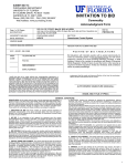
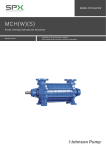
Our goal of this project was to create a high current pulse generator for the application of
Transcranial Magnetic Stimulation (TMS). Currently, extensive research is being done in the
area of TMS for many neurological conditions that could affect the human brain. For
instance, TMS is being used to treat depression, migraine headaches, as well as back and
neck pains. Future research is exploring the possible uses in other applications like
Alzheimer's disease, post-traumatic stress disorder (PTSD), Parkinson’s disease, etc.
Researchers are looking for a device that can produce the current needed to power a TMS
coil and support deep brain stimulation to help treat and further understand these severe
brain conditions.
The magnetic fields used in TMS applications are pulsed at very short time intervals. A high
current pulse is sent through an inductive coil to create these fields. The goal of this Senior
Design team was to create a device that can deliver such a pulse. This device has
controllable parameters (such as pulse width and amplitude) and produces the power
necessary for magnetic stimulation.
This document will cover the overall design, applications, results, and functionality.
Figure 1: TMS System Prototype
Dec 14-06
4
Final Report
TMS: Transcranial Magnetic Simulation
1.2 PROJECT REQUIREMENTS/SPECIFICATIONS
1.2.1 TOP LEVEL AMPLIFIER REQUIREMENTS
Functional requirements for amplifier:
Creates both monophasic and biphasic pulse waveforms
Supports 50 to 400 micro-second pulse width
Outputs 1000 Amps both negative and positive
Nonfunctional requirements for the system:
Cost under $500 dollars.
Have a graphical user interface (GUI) utilizing MATLAB.
Safe and easy to use.
1.2.2 TOP LEVEL INTERFACE REQUIREMENTS
The user interface requirements contains:
Full control of device via MATLAB GUI
Able to select between monophasic and biphasic pulse waveforms via manual
button controls on device
Button to send 400 microsecond pulse manually.
The graphical user interface requirements:
Control waveform pulse width
Control waveform pulse type
Discharge capacitors via button or upon exit of program
Show pulse waveform via real-time current data
Show charged capacitor real-time voltage data
Dec 14-06
5
Final Report
TMS: Transcranial Magnetic Simulation
1.3 FUNCTIONAL DECOMPOSITION
1.3.1 POWER SUPPLY
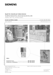
The power supply consists of a transformer, voltage quadrupler, and filter. Our circuit
begins with power from a standard wall outlet, which is adapted into wires using our power
entry connector. Those wires are then attached to our
2:1:1 transformer that steps down the voltage and splits
it
into two halves (one for positive and negative
rectification). The transformer has a current limiter
located on the secondary side of the circuit so that it
doesn’t draw over 15A. We have a voltage divider to
reduce the voltage down a bit to keep the circuit from
producing over 200V (max rating of capacitor bank). Our
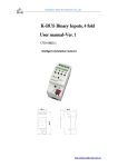
Figure 2: Toroid Transformer
voltage divider uses a 1K resistor for the beginning of the
800VA 75V
divider with a 2K resistor for the second part of the
divider. The output of this divider is 53VAC both from measured and calculated. When the
voltage is stepped down, it travels through our voltage quadrupler; this both rectifies our
signal from AC to DC and amplifies our voltage to 200VDC. The voltage quadrupler we used
consists of two Greinacher cells of opposite polarities to create positive and negative DC
voltage. In effect, the input is increased by a magnitude of four. After this, to eliminate any
rippling in the DC signal, we passed this through a resistor-inductor filter, which stabilizes
and creates a clean 190VDC. Notice that there is a 10V drop from the resistance of the
voltage quadrupler and the filter.
1.3.2 POWER STORAGE
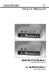
The voltage from our power source then charges our capacitor bank. The capacitors store
the voltage over small period of time which we have calculated to be around 1.5 minutes.
They hold the voltage till a path to ground is created via highpowered switch. The input from the user can choose to send a pulse
using the front panel or the graphical user interface (GUI) to
discharge these capacitors for any given period of time. If the user is
sending a pulse, the capacitors quickly discharge a small amount of its
total charge into the inductive load via IGBT. To safely handle the
capacitors, we implemented automatic capacitor discharge through
the Arduino chip. We also allow users to safely discharge the
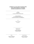
Figure 3: 10mF, 200V,
capacitors through controls on the front panel and GUI. These
Capacitor LNR2D103MSE
controls flip a solid state relay and discharge the capacitors safely into
high power resistors instead of the inductive load.
Dec 14-06
6
Final Report
TMS: Transcranial Magnetic Simulation
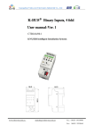
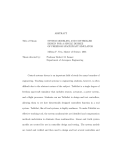
1.3.3 SWITCHING DEVICE
The switching device is a dual insulated gate bipolar transistor (IGBT) module. This module
also contains suppression diodes to protect the IGBTs from any backlash current created by
the inductive load. This component handles high
power switching at very quick speeds. This device
allows us to send either a single positive or negative
current (monophasic) or a positive and negative pulse
(biphasic). Another feature with IGBT modules is that
they are very fast switching devices. Since we are
dealing with pulse waveforms in the microsecond
range, this is essential to creating a clean square
voltage pulse. The IGBTs are rated for very small
windows that are a few microseconds long which is
Figure 4: Infineon Dual IGBT Module
quick enough to achieve the requirement of 50 to 400
FF900R12IP4
microsecond pulses.
1.3.4 SWITCHING DEVICE CONTROL
Arduino Uno controls our switching device; which determines what kind of signal will be
generated either monophasic or biphasic and the duration of the pulse. The Arduino itself
receives an input from either the front panel or the GUI. The GUI has a far greater amount of
control than the manual control on the front panel. Refer to section 1.2.2 for GUI
requirements to view the functions extensive list of functions. The front panel is only able to
send a simple 400 microsecond pulse that is either mono/biphasic and can safely discharge
the capacitors after use. The voltage pulse is first sent to an IGBT gate driver. The driver
essentially isolates the 5V signal from the large power flowing through the IGBT. This gate
driver requires a 15V floating supply which we achieve from
the transformer. The transformer has two 18VAC isolated
supplies which we convert to 15VDC. This voltage is controlled
via gate driver with a 5V pulse. Unlike MOSFETs, IGBTs are
turned on by the capacitance between the gate and emitter
(not the gate and the source). The gate driver takes the emitter
voltage of the IGBT and applies the 15V across the gate and
emitter to turn it on when 5V is being supplied it through the
Figure 5: Arduino Uno
Arduino.
Dec 14-06
7
Final Report
TMS: Transcranial Magnetic Simulation
2. DETAILED DESCRIPTION
2.1 SYSTEM DESCRIPTION
2.1.1 CIRCUIT CONCEPT
In order to create a circuit design we had to perform extensive surveying to gain a better
understanding of how to implement a high current generator. We found that nearly all
current amplifier circuits consists of large capacitors and small resistive loads. We found
that the idea is to store a lot of charge in a capacitor. Understanding the relationship
between voltage and capacitance to be Q=CV, helped us determine how to achieve a large
amount of charge. Figure 1 shows the analysis for how we determined the current through
the inductor. The equation on the left is a model for a capacitor discharging with resistance
R. The equation on the right is a model for an inductor current given an instantaneous
voltage. The total current is the bottom equation which shows how the changing capacitor
voltage as the source for the inductor.
Figure 6: Circuit Analysis
This analysis was verified by applying the previous year’s design to the equation. In doing
this, the total current was calculated to be 510A. This is exactly what the last year senior
design team observed at the output of their circuit. Knowing that this is correct, we choose
the capacitor so that the cost would be minimized but the performance would remain. Since
high voltage capacitors are expensive, we found it best to use only two (for positive and
negative charge). We also minimized the capacitance since this variable also greatly affects
the cost. We used the total current equation to make sure that our pulse will be quick
Dec 14-06
8
Final Report
TMS: Transcranial Magnetic Simulation
enough to generate a minimum of 50-microsecond pulse. We tested this analysis in
Multisim and could conclude that this is indeed the right equation for characterizing the
pulse amplitude. However, this does not include the negative edge analysis of the pulse. This
analysis has been proven to be significantly more complicated due to the capacitance of the
IGBTs. As per section 3.4.4 results, it can be seen that the output has a ripple effect after the
waveform. However, this ripple effect is so fast (322kHz), it has very little effect on our
current output. Lastly section 2.1 shows the total current equation aligns perfectly with our
actual data we have collected thus proving both theoretical and actual measurements to be
true (seen in section 3.4.2).
2.1.2 DESIGN OVERVIEW
With the concepts discussed in section 2.1.1 we designed our circuit to perform up to the
requirements given by our client. These requirements were producing monophasic and
biphasic pulse waveforms with a minimum of 1000A output. To do this we created two
branches of the circuit which both consists of three main sections: power supply, energy
storage, switching mechanism. Controls are used to send the pulse through the load. For the
power source, we are using a standard wall outlet then split the voltage using a 2:1:1
transformer. We then use a voltage quadrupler to rectify it into positive and negative DC
voltages of +/- 200V. This produces a rippling effect in our DC voltage so this voltage is sent
through a filter using a resistor and inductor so we can get an even DC voltage as an output.
The filtered voltage of +/- 200VDC charges the capacitors for both positive and negative
sides of the circuit. These banks can produce upwards of approximately 1000 Amps when
they are discharged into our inductive load via IGBT control. This IGBT module allows us to
control this high current with the ability to discharge either the positive or negative
capacitor (monophasic) or discharges the positive then negative capacitors (biphasic). Our
Arduino chip utilizes an IGBT driver for protection and is able to manage how long the IGBT
modules are conducting. The Arduino itself will be controlled by our MATLAB GUI to make
the user interface easier for people who understand the layout of the GUI better than our
button layout.
Dec 14-06
9
Final Report
TMS: Transcranial Magnetic Simulation
Figure 7: TMS Amplifier Block Diagram
From this block diagram you can see the key blocks that will be the major parts of this
circuit will be our transformer that helps us power the device and helps shield the wall from
the current surges due to the current limiter on the secondary. To further control the
current we implemented a voltage divider as mentioned in section 1.3.1 Our voltage
quadrupler is our second block that includes the use of diodes that rectify the circuit into DC
voltage and capacitors, inductors, and resistors that help filter and amplify the signal. The
10 millifarad capacitors are our most important part of this circuit since these provide us
the ability to produce the 1000 Amps of current that is required to complete the
specifications of the device. The two final important components that are needed to
complete the circuit is our IGBT module that will control the massive current for
mono/biphasic properties; this IGBT module will be connected to our Arduino. Our
inductive load is the final component in this circuit design. This coil allows our team to
create the magnetic fields that are required to use a TMS device. Our team has created two
inductive loads, which can be measured at either 32 microhenry with a resistance of 0.3
ohms, or our smaller coil, which is measured at 22 microhenry with a resistance of 0.07
ohms.
With the basic design for the circuit set, we had to find what the optimal components would
be for the circuit. In order to make such a selection, we used the circuit analysis described in
section 2.1.1 to find the cheapest capacitors. In additional, we performed wide spread
searches for components of various suppliers to ensure the device could meet the budget.
Dec 14-06
10
Final Report
TMS: Transcranial Magnetic Simulation
2.2 USER INTERFACE
2.2.1 TMS CONTROL GUI
Our team’s final version of the GUI is much more advanced and color-coded to make it easy
to operate for any potential user.
Figure 8: Final Version of GUI
Dec 14-06
11
Final Report
TMS: Transcranial Magnetic Simulation
2.2.3 CODING THE ARDUNIO
The coding for the Ardunio and MATLAB GUI required many features that the user does not
see. These features optimize the I/O of the Ardunio and allows us to use this
microcontroller as a quick and efficient controller.
Fast ADC Implantation
Analog Digital Converter has been prescaled to allow the Ardunio to measure in the
microsecond range (about 17 microseconds) rather than the default of millisecond range
(300milliseconds to read an analog pin). This part of the code breaks the analog input into
1024 steps. These means that multiplying the step value by 5 and dividing by 1023 can
translate the voltage. The voltage read is from the current sensor, which outputs a voltage
between 0 and 5 that is proportional to the current through the wire. This sensor allows one
to the read the voltage and convert it easily to current using the following equation given in
the data sheet:
𝐶𝑢𝑟𝑟𝑒𝑛𝑡 = (𝑉𝑖𝑛 − 𝑉𝑟𝑒𝑓 ) × 640
With a 2.5V reference voltage, we measured the current in the system and found it to be
very accurate.
Sampling Delay
The code also doesn’t implement delays to send the voltage pulses. Instead, each analog
read instruction takes about 17 microseconds and is used to create the pulse width. With
that in mind, the Arduino will turn on a 5V digital pin, then be reading data from the current
sensor until the pulse width has been achieved in which it shuts off. This means that we are
fully utilizing the Arduino’s capabilities.
Port Registers
Due to the delay in command speed of the digital pins, this code has also implemented
direct port access through port registers. The Atmega 328 allows you directly turn the
digital pins on and off. This minimizes processing effect on the pulse width.
For the code script used refer to the Appendix 9.
Dec 14-06
12
Final Report
TMS: Transcranial Magnetic Simulation
2.2.4 CODING MATLAB
The MATLAB code has been created to utilize serial communication with the Arduino.
Basically MATLAB is either reading the serial port or writing to it. When a user clicks a
button on the MATLAB GUI, a serial code is sent to the Arduino, which is then processed and
based on the coding of the Arduino, action is performed. Likewise, the code has been
written to listen to the Arduino when it is sending data, specifically the current sensor data.
MATLAB takes the current sensor values (which are voltage readings) and converts them to
current using the equation discussed above. We have also allowed the Arduino to calculate
the time it takes to send the pulse. This value is read by MATLAB and used to graph the
results with the raw data.
For the code script used refer to the Appendix 10.
2.2.5 MATLAB/ARDUINO
As discussed in section 2.2, the GUI will be created using Arduino-MATLAB interface. The
GUI will be constructed with the MATLAB’s GUI builder. We chose MATLAB because it is
widely used software for researchers and can be easily modified for the user’s preferences.
By creating the GUI through MATLAB we can easily interface through serial communication
to the Arduino chip. We can gather live measurements with the Arduino. MATLAB will allow
us to make very fast matrix calculations with this raw data. So far we are not entirely sure
how we will measure the current through the inductor. We are considering using a coil to
measure the magnetic field and convert that into current. With this approach, having quick
software like MATLAB can help significantly in generating the necessary data.
In addition to MATLAB, the scriptwriter for the Arduino will be used as well. Through the
Arduino software, we can write code that will allow for MATLAB to control the chip as well
as the manual controls located on the front of the physical device. We intend to use the
Arduino by writing the C code that will fully control the circuit and implement various
safety features. This means that whether the user wants to use the GUI or manually press
the controls, the Arduino will handle all I/O.
2.3 COST
One of the requirements of this device was to keep the total cost of the system below $500.
The major costs of this device were three different components, which were our
transformer, the large capacitors, and the IGBTs. All these components combined cost
around $320 so these were major concerns with the first design. Our first design was
created to keep it low cost but unfortunately we learned as the fall semester continued we
Dec 14-06
13
Final Report
TMS: Transcranial Magnetic Simulation
made mistakes with choice of components, which resulted in destruction of certain
components. Our team had a learning cost of around $104.00 dollars as seen in the table
below.
Table 1: Cost of Learning
Component
# of Destroyed
Cost
IGBT
2
$42.00
Gate Driver
8
$30.00
Solid State Relays
4
$10.00
Resistors
2
$24.00
With the realization that we destroyed our original IGBTs our team discovered we needed
an IGBT with suppression diodes. IGBTs with these diodes were much more expensive than
anything else our team bought. The cost of the new IGBT module, which was $547.00, was
greater than the original budget. Another large unforeseen cost was the casing of our team’s
device. With paying Boyd lab to create the casing and the costs of all the materials involves
the cost of the casing was found to be around $180. With all these costs added all together
the entire cost of building this device is found to be around $1300. Refer to Appendix E the
offical BOM.
Dec 14-06
14
Final Report
TMS: Transcranial Magnetic Simulation
3. RESULTS
3.1 OVERVIEW OF RESULTS
The overall design has proved to be very complex. We have achieved great results that we
will review in the sections to come but first we must look at how we got there. The process
of getting from idea to a finished product has proven to be a great deal of planning, hard
work, and teamwork.
3.1.1 DESIGN PROCESS
Figure 9: Design Process
This overall design process has been followed throughout the course of the project. Slowly
working our way from a simulation to full blown prototype has generally caused a lot of
looping in this process. Redesign has been an essential part of our design process. This
redesign effort can be seen in the appendix.
3.1.2 TESTING PROCEDURE
In order to have an effective design, testing is a key process that must be handled with great
care. When dealing with a high powered system, a simple misplacement of a component or
hand can produce catastrophic outcomes. Having a clear plan for testing is very important.
Because of this we have produced a testing procedure that has allowed us to build a reliable
and fully functioning product.
Dec 14-06
15
Final Report
TMS: Transcranial Magnetic Simulation
Figure 10: Testing Procedure
This block diagram has helped us in building our prototype. Especially in trouble shooting.
Having the ability to break down the system into blocks and isolate the errors has proven to
be very difficult but effective. In addition, increasing voltage slowly has been a great help.
For instance, we had a couple of resistors fail during testing and because of this process we
were able to know exactly what voltage they failed at so we could get resistors that were
better rated.
3.2 SIMULATION
3.2.1CIRCUIT SCHEMATIC
The full layout of our circuit is shown below and follows the diagram that is listed above.
This circuit was created in National Instruments Multisim. We first built the voltage
quadrupler and filter and then kept adding onto the circuit as each section reached the
desired output.
Dec 14-06
16
Final Report
TMS: Transcranial Magnetic Simulation
Figure 11: Multisim Circuit Design
This design was after an array of other designs. Before reaching this point, our team got
familiar with using Multisim and how to generate a circuit that will be used as our final
design. Our team used Multisim to generate different types of prototype circuits to
determine what would work to achieve our required parameters. We tested the voltage
quadrupler separately and tested each additional section to ensure the circuit was
functioning as anticipated. Our team designed multiple circuits before deciding on this final
circuit.
Dec 14-06
17
Final Report
TMS: Transcranial Magnetic Simulation
3.2.2 SIMULATION RESULTS
Figure 12: Monophasic Pulse
Figure 13: Biphasic Pulse
Dec 14-06
18
Final Report
TMS: Transcranial Magnetic Simulation
Figure 14: AC-DC Converter Output
These graphs were generated using transient analysis in Multisim. It can be seen that the
waveforms are up to specifications. The rise and fall time of the pulses are under the
intended goal of 50 microseconds and the pulse amplitude reaches the minimum of 1kA.
When these results were obtained our team moved onto building phase. Our team ordered
our first wave of parts at the end of spring semester so when our team arrived for fall we
would be able to begin fabrication of the circuit.
3.3 HARDWARE
3.3.1 ENCLOSURE
The Enclosure was built at the Boyd lab at Iowa State University. It was then further
customized by the group to accommodate for all the buttons and enclosure features
outlined in section 4.2.4. The results from our design are shown in the figure below.
AutoCAD 3D was used to create our casing, which was made on campus through Boyd Lab
located inside of Hoover Hall. The casing was hand measured to make sure it could fit all of
our components and PCB inside to safely protect any potential users from any type of
possible injury. The casing was designed to have airflow to help cool any component that
might heat up. To achieve this, our team implemented a mesh of metal in the front and two
circular holes in the back for two fans. This was designed so that the fans could suck in air
through the mesh and blow out through the circular holes. Another aspect of the casing is
the I/O port for our Arduino UNO, which is connected to the computer to interface with the
MATLAB. The push buttons to control the circuit through the Arduino are mounted in the
front of the enclosure. The green button is to send the pulse and red to discharge the
capacitors. There is also a rocker switch to designate what type of pulse either
mono/biphasic. There are also other buttons such as the transformer on/off switch and a
Dec 14-06
19
Final Report
TMS: Transcranial Magnetic Simulation
LED light that indicates if the capacitors are charged or not. These are all located on the
front panel of the casing. Handles on either side of the enclosure are fixed based on the
center of gravity. The power entry connector is mounted in between the fans so that it is
easier to connect to the transformer. Overall, our casing design was done in such a way that
it looks more professional and safer to use for long term.
Figure 15: Enclosure AutoCAD 3D
3.3.2 PCB BOARD
Our final PCB board design is shown below. This was redesigned from the previous
semester (refer to Appendix for more information of previous design). This was done using
National Instruments Ultiboard.
Figure 16: PCB Design
Dec 14-06
20
Final Report
TMS: Transcranial Magnetic Simulation
3.3.3 MOUNTING BOARD
In order to secure all the components of this system, we created a mounting board that
could hold many of the non-PCB components.
Figure 17: Mounting Board
This aluminum sheet was easy to manipulate and drill into. This allows maintenance on the
system to be easy since this whole plate can be removed from the enclosure. It also allowed
us to elevate the PCB and make many of the wired connections underneath the board rather
than cluttering up the top.
Dec 14-06
21
Final Report
TMS: Transcranial Magnetic Simulation
3.3.4 SYSTEM FEATURES
In addition to these hardware components there were many features that we added to
enhance the overall prototype design. The below buttons are all powered by a 15VDC power
supply that takes the 120VAC from the wall and converts it. These buttons allow the user to
control the circuit manually without. When the big red switch is off, the 15VDC power still
stays on along with the Arduino. This allows the user to flip the transformer on and off
without losing the controls of the circuit.
Figure 18: Front Panel Controls
Figure 19: Back Panel Fans and Power Entry
Dec 14-06
22
Final Report
TMS: Transcranial Magnetic Simulation
3.3.5 INDUCTIVE LOAD
The inductive load is one of the most crucial parts of the circuit. The reason for this is that
the resistance and the inductance of the load determine all the parameters of the pulse.
Although the system has a vast array of abilities, they can only be accessed with the right
load. Considering that the resistance determines the max current and the inductance
determines the rise time, we had to carefully consider our coil parameters. For this, we built
two different coils. The first coil had the following parameters.
Figure 20: Coil 1 Design
Table 2: Coil 1 Parameters
Parameter
Value
Coil Type
Solenoid
Length
.1524 m
Radius
.0143 m
Number of Turns
50
Wire AWG
10
LRC Meter Inductance
22µH
LRC Meter Resistance
.3 Ω
Theoretical Inductance
Dec 14-06
23
Final Report
TMS: Transcranial Magnetic Simulation
Figure 21: Coil 2 Design
Table 3: Coil 2 Parameters
Parameter
Value
Coil Type
Solenoid
Length
.1524 m
Radius
.0143 m
Number of Turns
52
Wire AWG
10
LRC Meter Inductance
32µH
LRC Meter Resistance
.07 Ω
Theoretical Inductance
Dec 14-06
24
Final Report
TMS: Transcranial Magnetic Simulation
3.4 DATA ANALYSIS
3.4.1 TEST SETUP
In order to test our system once we completed it, we first ran our finished system outside of
the enclosure to allow for quick changes if needed. During our out of box testing, the main
goal was to break something out of box rather than later when it would be more difficult to
fix. This helped us troubleshoot some issues and make minor modifications to the circuit.
The main instruments used for the test setup can be seen in the table below.
Table 4: Instruments for Testing
Instrument
Model
Use
Digital Multimeter
Agilent 34410 A
Used to measure
capacitor bank voltages
levels.
Power Supply
Agilent E3631A
Used to check current
draw and test individual
components
Oscilloscope
Agilent DSO-X 2024A
Used to capture voltage
across inductor
The typical setup for this system is shown below. Notice that the DMM is hooked to the
capacitor bank inside the system. The current is read through the senor which is hooked to
the coil.
Figure 22: Typical Testing Setup
Dec 14-06
25
Final Report
TMS: Transcranial Magnetic Simulation
3.4.2 DATA
Test 1
For the first test, we hooked up coil 1, charged the circuit up to 100V and discharged it into
our load. The accuracy of the current sensor was set to round to the nearest 10th. This
means that the voltage steps to 0.1V, which amounted to 64A. The below output is the result
from the GUI and the current accuracy, therefore is +/-64A. This may seem like a significant
amount but for the first test we really just wanted to see a clean and simple pulse.
Figure 23: Coil 1, 50V Negative Monophasic (0.1V accuracy)
For this capture, the GUI wasn’t quite finished so the axes and title were not included but it
is apparent that the first test produced -450A over a 1500µs pulse width. As you can see the
inductor charged up to its full charge. The Arduino in this test only produced an 800µs
voltage pulse then stopped to allow the inductor to begin discharging.
Test 2
The next test was to see if we could produce a positive monophasic pulse in 400µs. This test
was done at 100V with coil 1. Below are the results from this test using 0.1V accuracy.
Dec 14-06
26
Final Report
TMS: Transcranial Magnetic Simulation
Figure 24: Coil 1, 100V Positive Monophasic (0.1V Accuracy)
Test 3
At this point, these results are simply not very accurate. The 0.1V accuracy causes a very
choppy waveform and gives us an unreliable result. To create a nice smooth and accurate
wave, we must look at the voltage up to the nearest 1000th. This will be helpful because each
step of the digitizer is accurate to this degree. Below is the result from a 100V monophasic
pulse with the same load except with a much higher accuracy. This accuracy gives a current
that is +/-6.4A instead of +/-64A.
Dec 14-06
27
Final Report
TMS: Transcranial Magnetic Simulation
Figure 25: Coil 1, 100V Positive Monophasic (.01 Accuracy)
It can be seen that there is a drastic difference in magnitude and clarity when we consider
the extra data. Now we get a very clean 450A monophasic pulse.
Test 4
The monophasic produce a nice clean and accurate wave at half current. We wanted to test
the functionality of the biphasic capabilities of the circuit. Below is the graph of the biphasic
pulse created using the GUI.
Figure 26: Coil 1, 130V Biphasic (.01 Accuracy)
This pulse proved the requirements for pulse shape have been met. It can be seen that the
transition from positive to negative has a small 0 current. This is due to the 50µs delay
Dec 14-06
28
Final Report
TMS: Transcranial Magnetic Simulation
imposed in the code to protect the circuit. For instance, if one were to simultaneously
switch between positive and negative, there could be a voltage potential much higher than
the intended amount. If the coil was charged to a high positive voltage and the negative side
was flipped on, the voltage potential would be just -130V, but -130V – Voltage in coil.
Test 5
In order to reach the current levels required for the circuit, we had to change out our
voltage divider to allow the capacitors to charge up to 190V. At this voltage level, we
expected 1000A territory. We also at this point in the testing created coil 2 to reduce the
resistance and therefore drive the current up. Below is the result of 190V discharge into our
coil 1.
Figure 27: Coil 1, 190V Monophasic (.01V Accuracy)
Test 6
The final test to finally get break the 1000A barrier was done by inserting our coil 2 into the
circuit and pulsing it. Below is the result of coil 2 with a 190V potential.
Dec 14-06
29
Final Report
TMS: Transcranial Magnetic Simulation
Figure 28: Coil 2, 190V Monophasic (.01V Accuracy)
This pulse shows the results of the circuit. This monophasic pulse that exceeds 1000A has
proved the functionality of the circuit.
3.4.3 FINAL TEST
The final test consisted the circuit being charged to max voltage (195V) and discharged
positive monophasic waveform, negative monophasic waveform, and biphasic waveform.
Dec 14-06
30
Final Report
TMS: Transcranial Magnetic Simulation
Figure 29: Positive Monophasic 195V (Load=Coil 2)
Figure 30: Negative Monophasic 195V (Load=Coil 2)
Dec 14-06
31
Final Report
TMS: Transcranial Magnetic Simulation
Figure 31: Biphasic 195V (Load = Coil 2)
It can be seen that the results turned out phenomenal and that the system exceeds the pulse
requirement of 1000A. In addition, the pulse width can be manipulated using the GUI as
shown below. It is important to note that the current sensor can only measure accurately up
to 1200A. This means that if a current like 1400A is given (as shown above), this value could
easily be higher than what is observed due to the current sensor equation.
Figure 32: Monophasic 100µs Pulse
Figure 33: Monophasic 200 µs Pulse
Dec 14-06
32
Final Report
TMS: Transcranial Magnetic Simulation
Figure 34: Biphasic 100us Pulses
3.4.2 THEORETICAL VS ACTUAL
Although the graphs look to be promising, we wanted to prove theoretically that the
readings the current sensors are giving us are truly correct. To do this, we went back to the
circuit analysis that was done fall semester shown in section 2.1.1. We put the measured
values of the inductive load in to the equation and plotted the result over the graph attained
in test 6. The result is shown below.
Dec 14-06
33
Final Report
TMS: Transcranial Magnetic Simulation
Figure 35: Actual vs Theoretical Current Output
The results show that the values are very closely related and therefore prove that our
current sensor and analysis are in agreement.
Dec 14-06
34
Final Report
TMS: Transcranial Magnetic Simulation
3.4.4 VOLTAGE ANALYSIS
In addition to measuring the current we wanted to look at the potential across the inductor
during these high current pulses. The voltage pulse of the corresponding current pulses
shown above is shown below.
Figure 36: Voltage Across Inductor Monophasic
Figure 37: Voltage Across Inductor Biphasic
Dec 14-06
35
Final Report
TMS: Transcranial Magnetic Simulation
It can be seen that the voltage pulse is 200µs. immediately after the circuit stops charging
the coil; the coil kicks back the voltage which drives the current down. In a sense the voltage
shows that the current through the inductor has a differential relationship. If we
differentiate the current we get a similar voltage pulse. This is found with Ohm’s law for
voltage and current in an inductor.
𝑉(𝑡) = 𝐿 ×
𝑑𝑖
𝑑𝑡
Although our voltage pulse agrees with the current pulse, we must look at the very large
ripple voltage, which is after the voltage pulse. This ripple can be attributed to the inductor
capacitor ringing which is shown in the figure below.
Figure 38: LC Voltage Ringing
Notice the ringing frequency is around 323kHz. This frequency is so high that it has minimal
effect on our inductor. Perhaps if the coil had a smaller inductance, this ringing would effect
the current more. With such a high frequency ringing however, this is essential negligible.
The voltage sample is not positive or negative long enough to produce a substantial current
that is big enough for the current sensor to pick up (6 Amp).
Dec 14-06
36
Final Report
TMS: Transcranial Magnetic Simulation
3.5 IMPLEMENTATION ISSUES/CHALLENGES
3.5.1 CAPACITOR ISSUES
Some of the issues our group encountered were how to create the required 1000 Amps
while having our capacitors being a reasonable price and size. The reason as to why the
possible capacitors were expensive was because the high capacitance and the high voltage
rating. We solved this issue by finding reasonable sized capacitors of 10 millifarads. Our
team decided on this size of capacitor due to the amount of current that needs to be
generated. The voltage rating on these capacitors is high which is found to be around 200
volts due to the high voltage from our voltage quadrupler. Our group managed to find the
capacitors needed to make this circuit work, although we neglected to consider how large
these could be. Our capacitors are around 4 inches tall and about 1.5 inches in diameter.
This causes our circuit to become very bulky and increasingly difficult to arrange. Another
issue we had was with our smaller capacitors. This was due to the fact that they needed to
be polarized for our circuit to work completely instead of ceramic, which is what our group
ordered. We soon discovered that polarized capacitors did not reach as far down as ceramic
ones so we had to sacrifice a steadier DC for our circuit to completely working.
3.5.2 BURNING COMPONENTS
Due to working with high levels of current and voltage, our group needed to find
components that would not burn out quickly. This was seen in the last group’s project
where our advisor Robert was burning out components trying to work their circuit. Our
group wants to avoid that happening so we researched and found various components that
will be able handle the amount of power the circuit creates. Our group found out that even if
we researched for highly rated components, there was still going to be destroyed
components due to the high voltage and current we created using this circuit. Due to this,
our group had to reorder more parts. This is especially true with our logic components,
which we will discuss in section 2.4.3
3.5.3 LOGIC COMPONENTS
One of the major obstacles our group encountered while building this circuit was our basic
understanding of our logic components that helped our Arduino UNO run the circuit. The
logic components that gave us trouble was our IGBT module, gate drivers, and our relays.
Our group did not fully understand how to operate an IGBT. After much research and
testing with dummy IGBTs, we finally understood that it was the voltage difference between
Dec 14-06
37
Final Report
TMS: Transcranial Magnetic Simulation
the voltage applied to the gate and emitter of the IGBT that triggered the IGBT to turn on
and off. So essentially we discovered that the Vge potential control it all we had to do was
find a way to keep the potential difference in-between 15-24V when gathering high voltage
with it. To deal with this obstacle we implemented the floating voltage supplies that came
with our transformer to compensate to safely control this potential difference. After the
IGBT problem was overcome, we then moved onto how to safely use both the relays and
gate drivers.
3.5.4 PCB DESIGN
When our team first received our parts, there were many issues with the PCB board such as
the capacitors did not fit directly on the board as was designed. Another was that we soon
found out that placed the transformer leads in the wrong area whereas our design calls for a
lead at the beginning of the circuit and the other lead connecting to the bridge rectification
to create the quadrupling effect. Where seen with the old PCB filter board we had both
connections at the beginning. It did not take long to discover this fact but problems like this
can greatly slow down testing.
With the design flaws of our first PCB design and how much space two boards were taking
up, our team decided to condense the two boards into one and have the inductors and
capacitors mounted off board. With the big components mounted onto the casing itself.
Reworking the PCB board our group, also created more relays to discharge all the larger
capacitors to reduce the risk of the circuit and cleaned up the logic side of this board
4. CONCLUSION
The goal of this project was to create a device that could one day save lives and improve the
quality of life for those of difficult circumstance. Our team has provided a descriptive
process on how this circuit works and how to put this circuit together to create the
specifications needed. Overall, we were able to deliver an effective system with the desired
features to help develop TMS for future applications.
Dec 14-06
38
Final Report
TMS: Transcranial Magnetic Simulation
5. APPENDIX A – ADDITIONAL INFORMATION
5.1 RESOURCES
To accomplish the goals of this project, we had to use resources from our advisor and to
other resources that we found ourselves. A comprehensive list is shown below:
Resources from Iowa State University:
Iowa State University will provide a budget for the design, testing, and
implementation of the design.
Will fulfill all purchase orders.
Will provide any tools needed for fabrication.
Resources from the group:
The resources we are using are the ones given to us by Robert. These resources show the
group how TMS is used and what it is, the risks of using TMS and how to safely use these
devices and how it affects the body from high levels of electromagnetism due to the coils
that will be powered by the devices. Basically the literature surveys helped the group better
understand how these TMS devices work and the effect they can have on the people around
them.
5.2 LITERATURE SURVEY
TMS Overview Document:
http://ieeexplore.ieee.org/xpls/abs_all.jsp?arnumber=6695887&tag=1
Previous Design:
http://seniord.ece.iastate.edu/dec1306/uploads/1/8/1/8/18188693/dec1306_design_doc_v2.pdf
Safety document:
http://bic.berkeley.edu/sites/default/files/Rossi_09_TMS safety review.pdf
Coils:
Coil Link
Dec 14-06
39
Final Report
TMS: Transcranial Magnetic Simulation
High Current Design
http://www.ph.utexas.edu/~espg/paper/118.pdf
High Current Design Theory
https://www.jlab.org/ir/MITSeries/V5.PDF
Electromagnetic Radiation
http://advances.uniza.sk/index.php/AEEE/article/viewFile/473/263
5.3 ACRONYMNS
TMS
GUI
PTSD
Transcranial Magnetic Stimulation
Graphical User Interface
Post-traumatic stress disorder
6. APPENDIX B – OLD PCB DESIGN
The first part of the design process requires drafting and analysis. This means creating the
circuit and forming a foundation for the circuit design. Multisim then allows us to create any
circuit design and thoroughly test it. We measured all voltage and current input and
outputs. When the desired output is achieved, we created small-scale circuits using
breadboards to verify that the simulation results held true. When this was not the case, we
reverted back to the drafting and circuit analysis and make the necessary changes in
Multisim. When Multisim provided results that were favorable we modeled a small-scale
circuit to ensure that the design worked before we ordered the many expensive parts
needed for this device. When our team received our parts we started to fabricate the circuit
to verify our, we moved on to building and verifying the full-scale model is working up to
specs. Any problems at this stage were resolved through full-scale circuit modifications. Our
group tested the circuit components before constructing the circuit. Once we fabricated the
components together on PCB boards and get everything connected we ran extensive tests to
verify requirements many of these tests were delayed due to circuit malfunctioning and/or
human error. We then started to optimize our circuit and make necessary changes to
increase its functionality and reliability. To do this, we used DMMs, and oscilloscopes to
measure and record data. The data was documented and analyzed in order to keep track of
circuit modifications and performance. Doing this our team discovered many flaws that
could call for a redesign of the device that would make it much more efficient. So to describe
our old design and the flaws it had this appendix will explain what our team did for the first
design and how it was fixed for the newer better design.
Dec 14-06
40
Final Report
TMS: Transcranial Magnetic Simulation
6.1 OLD ULTIBOARD PCB DESIGN
6.1.1 FILTER/AMPLIFIER BOARD
Our first attempt at designing our device our team created two PCB boards that connected
all the components with copper layering. We created two boards in order to isolate the high
current portion of the circuit. On one board we had our filter/amplifier with our voltage
quadrupler, rectifier, and filters. The filters are just attached to the board and were
connected by soldering the wires onto the copper lines.
Figure 39: Old Filter Board
6.1.2 DISCHARGE BOARD
The second board held our capacitors, discharge resistors, IGBT’s, and the TMS coil. On this
board we had some of our components connected via jumper wires from the other board or
the Arduino. The Arduino was planned to be connected to the IGBTs via wires to be able to
control the pulses. These pulses would have determined either a monophasic or biphasic
Dec 14-06
41
Final Report
TMS: Transcranial Magnetic Simulation
pulse. The Arduino would have also controlled the relays for discharging the capacitors. Our
inductive load was located at the end of the circuit. This inductive load was to be
interchangeable for different coils to allow for various outputs.
Figure 40: Old Discharge Board
The 3-D representation of both these boards are shown below to give the circuit a physical
representation. When our team received these boards our fabricated circuit looked nothing
like figure 13 due to many errors that were involved with the design process which will be
explained later.
Figure 41: 3-D Design of Old Board
Dec 14-06
42
Final Report
TMS: Transcranial Magnetic Simulation
7. APPENDIX C - FAILURES OF FIRST DESIGN
7.1 LARGE COMPONENT ISSUES
When our team first received our parts there were many issues with the PCB board such as
the capacitors did not fit directly on the board as was designed. The reason for this was that
when we researched the size of the capacitors the datasheet was unclear about the exact
length the pins were apart. So due to this error we had to have our four large capacitors
attached with wire jumpers and were located far from the actual circuit board. While this
was great for testing the circuit and it could have endangered any potential operator since
the pins were facing up and they were not securely attached to a fixed point. During all this
testing our team decided that when our casing was fabricated we would mount the
capacitors off board to save area inside the casing. Our team also found this to be true with
our inductors that helped filter our DC wave. Our power resistors were not the size we
thought they were so that also had to be off board also. The inductive coils were also
mounted off board and onto our mounting board. If you would like to know more about the
mounting board please refer to section 3.3.3. The TMS Coil was also moved off board to
allow for easier integration of different coils that could be used.
7.2 PCB DESIGN ISSUES
Our team encountered many small issues that came from our first PCB design. Some of
those have been mentioned above in section 2.1, but there were many small issues that
made creating a new design much more efficient. When creating the first design the board’s
holes were created too large so much more soldering was done to hold the components in
place and to create continuity. The biggest problem with these was with diodes that were a
part of the quadrupler so this could have been a design flaw. The transformer leads were
also placed in the wrong area as seen in our filter board design Figure 11 both leads were at
the beginning. This is an error due to the fact that the only way the quadrupler would work
if one of the transformer leads were directly connected to the center point of the diode
rectification. Our team did not realize this error until a few weeks after fabricating the
Dec 14-06
43
Final Report
TMS: Transcranial Magnetic Simulation
board. This led to a delay in productivity that severely hurt our team’s progress until this
problem was discovered. The final small problem was the organization of the board and the
fact that our team needed to have two more relays to discharge the capacitors. As seen in
the discharge board figure 31 the overall organization of the gate drivers and relays were
not consistent and needed to be grouped together to allow for easier recognition and wiring
for the Arduino inputs.
7.3 INTEGRATION OF SINGLE PCB BOARD
While testing and creating the casing using AUTOCAD our team realized that with two
boards the casing of the whole circuit would be incredibly large. Due to one of our goals to
make the device easily portable this called for a new design, so both of the boards were
combined into one by having all the large components mounted off board and connected via
jumper wires. This redesign was our second attempt at creating PCB boards and with this
came the experience our team did not have the first semester. Our team recognized many of
our problems and implemented fixes to correct our numerous design flaws, as seen with the
new design how it utilizes as much space as possible without errors. While During this
redesign our group was also had a better understanding of how our gate drivers worked so
we had to implement the floating supplies from our transformer to allow them to work
without being destroyed. So as seen from the final PCB design the floating supplies are
implemented and also rectified to create the VDC needed for the drivers to operate.
7.3.1 OLD GUI
Figure 42: Old Gui
Dec 14-06
44
Final Report
TMS: Transcranial Magnetic Simulation
The first attempt at making a MATLAB GUI is extremely different than our final result as
shown earlier in the document. This attempt at making the GUI was made with the very
basic functions in mind without thinking of color coding the buttons or creating a inductor
variable calculator to help with the calculations.
Dec 14-06
45
Final Report
TMS: Transcranial Magnetic Simulation
8. APPENDIX D – USER MANUAL
8.1 POWER
8.1.1 MASTER POWER
To be able to apply the input voltage for our circuit first the master power switch must be
turned on. This switch is located on the backside of the casing underneath the fans. In figure
1 will show it in the off position on the left and the on position on the right.
Figure 43: Master Power OFF/ON
8.1.2 TRANSFORMER
The button to turn on the transformer is located on the front panel and is the large red
ON/OFF switch button that lights up when the master power is turned on. Figure 2 will
show the button lit up with it in the OFF and ON positions.
Dec 14-06
46
Final Report
TMS: Transcranial Magnetic Simulation
Figure 44: Transformer/Circuit OFF/ON
8.2 BUTTON DETAILS
8.2.1 PULSE TRIGGER
The hardwired push-button to send the 400-microsecond pulse is located on the far right in
the front of the casing. To trigger this button all the user needs to do is push the button
down until the green LED inside triggers to be on and then will send its pulse. The function
of this button is wired through the Arduino UNO to send a 5V pulse to trigger the gate driver
to turn on the IGBT.
Figure 45: Pulse Trigger button
8.2.2 DISCHARGE CAPACITOR
The hardwired push-button to discharge all of the large capacitors is located to the left of
the pulse trigger green LED push-button. To trigger this button the user needs to push the
Dec 14-06
47
Final Report
TMS: Transcranial Magnetic Simulation
button down until the red LED activates. When the button activates the button tells the
Arduino to send a 5V pulse to our relays to active the switch to connect the capacitors to the
discharge resistors for two minutes.
Figure 46: Discharge Capacitor button
8.2.3 MONO/BIPHASIC ROCKER SWITCH
This rocker switch determines which type of pulse is being used either monophasic or
biphasic. To select the biphasic pulse the switch will be pushed over to the left side, and to
select monophasic pulse the switch will be on the right. If the switch is in the neutral
position a pulse will not be sent.
Figure 47: Rocker Switch in all three positions
8.2.4 CAPACITORS CHARGED LED
The LED on the far left of the front of the casing will show when the capacitors are charged
or discharged. If the capacitors are charged the LED will be on to warn the operators that
the circuit is active. The LED will be off when the circuit is discharged to a low amount of
voltage and will signal the circuit is safe to move, operate, or to touch.
Dec 14-06
48
Final Report
TMS: Transcranial Magnetic Simulation
Figure 48: Capacitor Charged LED ON/OFF
8.3 GUI INSTRUCTIONS
Our team designed a MATLAB GUI to make control the circuit with more precision than with
hardwire buttons. Each function of this GUI will be described in a table that makes potential
users able to understand each of its functions.
Figure 49: MATLAB GUI
Table 5: Buttons for GUI Descriptions
Dec 14-06
49
Final Report
TMS: Transcranial Magnetic Simulation
Buttons For GUI
The Arduino button for the GUI allows the
user to connect/disconnect the Arduino
to/from the MATLAB application. When
the Arduino is connected or disconnected
completely the text box will display that it
has been safely connected or disconnected.
The Pulse and Record button sends an
input pulse to the Arduino for it to send its
5V pulse into the gate drivers for 200
microseconds to trigger our IGBT and
creates our 400 microsecond current
pulse. This button records its data by
reading the output of the current sensor,
which is attached to the inductive load. The
Arduino reads this sensor and outputs the
current read through its digital pins.
The Capacitor Discharge button sends an
input pulse to the Arduino for it to send its
5V pulse into all four relays to discharge all
the large capacitors through our high
wattage resistors. The relays are on for two
minutes to ensure the capacitors are fully
discharged.
This Pulse Type button tells the Arduino
what type of pulse the user wants. This
means this button tells the Arduino to send
a 5V pulse to a single gate driver. While for
a biphasic pulse it sends a 5V pulse to one
gate driver then waits 50 microseconds to
send the second pulse to the other gate
driver.
This Pulse Length button determines the
length of the pulse.
Dec 14-06
50
Final Report
TMS: Transcranial Magnetic Simulation
8.4 LOAD SPECEFICATIONS
Dec 14-06
51
Final Report
TMS: Transcranial Magnetic Simulation
9. APPENDIX E – BILL OF MATERIALS
Quantity Distributor part #
Distributor
Part
Model#
4 493-7329-ND
Digi-Key
(4)Capacitor
LNR2D103MSE
2 80-C315C101K2G
MOUSER
(2)Filter
C315C101K2G5TA
1 AN-8475
AnTek
Toroidal Transformer
AN-8475
2 158SA-ND
Digi-Key
(2)Inductor
158SA
2 684-MP9100-50
MOUSER
(2)Resistor
MP9100-50.01%
714 RH0502K000FE02
MOUSER
(4)Resistor (Cap Discharge)
4 15ETH03PBF-ND
Digi-Key
(4)Diodes (Rectifier)
4 647-UVY2D0R1MED
MOUSER
2 VO03150A
4 782-LH1500AAB
Unit
Price
Total
Price
Link
$54.68 $218.72 Digikey Link
$0.36
$0.72 MOUSER Link
$84.00
$84.00 AnTek Link
$8.37
$16.74 Digikey Link
$10.90
$21.80 MOUSER Link
$4.25
$17.00 MOUSER Link
VS-15ETH03PBF
$1.54
$6.16 Digikey Link
.1 uf Cap
UVY2D0R1MED
$0.27
MOUSER
$1.08 Link
MOUSER
(2)IGBT (Driver)
TC4420EOA
$1.30
$2.60 MOUSER Link
MOUSER
(4)Relay (Cap discharge)
LH1500AAB
$2.31
$9.24 MOUSER Link
RH0502K000FE02
1
PCB board
$30.00
$30.00
$40.00
$40.00
1
Newark
Current transducer
1 612-R5BBLKREDFF1
MOUSER
Button (ON-OFF)
1 #847781028362
Superbrightleds
1 EG1841-ND
Digi-Key
$2.53
$2.53 MOUSER Link
Button (Cap charge/discharge) CPBT-SPR
$4.95
$4.95 Sbl Link
RockerSwitch(mono/biphasic) R1966DBLKBLKCF
$1.74
$1.74 delta
Dec 14-06
R5BBLKREDFF1
52
Final Report
TMS: Transcranial Magnetic Simulation
1 1144-1033-ND
Digi-Key
1 668933
Power Entry Connector
06AE2
$12.90
$12.90 Digikey Link
THE HOME DEPOT Ground Bar
EC3GB27
$12.54
$12.54 THD Link
1 995-AS32-10015
MOUSER
Current Limiter
AS32 10015
1 782-A000066
MOUSER
Proccessor (Arduino UNO)
2 N82E16835103052
newegg
$6.52
$6.52 MOUSER Link
Arduino
$24.51
$24.51 MOUSER Link
Cooling Fan
R4-S2S-124K-GP
$16.99
$16.99 newegg Link
1 LED red diffused 20mm gravitech
Warning LED
LED-RED-20MM
$1.95
gravitech
$1.95 Link
1 #847781035971
Button (Pulse control)
CPBT-SPG
$4.95
$4.95 Sbl Link
Superbrightleds
Case materials &
manufacture( Boyd labs at
Iowa State University)
1
1 641-FF900R12IP4
MOUSER
DUAL IGBT
1
Lowe's
piano hinge
1 ECF504-12BBS
USB type B compler 12''
4
Penn-elcom F1691 Rubber
Cabinet foot
$180.00 $180.00
FF900R12IP4
MOUSER
$546.66 $546.66 Link
$6.98
$6.98
$10.45
$10.45
$1.98
$7.91
4 279-THS501K0J
MOUSER
1k 50W Resistor
THS501K0J
$2.95
MOUSER
$11.80 Link
2 280-CR10-7.5K-RC
MOUSER
7.5k 10W resistor
280-CR10-7.5KRC
$0.60
MOUSER
$1.20 Link
Total
cost
56
Dec 14-06
$1,302.64
53
Final Report
TMS: Transcranial Magnetic Simulation
10. APPENDIX F – ARDUINO CODE
//////////////////////////////////////////
// Joshua Abbott
// DEC14-06 Senior Design
// 12/9/2014
// TMS Control Code
// This code works with the MATLAB code 'LEDS.m' to
// perform various controls to the TMS Device created
/////////////////////////////////////////
//These are the variables for the progra
//Used to calculate time
unsigned long time;
unsigned long startTime;
unsigned long endTime;
unsigned long start_times[20];
unsigned long stop_times[20];
//Analog pin A0 values that are read from current sensor
unsigned long values[45];
int Apin=A0; // This pin must to the current sensor pin 3
int led7=7; //This must go to positive side gate driver input
int led6=6; //This must go to negative side gate driver input
//This pins should be attached to the 4 relays on the PCB board
//for discharging capacitors
int led13=13;
int led12=12;
int led11=11;
int led10=10;
//These pins must go to Discharge and Monopohasic switch
int led9=9;
int led8=8;
int led2=2; //Monophasic select line
int led3=3; //Biphasic select line
int led4=4; //Clown nose
int led5=5; //Supply for Mono/Bi check
//front pnale variables
int Biphasic;
int Monophasic;
int Discharge;
int Pulse;
int prevBiphasic;
int prevMonophasic;
int prevDischarge;
Dec 14-06
54
Final Report
TMS: Transcranial Magnetic Simulation
int prevPulse;
const unsigned char PS_16 = (1 << ADPS2);
const unsigned char PS_128 = (1 << ADPS2) | (1 << ADPS1) | (1 << ADPS0);
void setup() {
int start ;
int i ;
pinMode(Apin,INPUT);
pinMode(led7,OUTPUT);
pinMode(led6,OUTPUT);
pinMode(led13,OUTPUT);
pinMode(led12,OUTPUT);
pinMode(led11,OUTPUT);
pinMode(led10,OUTPUT);
pinMode(led5,INPUT);
pinMode(led4,OUTPUT);
pinMode(led9,INPUT);
pinMode(led8,INPUT);
pinMode(led2,OUTPUT);
pinMode(led3,OUTPUT);
// set up the ADC
ADCSRA &= ~PS_128; // remove bits set by Arduino library
// you can choose a prescaler from above.
// PS_16, PS_32, PS_64 or PS_128
ADCSRA |= PS_16; // set our own prescaler to 64
Biphasic=0;
Monophasic=0;
Discharge=0;
Pulse=0;
Serial.begin(9600) ;
for (i = 0 ; i < 7; i++)
analogRead(0) ;
}
void loop() {
int unoin=Serial.read(); // waits for command from serial input
prevBiphasic = Biphasic;
prevMonophasic = Monophasic;
prevDischarge= Discharge;
prevPulse = Pulse;
//Read front panel controls to see if User is operating with front panel or GUI
Discharge = digitalRead(led9);
digitalWrite(led2,HIGH);
Monophasic = digitalRead(led5);
digitalWrite(led2,LOW);
digitalWrite(led3,HIGH);
Biphasic = digitalRead(led5);
Dec 14-06
55
Final Report
TMS: Transcranial Magnetic Simulation
digitalWrite(led3,LOW);
Pulse = digitalRead(led8);
if(Monophasic && !prevMonophasic || Biphasic && !prevBiphasic){
digitalWrite(led4,HIGH);
}
if(unoin=='w'){
digitalWrite(led4,LOW);
}
//If no front panel control are active proceed to run GUI
if(!Pulse){
//////// Positive Monophasic////////
if(unoin=='m')
{ //if charactor is an m perform Monophasic
startTime= micros(); //start timer
//Each read takes about 17us so we are able to do about 23 reads
for(int i=0;i<23;i++)
{
values[i]=analogRead(Apin);
if(i==2)
{
PORTD = B10000000; //Turn pin 7 on
}
if(i==12)
// Shut off pulse ahead of time to allow coil to discharge
{
PORTD = B00000000; //Turn pin 7 off
}
if(i==22)
{
Serial.println(micros() - startTime) ;//print duration of pulse
}
}
for(int i=0;i<23;i++) //Print all data so MATLAB can read it
{
Serial.println(values[i]);
}
memset(values, 0, sizeof(values)); //Reset memory when finished
}
//////Negative Monophasic/////
if(unoin=='n')
{ //if charactor is an m perform Monophasic
startTime= micros(); //start timer
//Each read takes about 17us so we are able to do about 23 reads
for(int i=0;i<23;i++)
{
values[i]=analogRead(Apin);
if(i==2)
Dec 14-06
56
Final Report
TMS: Transcranial Magnetic Simulation
{
PORTD = B01000000; //Turn pin 6 on
}
if(i==12)
// Shut off pulse ahead of time to allow coil to discharge
{
PORTD = B00000000; // turn pin 6 off half way through
}
if(i==22)
{
Serial.println(micros() - startTime) ;//print duration of pulse
}
}
for(int i=0;i<23;i++) //Print all data so MATLAB can read it
{
Serial.println(values[i]);
}
memset(values, 0, sizeof(values)); //Reset memory when finished
}
//////Biphasic/////////
if(unoin=='b'){
startTime= micros();
values[0]=analogRead(Apin);
PORTD = B10000000; //Turn pin 7 on
for(int i=1;i<6;i++)
{
values[i]=analogRead(Apin);
}
PORTD = B00000000; //Turn everything off
for(int i=6;i<12;i++)
{
values[i]=analogRead(Apin);
}
PORTD = B01000000; //Turn pin 6 on
for(int i=12;i<23;i++){
values[i]=analogRead(Apin);
if(i==18)
{
PORTD = B00000000;
}
if(i==22)
{
Serial.println(micros() - startTime) ;
}
}
//Everything is off but keep reading data
for(int i=0;i<23;i++) {
Serial.println(values[i]);
}
Dec 14-06
57
Final Report
TMS: Transcranial Magnetic Simulation
}
if(unoin=='d'){
digitalWrite(led13,HIGH);
digitalWrite(led12,HIGH);
digitalWrite(led11,HIGH);
digitalWrite(led10,HIGH);
delay(90000);
digitalWrite(led13,LOW);
digitalWrite(led12,LOW);
digitalWrite(led11,LOW);
digitalWrite(led10,LOW);
}
if(unoin=='p'){
digitalWrite(led7,HIGH);
}
if(unoin=='s'){
digitalWrite(led7,LOW);
}
/////// Positive Monophasic Pulse Widths///////////////
//300us Positive Monophasic
if(unoin=='h'){
startTime= micros(); //start timer
//Each read takes about 17us so we are able to do about 23 reads
for(int i=0;i<23;i++)
{
values[i]=analogRead(Apin);
if(i==2)
{
PORTD = B10000000; //Turn pin 7 on
}
if(i==9)
// Shut off pulse ahead of time to allow coil to discharge
{
PORTD = B00000000; //Turn pin 7 off
}
if(i==22)
{
Serial.println(micros() - startTime) ;//print duration of pulse
}
}
for(int i=0;i<23;i++) //Print all data so MATLAB can read it
{
Serial.println(values[i]);
}
memset(values, 0, sizeof(values)); //Reset memory when finished
}
//200us + Monophasic
if(unoin=='j'){
startTime= micros(); //start timer
Dec 14-06
58
Final Report
TMS: Transcranial Magnetic Simulation
//Each read takes about 17us so we are able to do about 23 reads
for(int i=0;i<23;i++)
{
values[i]=analogRead(Apin);
if(i==2)
{
PORTD = B10000000; //Turn pin 7 on
}
if(i==7)
// Shut off pulse ahead of time to allow coil to discharge
{
PORTD = B00000000; //Turn pin 7 off
}
if(i==22)
{
Serial.println(micros() - startTime) ;//print duration of pulse
}
}
for(int i=0;i<23;i++) //Print all data so MATLAB can read it
{
Serial.println(values[i]);
}
memset(values, 0, sizeof(values)); //Reset memory when finished
}
//100us Postive Monophasic
if(unoin=='k'){
startTime= micros(); //start timer
//Each read takes about 17us so we are able to do about 23 reads
for(int i=0;i<23;i++)
{
values[i]=analogRead(Apin);
if(i==2)
{
PORTD = B10000000; //Turn pin 7 on
}
if(i==5)
// Shut off pulse ahead of time to allow coil to discharge
{
PORTD = B00000000; //Turn pin 7 off
}
if(i==22)
{
Serial.println(micros() - startTime) ;//print duration of pulse
}
}
for(int i=0;i<23;i++) //Print all data so MATLAB can read it
{
Serial.println(values[i]);
}
memset(values, 0, sizeof(values)); //Reset memory when finished
}
Dec 14-06
59
Final Report
TMS: Transcranial Magnetic Simulation
//50us Positive Monophasic
if(unoin=='l'){
startTime= micros(); //start timer
//Each read takes about 17us so we are able to do about 23 reads
for(int i=0;i<23;i++)
{
values[i]=analogRead(Apin);
if(i==2)
{
PORTD = B10000000; //Turn pin 7 on
}
if(i==4)
// Shut off pulse ahead of time to allow coil to discharge
{
PORTD = B00000000; //Turn pin 7 off
}
if(i==22)
{
Serial.println(micros() - startTime) ;//print duration of pulse
}
}
for(int i=0;i<23;i++) //Print all data so MATLAB can read it
{
Serial.println(values[i]);
}
memset(values, 0, sizeof(values)); //Reset memory when finished
}
//////Negative Pulse Widths Code//////////
//300us Negative Monophasic
if(unoin=='u'){
startTime= micros(); //start timer
//Each read takes about 17us so we are able to do about 23 reads
for(int i=0;i<23;i++)
{
values[i]=analogRead(Apin);
if(i==2)
{
PORTD = B01000000; //Turn pin 6 on
}
if(i==9)
// Shut off pulse ahead of time to allow coil to discharge
{
PORTD = B00000000; //Turn pin 6 off
}
if(i==22)
{
Serial.println(micros() - startTime) ;//print duration of pulse
}
}
Dec 14-06
60
Final Report
TMS: Transcranial Magnetic Simulation
for(int i=0;i<23;i++) //Print all data so MATLAB can read it
{
Serial.println(values[i]);
}
memset(values, 0, sizeof(values)); //Reset memory when finished
}
//200us Negative Monophasic
if(unoin=='i'){
startTime= micros(); //start timer
//Each read takes about 17us so we are able to do about 23 reads
for(int i=0;i<23;i++)
{
values[i]=analogRead(Apin);
if(i==2)
{
PORTD = B0100000; //Turn pin 6 on
}
if(i==7)
// Shut off pulse ahead of time to allow coil to discharge
{
PORTD = B00000000; //Turn pin 6 off
}
if(i==22)
{
Serial.println(micros() - startTime) ;//print duration of pulse
}
}
for(int i=0;i<23;i++) //Print all data so MATLAB can read it
{
Serial.println(values[i]);
}
memset(values, 0, sizeof(values)); //Reset memory when finished
}
//100us Negative Monophasic
if(unoin=='o'){
startTime= micros(); //start timer
//Each read takes about 17us so we are able to do about 23 reads
for(int i=0;i<23;i++)
{
values[i]=analogRead(Apin);
if(i==2)
{
PORTD = B01000000; //Turn pin 6 on
}
if(i==5)
// Shut off pulse ahead of time to allow coil to discharge
{
PORTD = B00000000; //Turn pin 6 off
}
if(i==22)
Dec 14-06
61
Final Report
TMS: Transcranial Magnetic Simulation
{
Serial.println(micros() - startTime) ;//print duration of pulse
}
}
for(int i=0;i<23;i++) //Print all data so MATLAB can read it
{
Serial.println(values[i]);
}
memset(values, 0, sizeof(values)); //Reset memory when finished
}
//50us Negative Monophasic
if(unoin=='p'){
startTime= micros(); //start timer
//Each read takes about 17us so we are able to do about 23 reads
for(int i=0;i<23;i++)
{
values[i]=analogRead(Apin);
if(i==2)
{
PORTD = B01000000; //Turn pin 6 on
}
if(i==4)
// Shut off pulse ahead of time to allow coil to discharge
{
PORTD = B00000000; //Turn pin 6 off
}
if(i==22)
{
Serial.println(micros() - startTime) ;//print duration of pulse
}
}
for(int i=0;i<23;i++) //Print all data so MATLAB can read it
{
Serial.println(values[i]);
}
memset(values, 0, sizeof(values)); //Reset memory when finished
}
///Biphasic pulse widths/////
//////300us Biphasic/////////
if(unoin=='v'){
startTime= micros();
values[0]=analogRead(Apin);
PORTD = B10000000; //Turn pin 7 on
for(int i=1;i<5;i++)
{
values[i]=analogRead(Apin);
}
PORTD = B00000000; //Turn everything off
Dec 14-06
62
Final Report
TMS: Transcranial Magnetic Simulation
for(int i=5;i<12;i++)
{
values[i]=analogRead(Apin);
}
PORTD = B01000000; //Turn pin 6 on
for(int i=12;i<23;i++){
values[i]=analogRead(Apin);
if(i==16)
{
PORTD = B00000000;
}
if(i==22)
{
Serial.println(micros() - startTime) ;
}
}
for(int i=0;i<23;i++) {
Serial.println(values[i]);
}
}
//////Biphasic/////////
if(unoin=='c'){
startTime= micros();
values[0]=analogRead(Apin);
PORTD = B10000000; //Turn pin 7 on
for(int i=1;i<3;i++)
{
values[i]=analogRead(Apin);
}
PORTD = B00000000; //Turn everything off
for(int i=3;i<10;i++)
{
values[i]=analogRead(Apin);
}
PORTD = B01000000; //Turn pin 6 on
for(int i=10;i<23;i++){
values[i]=analogRead(Apin);
if(i==12)
{
PORTD = B00000000;
}
if(i==22)
{
Serial.println(micros() - startTime) ;
}
}
for(int i=0;i<23;i++) {
Serial.println(values[i]);
}
}
}
Dec 14-06
63
Final Report
TMS: Transcranial Magnetic Simulation
////// Front Panel Code //////////////
else {
//These are the front panel commands.
if(Discharge && !prevDischarge)
{
Serial.println("Discharge ON");
digitalWrite(led13,HIGH);
digitalWrite(led12,HIGH);
digitalWrite(led11,HIGH);
digitalWrite(led10,HIGH);
delay(90000);
digitalWrite(led13,LOW);
digitalWrite(led12,LOW);
digitalWrite(led11,LOW);
digitalWrite(led10,LOW);
digitalWrite(led4,LOW);
Discharge=0;
}
if(Pulse && !prevPulse)
{
Serial.println("Pulseing");
delay(2);
if(Biphasic){
Serial.println("Biphasic Selected");
startTime= micros();
values[0]=analogRead(Apin);
PORTD = B10000000; //Turn pin 7 on
for(int i=1;i<6;i++)
{
values[i]=analogRead(Apin);
}
PORTD = B00000000; //Turn everything off
for(int i=6;i<12;i++)
{
values[i]=analogRead(Apin);
}
PORTD = B01000000; //Turn pin 6 on
for(int i=12;i<23;i++)
{
values[i]=analogRead(Apin);
if(i==18)
{
PORTD = B00000000;
}
if(i==22)
{
Serial.println(micros() - startTime) ;
}
Dec 14-06
64
Final Report
TMS: Transcranial Magnetic Simulation
}
//Everything is off but keep reading data
for(int i=0;i<23;i++)
{
Serial.println(values[i]);
}
}
if(Monophasic){
Serial.println("Monophasic Selected");
digitalWrite(led4,HIGH);
//if charactor is an m perform Monophasic
startTime= micros(); //start timer
//Each read takes about 17us so we are able to do about 23 reads
for(int i=0;i<23;i++)
{
values[i]=analogRead(Apin);
if(i==2)
{
PORTD = B10000000; //Turn pin 7 on
}
if(i==12)
// Shut off pulse ahead of time to allow coil to discharge
{
PORTD = B00000000; //Turn pin 7 off
}
if(i==22)
{
Serial.println(micros() - startTime) ;//print duration of pulse
}
}
for(int i=0;i<23;i++) //Print all data so MATLAB can read it
{
Serial.println(values[i]);
}
memset(values, 0, sizeof(values)); //Reset memory when finished
}
}
}
}
Dec 14-06
65
Final Report
TMS: Transcranial Magnetic Simulation
11. APPENDIX G – MATLAB CODE
function varargout = LEDS(varargin)
% TMSController Code
% Created By: Joshua Abbott
% Group: DEC14-06
% This code sends serial cmds to Ardunio program TMSArduinoV3
% This code also reads serial data and plots it in the GUI
% Make sure LEDS.fig is include in file and Arduino has correct code
% Last Modified by GUIDE v2.5 09-Dec-2014 09:42:48
% Begin initialization code - DO NOT EDIT
gui_Singleton = 1;
gui_State = struct('gui_Name',
mfilename, ...
'gui_Singleton', gui_Singleton, ...
'gui_OpeningFcn', @LEDS_OpeningFcn, ...
'gui_OutputFcn', @LEDS_OutputFcn, ...
'gui_LayoutFcn', [] , ...
'gui_Callback',
[]);
if nargin && ischar(varargin{1})
gui_State.gui_Callback = str2func(varargin{1});
end
if nargout
[varargout{1:nargout}] = gui_mainfcn(gui_State, varargin{:});
else
gui_mainfcn(gui_State, varargin{:});
end
% End initialization code - DO NOT EDIT
handles.length=0;
handles.radius=0;
handles.turns=0;
end
% --- Executes just before LEDS is made visible.
function LEDS_OpeningFcn(hObject, eventdata, handles, varargin)
% This function has no output args, see OutputFcn.
% hObject
handle to figure
% eventdata reserved - to be defined in a future version of MATLAB
% handles
structure with handles and user data (see GUIDATA)
% varargin
command line arguments to LEDS (see VARARGIN)
% Choose default command line output for LEDS
handles.output = hObject;
handles.uno=0;
handles.Pulsetype=char('Monophasic');
% Update handles structure
guidata(hObject, handles);
% UIWAIT makes LEDS wait for user response (see UIRESUME)
% uiwait(handles.figure1);
end
% --- Outputs from this function are returned to the command line.
function varargout = LEDS_OutputFcn(hObject, eventdata, handles)
% varargout cell array for returning output args (see VARARGOUT);
% hObject
handle to figure
% eventdata reserved - to be defined in a future version of MATLAB
% handles
structure with handles and user data (see GUIDATA)
% Get default command line output from handles structure
varargout{1} = handles.output;
Dec 14-06
66
Final Report
TMS: Transcranial Magnetic Simulation
handles.uno=0;
set(findobj('Tag','Status'),'String','');
guidata(hObject, handles);
end
% --- Executes on button press in Connect.
function Connect_Callback(hObject, eventdata, handles)
% hObject
handle to Connect (see GCBO)
% eventdata reserved - to be defined in a future version of MATLAB
% handles
structure with handles and user data (see GUIDATA)
set(findobj('Tag','Status'),'String','Connecting to Arduino...');
handles.uno=serial('COM5');
fopen(handles.uno);
pause(1);
set(findobj('Tag','Status'),'String','Connected!');
handles.Pulselength=char('u400');
guidata(hObject, handles);
end
% --- Executes on button press in Send_Pulse.
function Send_Pulse_Callback(hObject, eventdata, handles)
% hObject
handle to Send_Pulse (see GCBO)
% eventdata reserved - to be defined in a future version of MATLAB
% handles
structure with handles and user data (see GUIDATA)
fprintf(handles.uno,'a');
set(findobj('Tag','Status'),'String','Pulse LED');
guidata(hObject, handles);
end
% --- Executes on button press in Disconnect.
function Disconnect_Callback(hObject, eventdata, handles)
% hObject
handle to Disconnect (see GCBO)
% eventdata reserved - to be defined in a future version of MATLAB
% handles
structure with handles and user data (see GUIDATA)
set(findobj('Tag','Status'),'String','Disconnecting...');
fclose(handles.uno);
pause(1);
set(findobj('Tag','Status'),'String','Finished');
guidata(hObject, handles);
end
% --- Executes on button press in read.
function read_Callback(hObject, eventdata, handles)
% hObject
handle to read (see GCBO)
% eventdata reserved - to be defined in a future version of MATLAB
% handles
structure with handles and user data (see GUIDATA)
disp(handles.Pulsetype);
%MONOPHASIC
if(strcmp(handles.Pulsetype, 'Monophasic'))
if( strcmp(handles.Pulselength, 'u400'))
set(findobj('Tag','Status'),'String',['+ Monophasic Selected 400 microns']);
pause(1);
fprintf(handles.uno,'m'); % this section reads the serial from the Ardunio
end
if( strcmp(handles.Pulselength, 'u300'))
set(findobj('Tag','Status'),'String',['+ Monophasic Selected 300 microns']);
Dec 14-06
67
Final Report
TMS: Transcranial Magnetic Simulation
pause(1);
fprintf(handles.uno,'h'); % this section reads the serial from the Ardunio
end
if( strcmp(handles.Pulselength, 'u200'))
set(findobj('Tag','Status'),'String',['+ Monophasic Selected 200 microns']);
pause(1);
fprintf(handles.uno,'j'); % this section reads the serial from the Ardunio
end
if( strcmp(handles.Pulselength, 'u100'))
set(findobj('Tag','Status'),'String',['+ Monophasic Selected 100 microns']);
pause(1);
fprintf(handles.uno,'k'); % this section reads the serial from the Ardunio
end
for i=1:1:24
A=fscanf(handles.uno);
B=sscanf(A,'%d');
X{i}=B;
disp(X);
end
set(findobj('Tag','Status'),'String',['Pulse Sent']);
pause(1);
set(findobj('Tag','Status'),'String',['Data Collected']);
data=cell2mat(X);
voltageset=data(2:end);
voltage = (voltageset*(5.0/1023.0)); % converts A0 step data to voltage
voltageround= round(voltage/.01)*.01; % converts Votlage to rounded voltage
current = (voltageround-voltageround(1))*640.0; % converts voltage to current
disp('your current is: ');
disp(current);
disp('your voltage is: ');
disp(voltageround);
disp('your time is: ');
disp(data(1));
disp(length(voltage));
t=1:18:414;
%t=1:67:1541;
disp('lengths');
%disp(length(t));
disp(length(current)); % plots data
h=plot(t,current);
set(h,'linewidth',2);
title('Current Through Coil vs Time');
xlabel('Time (microseconds)'); % x-axis label
ylabel('Current (A)'); % y-axis label
end
%Negative Monophasic
if(strcmp(handles.Pulsetype, 'NegativeMonophasic'))
if( strcmp(handles.Pulselength, 'u400'))
set(findobj('Tag','Status'),'String',['- Monophasic Selected 400 microns']);
pause(1);
fprintf(handles.uno,'n'); % this section reads the serial from the Ardunio
end
if( strcmp(handles.Pulselength, 'u300'))
set(findobj('Tag','Status'),'String',['- Monophasic Selected 300 microns']);
pause(1);
fprintf(handles.uno,'u'); % this section reads the serial from the Ardunio
end
if( strcmp(handles.Pulselength, 'u200'))
set(findobj('Tag','Status'),'String',['- Monophasic Selected 200 microns']);
pause(1);
fprintf(handles.uno,'i'); % this section reads the serial from the Ardunio
end
if( strcmp(handles.Pulselength, 'u100'))
Dec 14-06
68
Final Report
TMS: Transcranial Magnetic Simulation
set(findobj('Tag','Status'),'String',['- Monophasic Selected 100 microns']);
pause(1);
fprintf(handles.uno,'o'); % this section reads the serial from the Ardunio
end
for i=1:1:24
A=fscanf(handles.uno);
B=sscanf(A,'%d');
X{i}=B;
disp(X);
end
set(findobj('Tag','Status'),'String',['Pulse Sent']);
pause(1);
set(findobj('Tag','Status'),'String',['Data Collected']);
data=cell2mat(X);
voltageset=data(2:end);
voltage = (voltageset*(5.0/1023.0)); % converts A0 step data to voltage
voltageround= round(voltage/.01)*.01; % converts Votlage to rounded voltage
current = (voltageround-voltageround(1))*640.0; % converts voltage to current
disp('your current is: ');
disp(current);
disp('your voltage is: ');
disp(voltageround);
disp('your time is: ');
disp(data(1));
disp(length(voltage));
t=1:18:414;
%t=1:67:1541;
disp('lengths');
%disp(length(t));
disp(length(current)); % plots data
h=plot(t,current);
set(h,'linewidth',2);
title('Current Through Coil vs Time');
xlabel('Time (microseconds)'); % x-axis label
ylabel('Current (A)'); % y-axis label
end
%BIPHASIC
if(strcmp(handles.Pulsetype, 'Biphasic'))
if( strcmp(handles.Pulselength, 'u400'))
set(findobj('Tag','Status'),'String',['Biphasic 400 microns']);
pause(1);
fprintf(handles.uno,'b'); % this section reads the serial from the
end
if( strcmp(handles.Pulselength, 'u300'))
set(findobj('Tag','Status'),'String',['Biphasic 300 microns']);
fprintf(handles.uno,'v'); % this section reads the serial from the
end
if( strcmp(handles.Pulselength, 'u200'))
set(findobj('Tag','Status'),'String',['Biphasic 200 microns']);
fprintf(handles.uno,'c'); % this section reads the serial from the
end
if( strcmp(handles.Pulselength, 'u100'))
set(findobj('Tag','Status'),'String',['Biphasic 100 microns']);
fprintf(handles.uno,'c'); % this section reads the serial from the
end
for i=1:1:24
A=fscanf(handles.uno);
B=sscanf(A,'%d');
X{i}=B;
disp(X);
end
set(findobj('Tag','Status'),'String',['Pulse Sent']);
pause(1);
set(findobj('Tag','Status'),'String',['Data Collected']);
data=cell2mat(X);
Dec 14-06
Ardunio
Ardunio
Ardunio
Ardunio
69
Final Report
TMS: Transcranial Magnetic Simulation
voltageset=data(2:end);
voltage = (voltageset*(5.0/1023.0));
voltageround= round(voltage/.01)*.01;
current = (voltageround-voltageround(1))*640.0;
disp('your current is: ');
disp(current);
disp('your voltage is: ');
disp(voltageround);
disp('your time is: ');
disp(data(1));
disp(length(voltage));
t=1:18:414;
%t=1:67:1541;
disp('lengths');
%disp(length(t));
disp(length(current));
h=plot(t,current);
set(h,'linewidth',2);
title('Current Through Coil vs Time');
xlabel('Time (microseconds)'); % x-axis label
ylabel('Current (A)'); % y-axis label
end
guidata(hObject, handles);
end
% --- Executes on button press in Monophasic.
function Monophasic_Callback(hObject, eventdata, handles)
% hObject
handle to Monophasic (see GCBO)
% eventdata reserved - to be defined in a future version of MATLAB
% handles
structure with handles and user data (see GUIDATA)
% Hint: get(hObject,'Value') returns toggle state of Monophasic
guidata(hObject, handles);
end
% --- Executes on button press in Biphasic.
function Biphasic_Callback(hObject, eventdata, handles)
% hObject
handle to Biphasic (see GCBO)
% eventdata reserved - to be defined in a future version of MATLAB
% handles
structure with handles and user data (see GUIDATA)
% Hint: get(hObject,'Value') returns toggle state of Biphasic
guidata(hObject, handles);
end
% -------------------------------------------------------------------% --- Executes when selected object is changed in uipanel4.
function uipanel4_SelectionChangeFcn(hObject, eventdata, handles)
% hObject
handle to the selected object in uipanel4
% eventdata structure with the following fields (see UIBUTTONGROUP)
%
EventName: string 'SelectionChanged' (read only)
%
OldValue: handle of the previously selected object or empty if none was selected
%
NewValue: handle of the currently selected object
% handles
structure with handles and user data (see GUIDATA)
handles.Pulsetype=get(hObject,'Tag');
disp(handles.Pulsetype);
guidata(hObject, handles);
end
Dec 14-06
70
Final Report
TMS: Transcranial Magnetic Simulation
% --- Executes when selected object is changed in uipanel8.
function uipanel8_SelectionChangeFcn(hObject, eventdata, handles)
% hObject
handle to the selected object in uipanel8
% eventdata structure with the following fields (see UIBUTTONGROUP)
%
EventName: string 'SelectionChanged' (read only)
%
OldValue: handle of the previously selected object or empty if none was selected
%
NewValue: handle of the currently selected object
% handles
structure with handles and user data (see GUIDATA)
handles.Pulselength=get(hObject,'Tag');
disp(handles.Pulsetype);
guidata(hObject, handles);
guidata(hObject, handles);
end
function Turns_Callback(hObject, eventdata, handles)
% hObject
handle to Turns (see GCBO)
% eventdata reserved - to be defined in a future version of MATLAB
% handles
structure with handles and user data (see GUIDATA)
% Hints: get(hObject,'String') returns contents of Turns as text
%
str2double(get(hObject,'String')) returns contents of Turns as a double
handles.turns=str2double(get(hObject,'String'));
disp('value added');
disp(handles.turns);
guidata(hObject, handles);
end
% --- Executes during object creation, after setting all properties.
function Turns_CreateFcn(hObject, eventdata, handles)
% hObject
handle to Turns (see GCBO)
% eventdata reserved - to be defined in a future version of MATLAB
% handles
empty - handles not created until after all CreateFcns called
% Hint: edit controls usually have a white background on Windows.
%
See ISPC and COMPUTER.
if ispc && isequal(get(hObject,'BackgroundColor'),
get(0,'defaultUicontrolBackgroundColor'))
set(hObject,'BackgroundColor','white');
end
end
function Length_Callback(hObject, eventdata, handles)
% hObject
handle to Length (see GCBO)
% eventdata reserved - to be defined in a future version of MATLAB
% handles
structure with handles and user data (see GUIDATA)
% Hints: get(hObject,'String') returns contents of Length as text
%
str2double(get(hObject,'String')) returns contents of Length as a double
handles.length=str2double(get(hObject,'String'));
disp('value added');
disp(handles.length);
guidata(hObject, handles);
end
% --- Executes during object creation, after setting all properties.
function Length_CreateFcn(hObject, eventdata, handles)
% hObject
handle to Length (see GCBO)
% eventdata reserved - to be defined in a future version of MATLAB
% handles
empty - handles not created until after all CreateFcns called
Dec 14-06
71
Final Report
TMS: Transcranial Magnetic Simulation
% Hint: edit controls usually have a white background on Windows.
%
See ISPC and COMPUTER.
if ispc && isequal(get(hObject,'BackgroundColor'),
get(0,'defaultUicontrolBackgroundColor'))
set(hObject,'BackgroundColor','white');
end
end
function Radius_Callback(hObject, eventdata, handles)
% hObject
handle to Radius (see GCBO)
% eventdata reserved - to be defined in a future version of MATLAB
% handles
structure with handles and user data (see GUIDATA)
% Hints: get(hObject,'String') returns contents of Radius as text
%
str2double(get(hObject,'String')) returns contents of Radius as a double
handles.radius=str2double(get(hObject,'String'));
disp('value added');
disp(handles.radius);
guidata(hObject, handles);
end
% --- Executes during object creation, after setting all properties.
function Radius_CreateFcn(hObject, eventdata, handles)
% hObject
handle to Radius (see GCBO)
% eventdata reserved - to be defined in a future version of MATLAB
% handles
empty - handles not created until after all CreateFcns called
% Hint: edit controls usually have a white background on Windows.
%
See ISPC and COMPUTER.
if ispc && isequal(get(hObject,'BackgroundColor'),
get(0,'defaultUicontrolBackgroundColor'))
set(hObject,'BackgroundColor','white');
end
end
% --- Executes on button press in Calculate.
function Calculate_Callback(hObject, eventdata, handles)
% hObject
handle to Calculate (see GCBO)
% eventdata reserved - to be defined in a future version of MATLAB
% handles
structure with handles and user data (see GUIDATA)
disp(handles.turns);
disp(handles.radius);
disp(handles.length);
L= 1.00e3*(4*pi*1.00e7*handles.turns*handles.turns*pi*handles.radius*handles.radius)/handles.length;
Lstring=num2str(L);
current=1000; %this is actually an input
B=(4*pi*1.00e-7*handles.turns*current)/handles.length;
Bfield=num2str(B);
currentstr=num2str(current);
set(findobj('Tag','Induct'),'String',[Lstring]);
% set(findobj('Tag','magfield'),'double',handles.turns);
set(findobj('Tag','currenttext'),'String',[currentstr]);
set(findobj('Tag','bfield'),'String',[Bfield]);
guidata(hObject, handles);
end
% --- Executes on button press in Discharge.
function Discharge_Callback(hObject, eventdata, handles)
% hObject
handle to Discharge (see GCBO)
% eventdata reserved - to be defined in a future version of MATLAB
Dec 14-06
72
Final Report
TMS: Transcranial Magnetic Simulation
% handles
structure with handles and user data (see GUIDATA)
fprintf(handles.uno,'d');
set(findobj('Tag','Status'),'String','Discharging Capacitors');
pause(120);
set(findobj('Tag','Status'),'String','Circuit Safe!');
guidata(hObject, handles);
end
% --- Executes on button press in pushbutton9.
function pushbutton9_Callback(hObject, eventdata, handles)
% hObject
handle to pushbutton9 (see GCBO)
% eventdata reserved - to be defined in a future version of MATLAB
% handles
structure with handles and user data (see GUIDATA)
fprintf(handles.uno,'p');
set(findobj('Tag','Status'),'String','ON');
guidata(hObject, handles);
end
% --- Executes on button press in pushbutton11.
function pushbutton11_Callback(hObject, eventdata, handles)
% hObject
handle to pushbutton11 (see GCBO)
% eventdata reserved - to be defined in a future version of MATLAB
% handles
structure with handles and user data (see GUIDATA)
fprintf(handles.uno,'s');
set(findobj('Tag','Status'),'String','OFF');
guidata(hObject, handles);
end
% --- Executes during object creation, after setting all properties.
function NegativeMonophasic_CreateFcn(hObject, eventdata, handles)
% hObject
handle to NegativeMonophasic (see GCBO)
% eventdata reserved - to be defined in a future version of MATLAB
% handles
empty - handles not created until after all CreateFcns called
end
% -------------------------------------------------------------------% --- Executes during object creation, after setting all properties.
function figure1_CreateFcn(hObject, eventdata, handles)
% hObject
handle to figure1 (see GCBO)
% eventdata reserved - to be defined in a future version of MATLAB
% handles
empty - handles not created until after all CreateFcns called
end
Dec 14-06
73