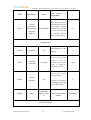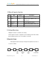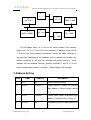
1
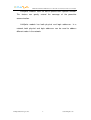
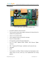
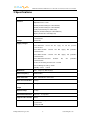
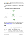
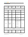
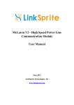
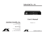
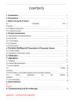
UART/RS232/RS485/USB/Ethernet
Over Powerline Communication
Transceiver Module
User Manual
.
LinkSprite Technologies, Inc
January, 2009
www.linksprite.com
UART/ RS232/RS485/USB/Ethetnet Over Powerline Communication Transceiver Module
Table of Content
Ⅰ Summary ..................................................................................................................3
1 Introduction............................................................................................................................3
2 Features ..................................................................................................................................5
3 Specifications .........................................................................................................................6
4 Applications ...........................................................................................................................7
Ⅱ Diagram....................................................................................................................8
1 Functional Diagram................................................................................................................8
2 Board Layout..........................................................................................................................8
3 Switch Description ...............................................................................................................9
4 LED........................................................................................................................................9
5 Definition of Pin...................................................................................................................10
6 Interface Card Socket Definition and Layout………………………………………………11
Ⅲ Command Interface................................................................................................13
1 Command Mode...................................................................................................................13
1.1 Enter command mode ...............................................................................................13
1.2 Exit command mode .................................................................................................13
2 Arguments and Responses ...................................................................................................13
2.1 Arguments and Responses ........................................................................................13
2.2 Commands without Arguments.................................................................................13
2.3 Modified arguments ..................................................................................................14
3 Command List......................................................................................................................15
Ⅳ Repeater Function ..................................................................................................18
1 Introduction..........................................................................................................................18
2 Function Setting ...................................................................................................................19
2.1Start repeater function ................................................................................................19
2.2Turn off repeater function ..........................................................................................19
2.3 Setting Illustration.....................................................................................................20
3 Repeater Grade.....................................................................................................................20
Ⅴ Logic Address ........................................................................................................21
1 Logic Address ......................................................................................................................21
2 Address Setting ....................................................................................................................22
Ⅵ Application Illustration ..........................................................................................25
LinkSpriteTechnologies, Inc.
2
www.linksprite.com
UART/ RS232/RS485/USB/Ethetnet Over Powerline Communication Transceiver Module
Ⅰ Summary
1. Introduction
This document documents LinkSprite second-generation powerline
communication modem. Based on the feedbacks of the first-generation,
LinkSprite second-generation powerline communication modem products
are consisted of a PLC-UART motherboard, UART-RS232 daughter board,
UART-RS485
daughter
board,
UART-USB
daughter
board,
and
UART-Ethernet daughter board.
On the PLC-UART motherboard, there is a 20-pin receptacle, users
can choose different daughter boards based on the interface needs. This
20-pin receptacle is pin-compatible with Xbee module from Digi
(www.digi.com). So a Xbee module can also be used on PLC-UART, and
PLC-UART will become a powerline communication to Zigbee bridge.
The new generation PLC-UART motherboard also support DIP by
optional pins that can be used to directly plug to user’s board without doing
screwing. The interface board signals such as RS232/RS485/USB signals
are also routed back to motherboard through the 20-pin receptacle, and
again to users’ board through these DIP pins.
Powerline communication transceiver modules from LinkSprite
(LinkSprite modules) are transceiver modules designed to send/receiver
serial data over the powerline network. PLC-UART is designed to
transparently move serial data over the powerline network, and achieves
the target of replacing cables by the ubiquitous powerline network.
LinkSpriteTechnologies, Inc.
3
www.linksprite.com
UART/ RS232/RS485/USB/Ethetnet Over Powerline Communication Transceiver Module
LinkSprite modules have the built-in packet-level repeater function.
This feature can greatly extend the coverage of the powerline
communication.
LinkSprite module has both physical and logic addresses. In a
network, both physical and logic addresses can be used to address
different nodes in the network.
LinkSpriteTechnologies, Inc.
4
www.linksprite.com
UART/ RS232/RS485/USB/Ethetnet Over Powerline Communication Transceiver Module
2 Features
A PLC-UART with a UART-RS232 daughter card
•
AC and DC powerline Communications
•
Fully transparent mode, plug and play coming out of the box without the
need to do any programming.
•
Built-in error correction codes.
•
Built-in repeater function to extend the coverage.
•
Physical and logic address
•
AT commands used for advanced configuration.
•
3.3V TTL UART, Optional RS232, RS485. USB, Ethernet, Zigbee
interfaces
•
FSK(Frequency Shift Keying)modulation used in physical layer
•
Low power
•
RoHS
•
Small module size (55mm X 85mm including the on-board power switch
regular keep out area), and easy to be implemented into existing
products.
LinkSpriteTechnologies, Inc.
5
www.linksprite.com
UART/ RS232/RS485/USB/Ethetnet Over Powerline Communication Transceiver Module
3 Specifications
Product name
PLC-UART Transceiver Module
Interface
3.3V TTL UART
Optional interface cards:
RS232 (model/ordering no: UART-RS232)
RS485 (model/ordering no: UART-RS485)
USB (model/ordering no: UART-USB)
Ethernet (model/ordering no: UART-Ethernet)
Zigbee (model: Xbee from Digi.com)
Communication
Line
230VAC/50Hz
110VAC/60Hz
Voltage
0-400V DC
Supply Voltages
Three different models:
PLC-UART-24V: external 24V DC supply, AC and DC powerline
communications
PLC-UART-12V-DC:
external
12V
DC
supply,
DC
powerline
external
12V
DC
supply,
AC
powerline
communication
PLC-UART-12V-AC:
communication
PLC-UART-220V:on-board
80-250V
AC,
AC
powerline
communication
Peak Current During Transmission < 100mA
Current During Receiving < 50mA
Standby current
< 30mA
(Frequency Shift Keying)
Modulation
FSK
Carrier frequency
262K/144KHz
Error Correction
FEC Forward Error Correction
Data rate on Powerline
30Kbps
Maximum packet data
300bytes
(
)
length
Repeater Hops
3 Hops
Transmission distance
300 feets
Support nodes number
65535
LED
Power Line Activity
(no repeater)
LED
system LED
serial port LED
LinkSpriteTechnologies, Inc.
6
www.linksprite.com
UART/ RS232/RS485/USB/Ethetnet Over Powerline Communication Transceiver Module
4 Applications
•
AMR
•
Industry manufacture and control
•
Safeguard, fire alarm, smoke alarm
•
Collect and transmit instrument data
•
Safeguard and monitor
•
Home automation
•
Solar/Wind electricity generation system
LinkSpriteTechnologies, Inc.
7
www.linksprite.com
UART/ RS232/RS485/USB/Ethetnet Over Powerline Communication Transceiver Module
Ⅱ Diagram
1 Functional Diagram
Power
lines
Carrier
signal
Power
lines
Coupling
circuit
Power
lines
carrier
module
UART 20-pin
socket
Serial data
2 Board Layout
LinkSpriteTechnologies, Inc.
8
www.linksprite.com
UART/ RS232/RS485/USB/Ethetnet Over Powerline Communication Transceiver Module
3 Switch Description
A switch is used to control the operation mode for 24V external DC supply
model:
For AC input to J2 as power supply and communication line:
For DC input to J2 as power supply and communication line:
For DC as power supply to J8, and DC or AC as communication line
connected to J2:
The factory setting will be programmed as the model you ordered. Please
contact [email protected] if you are not sure what you are doing.
4 LED
PLC LED
PLC LED: green mans module is sending data to PLC; red
means module is receiving data from PLC
RDY_LED
System LED,green means system is in normal
LED1
Serial port LED,green means module is receiving data from
aerial port; red means module is sending data to serial port
LinkSpriteTechnologies, Inc.
9
www.linksprite.com
UART/ RS232/RS485/USB/Ethetnet Over Powerline Communication Transceiver Module
5 Definition of DIP Pins
LinkSpriteTechnologies, Inc.
10
www.linksprite.com
UART/ RS232/RS485/USB/Ethetnet Over Powerline Communication Transceiver Module
6 Interface Card Socket Definition and Layout
The pin layout of interface cards is compatible with Xbee module from Digi
(www.digi.com). The socket on the PLC-UART motherboard can be used to
receive any interface card with the pin out shown below:
Pin assignment of the interface card socket:
Pin #
Name
Direction
Description
1
VCC
-
3.3V Power supply
2
DOUT
Output
UART Data Out
3
DIN
Input
UART Data In
4
EX4
Depending on
Route daughtercard
model of daughter
final interface signal
card
back to mother board,
and to the DIP pins to
user’s board
5
RESET
Input
Module Reset
6
EX3
Depending on
Route daughtercard
model of daughter
final interface signal
card
back to mother board,
and to the DIP pins to
user’s board
7
EX2
Depending on
Route daughtercard
model of daughter
final interface signal
card
back to mother board,
and to the DIP pins to
user’s board
8
LinkSpriteTechnologies, Inc.
EX1
11
Depending on
Route daughtercard
model of daughter
final interface signal
www.linksprite.com
UART/ RS232/RS485/USB/Ethetnet Over Powerline Communication Transceiver Module
card
back to mother board,
and to the DIP pins to
user’s board
9
SLEEP
Input
Pin Sleep Control Line
10
GND
-
Ground
11
Unused
-
-
12
Unused
-
-
13
Unused
-
-
14
Unused
-
-
15
Associate
Output
Associated Indicator
16
Unused
-
-
17
Unused
-
-
18
Unused
-
-
19
Unused
-
-
20
Unused
-
-
LinkSpriteTechnologies, Inc.
12
www.linksprite.com
UART/ RS232/RS485/USB/Ethetnet Over Powerline Communication Transceiver Module
Ⅲ Command Interface
1 Command Mode
1.1 Enter command mode
The module can be put into command mode by sending “+++” through
serial port. The module will respond with an “ok”. In order to prevent the
situation where the user data” +++”mistakenly triggers the command mode,
there must be no serial port data input one second before and after the
receiving of "+++". At the same time, the gap between the three”+” should
not be more than one second, otherwise, it will be considered as a data
rather than a command.
1.2 Exit command mode
There are two approaches to exit command mode. One way is to input
command “ATEX”. The other is to timeout and automatically exit. In either
case, the modules will response "exited". The timeout value can be set by
command "ATTO"
2 Arguments and Responses
2.1 Arguments and Responses
For all the commands with arguments: if the parameters are correct,
the module will respond with an “ok”. Otherwise, the modules will response
with an “invalid para”. If there are no arguments associated with the
commands, it will be treated as polling modem and the module will
respond with the existing arguments residing in the module.
LinkSpriteTechnologies, Inc.
13
www.linksprite.com
UART/ RS232/RS485/USB/Ethetnet Over Powerline Communication Transceiver Module
2.2 Commands without Arguments
There are four commands without arguments.
● + + +: enter command mode; will directly return “ok”.
● ATEX: exit the command mode, return “exited”.
● ATRS: software reset, will reset the module immediately, no return.
● ATSR: in search for other modules on the power lines, this will return the
name of the found module. Please wait for two seconds after sending a
command. The name of module received in two seconds will be shown in
the serial port, otherwise, the name received after two seconds will be
ignored. Note: In the course of searching, all bytes input from serial port
also will also be ignored.
2.3 Modified arguments
Except for serial arguments, the modified arguments will be
immediately saved into eeprom and take effect. The serial arguments
won’t take effect immediately after being modified to avoid user from
modifying PC serial arguments before inputting command. Serial
arguments will take effect through automatically resetting module when
exiting the command mode.
LinkSpriteTechnologies, Inc.
14
www.linksprite.com
UART/ RS232/RS485/USB/Ethetnet Over Powerline Communication Transceiver Module
3 Command List
Command
Description
Arguments
Description
Default
Control Class
+++
ATEX
Exit
none
Enter command mode
none
Exit command mode
Timeout value,
ATTO
Time out
1-30
5
unit: second
ATRS
Reset
none
Software reset
This controls if the
following setting will be
saved to flash:
Save to flash
ATWT
memory
Y,N
control
ATDA
ATNA
ATDT
ATRT
ATWT
itself
N
is
not
saved to flash.
Network class
ATDA
Domain
Address
LinkSpriteTechnologies, Inc.
1-32767
15
Domain
Address
Logic Address
of
1
www.linksprite.com
UART/ RS232/RS485/USB/Ethetnet Over Powerline Communication Transceiver Module
ATNA
Node Address
1-65535
Node
Address
of
logical address
1
When set to 0, the packet
Packet
will be broadcasted in the
Destination
ATDT
Serial Number
same
0-2147483646
logical
domain.
Otherwise, the packet will
(Physical
be sent to the node with
Address)
the
specified
0
physical
address (serial number).
Function class
ATRP
Repeater
Y,N
Relay function, Y is on,
N for off
Y
When the received signal
ATRT
Repeater
Threshold
strength
0- 32708
is
below
this
threshold and the repeater
function
is
enabled,
1023
the
packet will be repeated.
Turn
on
the
repeater
function remotely.
ATRR
Remote
Repeater
Y,N
It may be set broadcast
Y
or individually depending
on the ATDT settings.
A string with
ATNM
Name
length less than
Set the name of the
15
module
PU-R485A
Communication class
LinkSpriteTechnologies, Inc.
16
www.linksprite.com
UART/ RS232/RS485/USB/Ethetnet Over Powerline Communication Transceiver Module
ATBD
Baud Rate
ATDB
Data Bit
1200, 2400, 4800,
9600, 19200
5,6,7,8
Baud Rate
9600
Data bit
8
Parity bit
ATPA
Parity
,N = no, O = odd
N, O, E
N
, E = even
ATST
Stop Bit
1,2
Stop bit
1
Debug class
The raw data for
debugging. The
module will output sent
raw packets from host
ATRW
Raw
Y,N
to the module, and not
N
just the payload. Y
means turn on this
function, N means
turning off.
Search for peer
ATSR
Search
none
module on the power
line network
LinkSpriteTechnologies, Inc.
17
www.linksprite.com
UART/ RS232/RS485/USB/Ethetnet Over Powerline Communication Transceiver Module
Ⅳ Repeater Function
1 Introduction
To extend the coverage, Linksprite modules have built-in repeater
function.
When the module's repeater function is turned on (off is the default
setting), the module echos the data packet from the power line, while
entertaining the data sent by host through the serial port.
A
C
Because of far distance, data transmission can not be
reached.
A
B
C
After adding repeater function to proper locations, the data
can be transmitted farther.
Transceiver function is not influenced by repeater function, that is to
say, each module can be used as a separate repeater or can be seen as
repeater when sending and receiving data. It can not only send and
receive data from the power line, but also repeat other data packets.
In order to prevent network congestion, the module is smart smart
enough to know the data were sent or repeated by itself and will discard
LinkSpriteTechnologies, Inc.
18
www.linksprite.com
UART/ RS232/RS485/USB/Ethetnet Over Powerline Communication Transceiver Module
the data packets when receiving the duplicated ones.
Note: Due to the fact that repeaters will resent the received data
packets, if the number of repeater is too large, a number of repeaters will
seize the channel, and lead to increased communication time. When
deploying the repeater, one should take full account of the balance of
reliability and real-time.
2 Function Setting
AT command ‘ATRP’ is designed to set up the repeater function.
2.1Turn on repeater function
Steps
input
response
description
1
+++
ok
Enter command mode
2
ATRP
Y or N
Poll current repeater status, Y is on,
N for off
3
ATRP Y
ok
Turn on repeater function
4
ATRP
Y
Check present repeat status, ON
5
ATEX
exit
Exit command mode
LinkSpriteTechnologies, Inc.
19
www.linksprite.com
UART/ RS232/RS485/USB/Ethetnet Over Powerline Communication Transceiver Module
2.2Turn off repeater function
steps
input
response
description
1
+++
ok
Enter command mode
2
ATRP
Y or N
Check current repeater status, Y is
on, N for off
3
ATRP N
ok
Turn off repeater function
4
ATRP
N
Check current repeater status, OFF
5
ATEX
exit
Exit command mode
2.3 Setting Illustration
●Repeater function is available in the factory.
●Once repeater function is modified; it will immediately take effect and be
preserved permanently, even if the module is restarted.
3 Repeater Hops
A data packet could at most pass through third repeater three times. It
is shown as follows:
A
B
C
The
first
time
LinkSpriteTechnologies, Inc.
D
The
second
time
20
E
The
third
time
F
No
re-transition
www.linksprite.com
UART/ RS232/RS485/USB/Ethetnet Over Powerline Communication Transceiver Module
Data packet is sent from module A to module B. From module B to
module C is the first time, to module D is the second time, and to module E
is the third time. Module F is the termination. Therefore, data packet won’t
be sent to module F.
LinkSpriteTechnologies, Inc.
21
www.linksprite.com
UART/ RS232/RS485/USB/Ethetnet Over Powerline Communication Transceiver Module
Ⅴ Logic Address
1 Logic Address
Module data packets are transmitted in the way of broadcasting in
power lines. All modules will receive the data packets issued by the
module and sent them, through the serial port under carrier signals area.
When multiple modules are installed on the same power line network,
however, one does not want them to communicate directly; thus, the
networks can be addressed by the logic address.
Logic address is composed of two parts: domain and nodes. For
example, the logic address (10:200) means that the domain value is 10,
node value is 200. Logic address is the default setting (1:1).
Module data packets can only be received and processed by the
module at the same domain. Other modules, even detecting the carrier
signal will not receive, nor to transmit to the serial port or repeater.
LinkSpriteTechnologies, Inc.
22
www.linksprite.com
UART/ RS232/RS485/USB/Ethetnet Over Powerline Communication Transceiver Module
A
1:1
B
10:8
H
10:8787
F
10:59
G
2002:65500
E
1:299
C
2002:1998
D
10:1000
On the above figure, A, E are at the same network, their domain
values are 1; B, D, F, H are at the same network, its domain values are10;
C, G are at the same network, their domain values are 2002. Although in
the physically speaking, all the modules are in a power line network, the
packet issued by A, will only be received and processed by E, other
modules will not respond. Similarly, packet issued by F, only B, D, H will
receive and process packet issued by F, other modules will not work.
2 Address Setting
step
input
response
description
1
+++
ok
Enter command mode
2
ATDA
1-32767
Check domain values of present
logic address. Default factory setting
is 1.
3
ATNA
1-65535
Check nodes values of present logic
address. Default factory setting is 1.
4
ATDA 2
ok
Set domain value of logic address as
2
LinkSpriteTechnologies, Inc.
23
www.linksprite.com
UART/ RS232/RS485/USB/Ethetnet Over Powerline Communication Transceiver Module
5
ATNA 45
ok
Set nodes of logic address as 45
6
ATDA
2
Check
domain
values
of
logic
address
7
ATNA
45
Check node values of logic address
8
ATEX
exited
Exit command mode
LinkSpriteTechnologies, Inc.
24
www.linksprite.com
UART/ RS232/RS485/USB/Ethetnet Over Powerline Communication Transceiver Module
Ⅵ Application Illustration
Intelligent instruments widely adopt RS485 bus to communicate. For
example, the power meter automatic meter reading systems, data
concentrator through the RS485 bus read the message from power meter.
RS485
A B
Power
Meter
Power
Meter
Power
Meter
Power
Meter
Power
Meter
Power
Meter
Data
concentrator
In order to automatically meter reading, RS485 bus needs to be
deployed. Here, using PLC-UART module, one can use the existed power
lines to directly complete data transmission.
LinkSpriteTechnologies, Inc.
25
www.linksprite.com
UART/ RS232/RS485/USB/Ethetnet Over Powerline Communication Transceiver Module
Power lines
Power
meter
Power
meter
Power
meter
PLC-U
ART
PLC-U
ART
PLC-U
ART
PLC-U
ART
Power
meter
PLC-U
ART
Power
meter
PLC-U
ART
Power
meter
PLC-UART
Data
concentrator
LinkSpriteTechnologies, Inc.
26
www.linksprite.com
UART/ RS232/RS485/USB/Ethetnet Over Powerline Communication Transceiver Module
LinkSprite Technolgies, Inc.
1410 Cannon Mountain Dr.
Longmont, CO 80503
(Voice) 720-9494-932
(Email) [email protected]
http://www.linksprite.com
LinkSpriteTechnologies, Inc.
27
www.linksprite.com