1
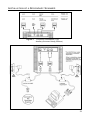
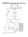
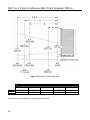
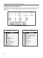
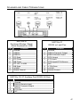
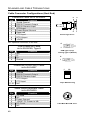
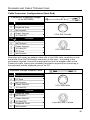
METROLOGIC INSTRUMENTS, INC.
MS7320 InVista® Series
Installation and User’s Guide
Copyright
© 2008 by Metrologic Instruments, Inc. All rights reserved. No part of this
work may be reproduced, transmitted, or stored in any form or by any means
without prior written consent, except by reviewer, who may quote brief
passages in a review, or provided for in the Copyright Act of 1976.
Trademarks
Metrologic is a registered trademark of Metrologic Instruments, Inc.
Products identified in this document are hereby acknowledged as
trademarks, registered or otherwise, of Metrologic Instruments, Inc. or their
respective companies.
TABLE OF CONTENTS
Introduction........................................................................................................... 1
Scanner and Accessories..................................................................................... 2
Installation
For OCIA Interface............................................................................................ 4
For Keyboard Wedge Interface......................................................................... 5
For Stand-Alone Keyboard Interface ................................................................ 6
For USB Interface ............................................................................................. 7
For RS232 or Light Pen Interfaces ................................................................... 8
For IBM 46xx Interface ................................................................................... 10
Of a Secondary Scanner................................................................................. 11
Scanner Parts..................................................................................................... 14
Maintenance....................................................................................................... 14
Cable Cover Installation and Removal ............................................................... 15
Face Plate Removal ........................................................................................... 15
Scanner Labels .................................................................................................. 16
Indicators
Audible............................................................................................................ 17
Visual.............................................................................................................. 18
Failure Mode................................................................................................... 19
Power Save Modes and the Multi-Function Button............................................. 20
Scan Volume ...................................................................................................... 22
Depth of Field by Minimum Bar Code Element Width......................................... 23
Flex Stand Installation ........................................................................................ 25
EAS Deactivation Antenna ................................................................................. 28
Troubleshooting Guide ....................................................................................... 29
Design Specifications ......................................................................................... 34
RS232 Demonstration Program.......................................................................... 36
Applications and Protocols ................................................................................. 37
Configuration Modes .......................................................................................... 38
Upgrading the Firmware ..................................................................................... 39
ii
TABLE OF CONTENTS
Default Settings .................................................................................................. 40
Scanner and Cable Terminations
Scanner Pinout Connections .......................................................................... 46
Cable Connector Configurations (Host End)................................................... 48
Limited Warranty ................................................................................................ 50
Regulatory Compliance
Safety ............................................................................................................. 51
EMC................................................................................................................ 52
Patents ............................................................................................................... 55
Index................................................................................................................... 56
Contact Information And Office Locations .......................................................... 58
iii
INTRODUCTION
The MS7320 InVista® offers an outstanding combination of features, versatility,
performance, and durability. This fixed mount laser bar code scanner provides
ease of use and high throughput speeds by featuring a large, dynamic, and
aggressive scan volume. Firmware updates are easily loaded into Flash
memory.
The MS7320 is equipped with a multitude of standard features including:
•
Automatic Scanning Operation
•
EAS Deactivation Antenna
•
A Configurable Depth of Field
•
Supports Multiple Interfaces Including USB and Keyboard Wedge
•
Custom Edit the Bar Code Data
•
OPOS and JPOS System Compatible
•
RS232 Auxiliary Port for Adding Peripherals
•
PowerLink, User Replaceable Cables
•
Field Replaceable Outer Window
•
Sunrise 2005 Compliant
SCANNER
INTERFACE
MS7320-13
RS232, IBM 46xx, OCIA, Aux
MS7320-37
RS232, Light Pen, Keyboard Wedge, Stand-Alone
Keyboard, USB, Aux
1
SCANNER AND ACCESSORIES
B ASIC K IT
Part #
Description
MS7320
InVista Series Scanner
00-02407
MetroSelect® Configuration Guide
00-02896
MS7320 InVista Series Installation and User’s Guide
52-52511
24" EAS Cable
Guides also available for download at www.metrologic.com.
O PTIONAL A CCESSORIES
Part #
59-59xxx*
Description
Straight PowerLink Cable with built in power jack.
2.1 m (7') cord with short strain relief
xxx* specifies connection to the host.
Contact a customer service representative for additional information.
59-59002
MVC**
**
2
Keyboard Wedge PowerLink Cable with Adapter Cable
Metrologic Voltage Converter Cable,
±12VDC to +5.2VDC
Contact a Metrologic Customer Service representative for additional
information on Metrologic’s MVC cable series and the host connections
available.
59-59020
Stand Alone Keyboard Wedge PowerLink Cable
59-59165
USB PowerLink Cable (Type A)
54-54667
RS232 AUX PowerLink Cable
SCANNER AND ACCESSORIES
O PTIONAL A CCESSORIES
Part #
Description
AC to DC Power Transformer - Regulated 5.2V@ 1A output
46-46759
120V United States
46-46616
220V – 240V Continental European
46-46615
220V – 240V United Kingdom
46-46984
220V – 240V China
46-46985
220V – 240V Australia
46-00174
3" Flex Stand
46-00157
6" Flex Stand
46-00175
12" Flex Stand
R EPLACEMENT P ARTS
Part #
Description
46-46925
Standard Red Window Face Plate
46-46852
Pedestal Base
For use with 46-00174, 46-00175, and 46-00157 flex stands.
Other items may be ordered for the specific protocol being used. To order
additional items, contact the dealer, distributor or call Metrologic’s Customer
Service Department at 1-800-ID-METRO or 1-800-436-3876.
3
INSTALLATION FOR OCIA INTERFACE
1.
Turn off the host system.
2.
Connect the MVC cable to
the 10-pin OCIA interface jack. It is
the 2nd round opening from the left
side of the MS7320 (see figure 1).
3.
Connect the other end of the MVC
cable to the host.
Before continuing verify that the MVC
cable is connected to the appropriate
interface jack on the scanner. An
incorrect cable connection can cause
communication problems or potential
damage to the scanner.
Plugging the scanner into the
serial port of the PC does not
guarantee that scanned
information will appear at the
PC. A software driver and
correct configuration settings are
also required for proper
communication.
4.
Turn on the host system.
5.
Scan the Load OCIA Defaults bar
code to configure the MS7320 for
OCIA communication.
6.
Figure 1: OCIA, Interface
Load OCIA Defaults
Snap on the cable cover.
³
9
9
9
9
9
For additional communication options for OCIA interfaces refer to the
MetroSelect Configuration Guide (MLPN 00-02407).
See SELV Power Source caution statement located on page 16 of this manual.
4
3
INSTALLATION FOR KEYBOARD WEDGE INTERFACE
1.
Turn off the host system.
2.
Disconnect the keyboard from the host.
3.
Connect the PowerLink cable to the 10-pin
nd
KBW interface jack. It is the 2 round
opening from the left side of the MS7320
(see figure 2).
4.
Connect the “Y” end of the
PowerLink cable to the keyboard
and the keyboard port on the host.
If necessary use the male/female
adapter cable supplied with the scanner for
proper connections.
Before continuing verify that the
PowerLink cable is connected to the
appropriate interface jack on the scanner.
An incorrect cable connection can cause
communication problems or potential
damage to the scanner.
5.
Connect the external power supply
to the power jack on the PowerLink cable.
6.
Check the AC input requirements
of the power supply to make sure
the voltage matches the AC outlet.
7.
Connect AC power to the transformer.
The outlet should be near the equipment
and easily accessible.
8.
Scan the Load Keyboard Wedge Defaults
bar code to configure the MS7320 for
Keyboard Wedge communication.
9.
Turn on the host system.
10. Snap on the cable cover.
Figure 2: Keyboard Wedge Interfaces
Load Keyboard
Wedge Defaults
³
9
9
9
9
9
4
See SELV Power Source caution statement located on page 16 of this manual.
5
INSTALLATION FOR STAND-ALONE KEYBOARD INTERFACE
1.
Turn off the host system.
2.
Disconnect the keyboard from the host.
3.
Connect the PowerLink cable to the 10-pin
Stand-Alone Keyboard interface jack. It is
the 2nd round opening from the left side of
the MS7320 (see figure 3).
4.
Connect the other end of the PowerLink
cable to the keyboard port on the host.
Before continuing verify that the
PowerLink cable is connected to the
appropriate interface jack on the scanner.
An incorrect cable connection can cause
communication problems or potential
damage to the scanner.
5.
Connect the external power supply to the
power jack on the PowerLink cable.
6.
Check the AC input requirements of the
power supply to make sure the voltage
matches the AC outlet.
7.
Connect AC power to the transformer.
The outlet should be near the equipment
and easily accessible.
8.
Figure 3: Stand-Alone Keyboard
Interface
Load Keyboard
Wedge Defaults
Scan 1
St
³
Scan the two bar codes in numbered
sequence in order to configure the
MS7320 for Stand-Alone Keyboard
communication.
Note:
When scanning the bar codes, cover the
code not being scanned to ensure the
codes are read in the proper sequence.
9.
Turn on the host system.
10. Snap on the cable cover.
9
9
9
9
4
Enable Stand-Alone
Keyboard Wedge
Scan 2
nd
³
5
1
5
5
See SELV Power Source caution statement located on page 16 of this manual.
6
9
1
5
3
INSTALLATION FOR USB INTERFACE
1.
Turn off the host system.
2.
Determine if your application requires USB
Keyboard communication protocols or
USB Point-of-Sale communication
protocols.
3.
If you require USB Keyboard
communication protocols, skip to step 4.
If you require USB Point-of-Sale
communication protocols set the dip
switches shown in figure 4a to positions
1 and 2.
4.
Connect the PowerLink cable to the 10-pin
nd
USB interface jack. It is the 2 round
opening from the left side of the MS7320
(see figure 4b).
5.
Connect the other end of the USB cable to
the host.
Figure 4a: POS Dip Switch
Before continuing verify that the USB
cable is connected to the appropriate
interface jack on the scanner. An incorrect
cable connection can cause
communication problems or potential
damage to the scanner.
Plugging the scanner into the USB
port of the PC does not guarantee
that scanned information will appear
at the PC. A software driver and
correct configuration setting are also
required for proper communication.
6.
Scan the Enable USB Defaults bar code to
configure the MS7320 for USB
communication.
7.
Turn on the host system.
8.
Snap on the cable cover.
Figure 4b: USB, Interface
Enable USB Defaults
³
9
9
9
9
7
8
See SELV Power Source caution statement located on page 16 of this manual.
7
INSTALLATION FOR RS232 OR LIGHT PEN INTERFACES
1.
Turn off the host system.
2.
Connect the PowerLink cable to the
10-pin RS232/Light Pen interface
jack. It is the 1st round opening from
the left side of the MS7320
(see figure 5).
3.
Connect the other end of the
PowerLink cable to the host.
Before continuing verify that the
PowerLink cable is connected to the
appropriate interface jack on the
scanner. An incorrect cable connection
can cause communication problems or
potential damage to the scanner.
4.
Connect the external power supply to
the power jack on the PowerLink
Cable.
5.
Check the AC input requirements of
the power supply to make sure the
voltage matches the AC outlet.
6.
Connect AC power to the
transformer. The outlet should be
near the equipment and easily
accessible.
7.
Scan the appropriate bar codes on
page 9 to configure the MS7320 for
RS232 or Light Pen communication.
8.
Turn on the host system.
9.
Snap on the cable cover.
Figure 5: RS232 or
Light Pen Interface
See SELV Power Source caution statement located on page 16 of this manual.
8
INSTALLATION FOR RS232 OR LIGHT PEN INTERFACES
Codes needed for Step 7 on page 8.
For RS232 Communication:
Recall Defaults
Scan 1st
³
9
9
9
9
9
8
Enable RS-232
Scan 2nd
³
4
1
5
5
5
4
For Light Pen Communication:
Recall Defaults
Scan 1st
³
9
9
9
9
9
8
Enable Light Pen/Wand
Scan 2nd
³
4
1
5
5
2
4
9
INSTALLATION FOR IBM 46XX INTERFACE
1.
Turn off the host system.
2.
Connect the MVC cable to the 10-pin
IBM 46xx interface jack. It is the
1st round opening from the left side of
the MS7320 (see figure 6).
3.
Connect the other end of the MVC
cable to the host.
Before continuing verify that the MVC
cable is connected to the proper
communication jack on the scanner.
Incorrect cable connection can cause
communication problems or potential
damage to the scanner.
Plugging the scanner into the
serial port of the PC does not
guarantee that scanned
information will appear at the
PC. A software driver and
correct configuration setting are
also required for proper
communication to occur.
4.
Turn on the host system.
5.
Scan the Load 46xx IBM Defaults bar
code to configure the MS7320 for
RS232/IBM communication.
6.
Snap on the cable cover
Figure 6: IBM 46xx Interface
Load 46xx IBM Defaults
For additional communication
options for IBM interfaces refer to the
MetroSelect Configuration Guide
(MLPN 00-02407).
³
9
9
9
9
9
See SELV Power Source caution statement located on page 16 of this manual.
10
5
INSTALLATION OF A SECONDARY SCANNER
1.
Turn off the host system.
2.
Connect the round end of the PowerLink RS232 AUX cable
[ MLPN 54-54667 ] to the RS232 jack of the auxiliary scanner (see figure 7).
3.
Connect the other end of the PowerLink RS232 AUX cable into the 1st jack
from the left side of the MS7320. The Aux jack has a square opening.
The following Metrologic scanners can be used in the “Aux” input of the
MS7320: the MS9520, MS9540, MS6220, MS7120, MS6520, MS6720,
MS7220 or another MS7320.
Important: The MS7320 aux port requires the signals: transmit, receive,
RTS & CTS from the auxiliary scanner.
4.
Connect the MS7320/Host PowerLink* cable to the appropriate interface jack
on the back of the MS7320.
5.
Connect the other end of the MS7320/Host PowerLink cable to the Host.
6.
Connect the external power supplies for the auxiliary scanner and the
MS7320 to the power jacks on the two PowerLink cables.
Before continuing verify that the PowerLink cables are connected to the
appropriate interface jacks on the scanner. An incorrect cable
connection can cause communication problems or potential damage to
the scanner.
7.
Check the AC input requirements of both power supplies to make sure the
voltage matches the AC outlets.
8.
Snap on the cable cover.
9.
Connect AC power to the transformers. The outlets should be near the
equipment and easily accessible.
10. Configure the MS7320 for the appropriate interface configuration settings.*
Continued on page 12.
* The MS7320/host cable connection is interface dependent. Refer to the
installation steps provided for the type of interface (RS232, IBM 46xx, etc.)
required for your application.
See SELV Power Source caution statement located on page 16 of this manual.
11
INSTALLATION OF A SECONDARY SCANNER
11. Scan the following bar code to configure the auxiliary port on the MS7320 to
accept a Metrologic scanner as the secondary scanner.
The following bar codes do not apply when using an MS6720 as a
secondary scanner. Contact a Metrologic representative for additional
information on the MS6720. If the secondary scanner is not a
Metrologic scanner refer to Section O of the MetroSelect
Configuration Guide.
Enable Aux Port
³
4
3
7
3
3
0
The auxiliary input port’s data format must match the main output
format of the secondary scanner.
12. Scan the following bar codes, in order, to configure the secondary scanner to
match the auxiliary port’s data format.
1st
2nd
Enable AUX Output
Secondary Scanner Data
Format
³
1
2
4
8
1
7
4
3
7
5
3
0
3rd
4th (Optional)
Enable Comm Timeouts
Turn OFF Secondary
Scanner’s Beeper
³
1
1
8
4
1
2
13. Turn on the host system.
12
³
³
3
1
8
5
0
5
INSTALLATION OF A SECONDARY SCANNER
Figure 7:
Connector Orientation (Top)
Auxiliary Scanner Setup (Bottom)
13
SCANNER PARTS
Figure 8: Scanner Parts
Output Window (Laser Aperture)
Speaker
Replaceable Window Face Plate
Red LED (Top LED)
Green LED (Bottom LED)
Multi-Function Button (see page 21)
Cable Connection and Dip Switch Area
Cable Cover
Pedestal Base/Stand Foot
MAINTENANCE
Smudges and dirt on the unit’s window can interfere with the unit’s performance.
If the glass window requires cleaning, use only a mild glass cleaner containing no
ammonia. When cleaning the window, spray the cleaner onto a lint free, nonabrasive cleaning cloth then gently wipe the window clean. If the red window
requires cleaning use mild soap and water with a lint free, non-abrasive cleaning
cloth then gently wipe the window clean.
If the unit’s case requires cleaning, use a mild cleaning agent that does not
contain strong oxidizing chemicals. Strong cleaning agents may discolor or
damage the unit’s exterior.
14
CABLE COVER INSTALLATION AND REMOVAL
Figure 9:
Installing the Cable Cover (left).
Removing the Cable Cover
(bottom right).
FACE PLATE REMOVAL
Figure 10: Face Plate Removal
15
SCANNER LABELS
The MS7320 has 2 labels on the back of the unit. These labels contain the
model number, date of manufacture, serial number, and caution information. An
additional caution label is located under the window faceplate and a label noting
the jack interfaces is located under the connector cover. The following are
examples of these labels.
Figure 11: Scanner Labels
To maintain compliance with applicable standards, all circuits connected to the
scanner must meet the requirements for SELV (Safety Extra Low Voltage) according
to EN/IEC 60950-1.
To maintain compliance with standard CSA C22.2 No. 60950-1/UL 60950-1 and norm
EN/IEC 60950-1, the power source should meet applicable performance requirements
for a limited power source.
16
AUDIBLE INDICATORS
When the MS7320 scanner is in operation, it provides audible feedback. These
sounds indicate the status of the scanner. Eight settings are available for the
tone of the beep (normal, 6 alternate tones and no tone). To change the tone,
use the Multi-Function Button or refer to the MetroSelect Configuration Guide.
One Beep
When the scanner first receives power, the green LED will turn on,
the red LED will flash and the scanner will beep once. The red LED
will remain on for the duration of the beep. The scanner is now
ready to scan.
When the scanner successfully reads a bar code, the red LED will
flash and the scanner will beep once (if configured to do so). If the
scanner does not beep once and the red light does not flash, then
the bar code has not been successfully read.
Razzberry Tone
This is a failure indicator. Refer to failure modes on page 19.
Three Beeps - during operation
When placing the scanner in program mode, the red LED will flash
while the scanner simultaneously beeps three times. The red and
green LEDs will continue to flash until the unit exits program mode.
Upon exiting program mode, the scanner will beep three times and
the red LED will stop flashing.
When configured, three beeps can also indicate a communications
timeout during normal scanning mode.
When using one-code-configuring, the scanner will beep three
times (the current selected tone), followed by a short pause, a high
tone and a low tone. This tells the user that the single configuration
bar code has successfully configured the scanner.
Three beeps will also occur during a manual adjustment of the
beeper tone. With each short depression of the Multi-Function
Button, the new tone will be heard, followed by a short pause then
two more of the new current tones.
Three Beeps - on power up
This is a failure indicator. Refer to failure modes on page 19.
17
VISUAL INDICATORS
There is a red LED and green LED on
the front of the MS7320. When the scanner is on, the
flashing or constant illumination of the LEDs indicates
the status of the current scan and the scanner.
Figure 12: LEDs
No Red or Green LED
The LEDs will not be illuminated if the scanner is not receiving
power from the host or transformer.
Steady Green
When the laser is active, the green LED is illuminated. The
green LED will remain illuminated until the laser is deactivated.
During the power save mode, the laser will turn on and off.
During this period, the green LED remains illuminated.
Steady Green and Single Red Flash
When the scanner successfully reads a bar code, the red LED
will flash and the scanner will beep once. If the red LED does
not flash or the scanner does not beep once, then the bar code
has not been successfully read.
Steady Green and Steady Red
After a successful scan, the scanner transmits the data to the
host device. Some communication modes require that the host
inform the scanner when data is ready to be received. If the
host is not ready to accept the information, the scanner’s red
LED will remain on until the data can be transmitted.
Flashing Green then Flashing Red
This indicates the scanner is in program mode. A razzberry
tone indicates that an invalid bar code has been scanned in
this mode.
or
If the unit is in sleep mode, each LED will flash once every 15
seconds.
Steady Red, Green off
This indicates the scanner may be waiting for communication
from the host.
18
FAILURE MODES
Figure 13: LEDs
Flashing Green and One Razzberry Tone
This indicates the scanner has experienced a laser subsystem
failure. Return the unit for repair at an authorized service
center.
Flashing Red and Green and
Two Razzberry Tones
This indicates the scanner has experienced a motor failure.
Return the unit for repair at an authorized service center.
Continuous Razzberry Tone with both LEDs off
If, upon power up, the scanner emits a continuous razzberry
tone, then the scanner has an electronic failure. Return the unit
for repair at an authorized service center.
Three Beeps - on power up
If the scanner beeps 3 times on power up then, the nonvolatile
memory that holds the scanner configuration has failed.
Return the unit for repair at an authorized service center.
19
POWER SAVE MODES AND THE MULTI-FUNCTION BUTTON
The MS7320 has five configurable power save modes. Refer to the MetroSelect
Configuration Guide for additional information on Power Save Modes.
1.
Blink Power Save Mode (Default):
“Blinks” the laser OFF & ON after a configured period of non-use.
When the scanner recognizes a bar code it will exit the Blink mode.
2.
Laser Off Power Save Mode:
Turns the laser OFF after a configured period of non-use.
The motor continues to spin allowing for a faster “wake” up time. Pressing
the Multi-Function button will “wake” the scanner from the Laser Off power
save mode (see figure 17).
3.
Laser & Motor Off Power Save Mode:
Turns the laser and motor OFF after a configured period of non-use.
Pressing the Multi-Function button will “wake” the scanner from the power
save mode (see figure 17). This mode is the only power save mode that can
be activated by the Multi-Function Button (see figure 16). This mode’s
“wake up” time is slightly longer due to the motor’s need to restart.
4.
Dual Action Power Save Mode #1:
“Blinks” the laser OFF & ON after a configured period of non-use turns the
laser and motor OFF at thirty-minute intervals.
Example:
If the power save timeout
is set to 15 minutes.
Last
Scan
Laser starts
“Blinking”
Laser & Motor
turn OFF
Pressing the Multi-Function button will “wake” the scanner from the power
save mode (see figure 17).
5.
Dual Action Power Save Mode #2:
Turns the laser OFF after a configured period of non-use then turns the
motor OFF after thirty-minute intervals.
Example:
If the power save timeout
is set to 15 minutes.
Last
Scan
Laser turns
OFF
Motor turns
OFF
Pressing the Multi-Function button will “wake” the scanner from the power
save mode (see figure 17).
20
POWER SAVE MODES AND THE MULTI-FUNCTION BUTTON
Figure 14: The Multi-Function Button
CHANGING THE BEEPER TONE
A Short (<3 second) depression and the beeper
tone will change. The new tone will be heard,
followed by a short pause. Then two more of the
new tones will be heard signifying the new setting
has been stored in memory. The silent (no beep)
tone is also selectable.
Figure 15: Changing the
Beeper Tone
PLACING THE UNIT IN LASER & MOTOR OFF
POWER SAVE MODE
Long (>3 seconds) depression
The Laser & Motor Off Power Save Mode is the
only power save mode that can be activated with
the multi-function button.
Figure 16: Laser & Motor Off
Power Save Mode
WAKING THE UNIT FROM ALL POWER SAVE MODES
The next button depression will awaken the
scanner for normal operation.
Figure 17: Normal Operation
21
SCAN VOLUME
(BASED ON 100% UPC BAR CODES)
Figure 18: Scan Area Top View (top) Side View (Bottom)
Specifications are subject to change without notice.
22
DEPTH OF FIELD BY MINIMUM BAR CODE ELEMENT WIDTH
(BASED ON 100% UPC BAR CODES)
Figure 19: Depth of Field Top View
Minimum Bar Code Element Width
mm
mils
A
.13
5.2
B
.19
7.5
C
.26
10.4
D
.33
13
E
.48
19
Specifications are subject to change without notice.
23
DEPTH OF FIELD BY MINIMUM BAR CODE ELEMENT WIDTH
(BASED ON 100% UPC BAR CODES)
Figure 20: Depth of Field Side View
Minimum Bar Code Element Width
mm
mils
A
.13
5.2
B
.19
7.5
C
.26
10.4
Specifications are subject to change without notice.
24
D
.33
13
E
.48
19
FLEX STAND INSTALLATION
Flex Stand (Optional), Kit Components
a. Stand Base Cover ..................Qty. 1
b. Stand Base ............................Qty. 1
c. Small Flex Cover* ..................Qty. 1
d. Flex Pole*...............................Qty. 1
e. Large Flex Cover* ..................Qty. 1
f. #8 x 1.00" Wood Screw..........Qty. 4
g. ¼"-20 x ¾" Flat Head Screw ..Qty. 1
h. ¼" External Lock Washer.......Qty. 2
i.
¼" Flat Washer .....................Qty. 1
Figure 21: Flex Stand Parts
* Flex pole length and flex cover quantities are kit dependent.
Flex Cover Qty.
Kit Number
Flex Pole Length (d.)
Small (c.)
Large (e.)
46-00174
3"
1
Not Applicable
46-00157
6"
1
1
46-00175
12"
2
1
Installation
1.
Drill four #39 pilot holes in the counter top for the stand base.
Figure 22: Hole Pattern
25
FLEX STAND INSTALLATION
2.
Secure the base plate to the counter and attach the flex pole assembly.
Slide the flex cover(s)* over the flex pole assembly.
Figure 23: Pole Assembly
3.
Figure 24: Cover Assembly
Remove the scanner’s cable cover if it was previously installed.
Figure 25: Cable Cover Removal
4.
Pull the tab on the scanner’s pedestal to release the lock. Slide the pedestal
off the scanner.
Figure 26: Pedestal Removal
26
FLEX STAND INSTALLATION
5.
Attach the scanner pedestal to the flex pole.
Figure 27: Attach Pedestal to Pole
6.
Slide the scanner onto the pedestal until it clicks
locking the scanner to the stand.
Figure 28: Install Pedestal to Scanner
7.
Before installing the scanner’s cable cover, refer to pages 4-13 for
instructions on the proper cable connections.
8.
Install the scanner’s cable cover.
Figure 29:Install Cable Cover
27
EAS DEACTIVATION ANTENNA
SW1 and SW2 are the switch banks inside the Checkpoint Device that set the
deactivation range. Metrologic recommends end users program the MS7320 to
the Fixed for Low Density Codes - Depth of Field*, so that the unit does not scan
out beyond the deactivation range.
Unit #
Checkpoint Recommended
Switch Bank Settings
MS7320 Depth of Field
Recommended Settings
Fixed for Low Density Codes
Depth of Field Adjustments*
MS7320
SW1 - 2, 3, 4, 5, 6 set to ON &
SW2 - 2, 3, 4, 5, 6 set to ON
³
4
1
8
7
2
0
* Note: Minimum element width changes to 6.8 mil when in this mode.
Figure 30: EAS Deactivation Antenna
Contact Checkpoint Systems directly for additional EAS support.
28
TROUBLESHOOTING GUIDE
The following guide is for reference purposes only. Contact a Metrologic
representative at 1-800-ID-METRO or 1-800-436-3876 to preserve the limited
warranty terms.
MS7320 SERIES TROUBLESHOOTING GUIDE
SYMPTOMS
POSSIBLE CAUSE(S)
SOLUTION
All Interfaces
No LEDs, beep
or motor spin.
No power is being
supplied to the
scanner.
Check transformer, outlet and
power strip. Make sure the
cable is plugged into the
scanner.
No LEDs, beep.
No power is being
supplied to the
scanner from host.
Some host systems cannot
supply enough current to power
MS7320 series scanner. Use
the power supply included with
the scanner.
3 beeps on
power up.
Non-volatile RAM
failure.
Contact a Metrologic
Representative, if the unit will not
hold the configuration.
Continuous
razz tone on
power up.
Diagnostic Failure.
Contact a Metrologic
Representative, if the unit will not
function.
VLD failure.
Contact a Metrologic
Representative.
Scanner motor failure.
Contact a Metrologic
Representative.
Multiple scans
upon
presentation of
code.
Same symbol timeout
set too short.
Adjust same symbol timeout for
a longer time.
The unit powers
up but does not
beep.
Beeper disabled
No volume is selected
No tone is selected.
Enable beeper
Select volume (configurable)
Select tone.
Razz tone and
green LED flash
at power up.
29
TROUBLESHOOTING GUIDE
SYMPTOMS
POSSIBLE CAUSE(S)
SOLUTION
Scanning a particular
symbology that is not
enabled.
UPC/EAN, Code 39, interleaved
2 of 5, Code 93, Code 128 and
Codabar are enabled by default.
Verify that the type of bar code
being read has been selected.
The scanner has been
configured for a
character length lock,
or a minimum length
and bar code being
scanned does not
satisfy the configured
criteria.
Verify that the bar code that is
being scanned falls into the
criteria.
(Typical of Non-UPC/EAN
codes. The scanner defaults to
a minimum of 4 character bar
code.)
The unit scans
a bar code, but
locks up after
the first scan
(red LED stays
on).
The scanner is
configured to support
some form of host
handshaking but is not
receiving the signal.
If the scanner is setup to support
ACK/NAK, RTS/CTS,
XON/XOFF or D/E, verify that
the host cable and host are
supporting the handshaking
properly.
The unit scans,
but the data
transmitted to
the host is
incorrect.
The scanner’s data
format does not match
the host system
requirements.
Verify that the scanner’s data
format matches that required by
the host. Make sure that the
scanner is connected to the
proper host port.
The unit powers
up, but does not
scan and/or
beep.
30
TROUBLESHOOTING GUIDE
SYMPTOMS
Scanner beeps
at some bar
codes and NOT
for others of the
same bar code
symbology.
Multi-Function
Button is not
working.
POSSIBLE CAUSE(S)
SOLUTION
The bar code may
have been printed
incorrectly.
Check if it is a check
digit/character/or border
problem.
The scanner is not
configured correctly for
this type of bar code.
Check if check digits are set
properly.
The minimum symbol
length setting does not
work with the bar code.
Check if the correct minimum
symbol length is set.
Dirt could be preventing Make sure the button area is
clean and the button can move
the button from
freely.
compressing fully.
A faulty push button
switch.
Contact a Metrologic Customer
Service Representative.
Keyboard Wedge Only
Configuration is not
correct.
Make sure the scanner is
configured for the appropriate
mode.
The unit scans
but the data is
not correct.
Configuration is not
correct.
Make sure that the proper PC
type AT, PS2 or XT is selected.
Verify correct country code and
data formatting are selected.
Adjust the intercharacter delay
SYMPTOM.
The unit is
transmitting
each character.
Configuration is not
correct.
Increase the interscan code
delay setting. Adjust whether the
F0 break is transmitted. It may
be necessary to try this in both
settings.
Alpha characters
show as lower
case.
Computer is in Caps
Lock mode.
Enable Caps Lock detect setting
of the scanner to detect whether
the PC is operating in Caps Lock.
The unit scans
the bar code but
there is no data.
31
TROUBLESHOOTING GUIDE
SYMPTOMS
POSSIBLE CAUSE(S)
SOLUTION
Everything
works except
for a couple of
characters.
These characters may
not be supported by
that country’s key look
up table.
Try operating the scanner in Alt
mode.
The unit is
transmitting
each character.
Configuration is not
correct.
Increase the interscan code
delay setting. Adjust whether the
F0 break is transmitted. It may
be necessary to try this in both
settings.
Alpha
characters
show as lower
case.
Computer is in Caps
Lock mode.
Enable the caps lock detect
setting of the scanner to detect if
the PC is operating in Caps Lock.
Everything
works except
for a couple of
characters.
These characters may
not be supported by
that country’s key look
up table.
Try operating the scanner in Alt
mode.
RS232 Only
Com port at the host is
not working or
configured properly.
Power-up OK
and scans OK
but does not
communicate
properly to the
host.
Com port not
operating properly.
Cable not connected
to the proper com port.
32
Check to make sure that the
baud rate and parity of the
scanner and the communication
port match and the program is
looking for “RS232" data.
TROUBLESHOOTING GUIDE
SYMPTOMS
POSSIBLE CAUSE(S)
The host is
The scanner and host
receiving data but
may not be configured
the data does not
for the same interface.
look correct.
Intercharacter delay
needs to be added to
the transmitted output.
Characters are
being dropped.
SOLUTION
Check that the scanner and the
host are configured for the same
interface.
Add some intercharacter delay to
the transmitted output by using the
MetroSelect Configuration Guide
(MLPN 00-02407).
Aux Port Operation with any Interface
Trouble with the
secondary
scanner.
Refer to the user guide provided
with the secondary scanner.
Cable [MLPN 54-54667]
may not be connected
to the proper port.
Secondary
scanner powers
up but data is
not relayed to
the host.
*
The “Aux” com port
may not be operating
properly.
Ensure the secondary scanner is
connected to the MS7320 com
port marked “Aux” port.
* The MS7320 must be
configured to enable the “Aux”
port.
The secondary scanner must be
configured to send ‘secondary’
formatted data (reserve
code 32).
®
Use MetroSet . For the Auxiliary interface, choose “HoloTrak Decode”. All
remaining parameters will be automatically chosen.
USB Only
The scanner
Powers up ok,
scans ok but
does not
communicate.
The USB Port is not
operating correctly.
The scanner
emits a razz tone
The USB port is not
and the LEDS
flash three times operating correctly.
when configured
for USB.
Check that the scanner is
configured for USB operation.
Check that the host’s USB port is
enabled.
Disconnect then reconnect the
USB cable at the host end.
Contact a Metrologic
Representative if symptoms
persist.
33
DESIGN SPECIFICATIONS
MS7320 SERIES DESIGN SPECIFICATIONS
OPERATIONAL
Light Source:
Visible Laser Diode (VLD) @ 650 nm
Laser Power:
0.678 mW (peak)
Depth of Field:
Width of Scan Field:
Scan Speed:
Scan Pattern:
Scan Lines:
Min Bar Width:
0 mm to 215 mm (0"- 8.5") for
0.33 mm (13 mil) bar code
38 mm (1.5") @ 15 mm (0.6");
135 mm (5.3") @ 191 mm (7.5")
2000 scans/second
5 fields of 4 parallel lines (omnidirectional)
20
0.127 mm (5.0 mil)
Decode Capability:
Autodiscriminates all standard bar codes; for other
symbologies call Metrologic
System Interfaces:
PC Keyboard Wedge, RS232, OCIA, Light Pen,
Stand Alone PC Keyboard, USB, IBM 468x/469x
Print Contrast:
No. Characters Read:
Roll, Pitch, Yaw:
Beeper Operation:
Indicators (LED):
35% minimum reflectance difference
up to 80 data characters (Maximum number will vary
based on symbology and density)
360°, 60°, 60°
7 tones or no beep
green = laser on, ready to scan
red = good read, decoding
MECHANICAL
Dimensions:
Footprint of Stand
Weight:
Termination:
Cable:
185 mm (7.3") H, 99 mm (3.9") D,
168 mm (6.6") W
64 mm (2.5") x 64 mm (2.5")
1.2 Kg (2.65 lbs)
Three 10-pin modular RJ45 jacks
Standard 2.1m (7') straight; for other cables call
Metrologic
Specifications are subject to change without notice.
34
DESIGN SPECIFICATIONS
MS7320 SERIES DESIGN SPECIFICATIONS
ELECTRICAL
Input Voltage:
Power:
Operating Current:
DC Transformers:
5.2VDC ± 0.25V
1.9 W
360 mA
Class II; 5.2 VDC @ 1A
For Regulatory Compliance Information refer to pages 51 -54.
ENVIRONMENTAL
Operating Temperature:
Storage Temperature:
Humidity:
Light Levels:
Contaminants:
Ventilation:
0°C to 40°C (32°F to 104°F)
-40°C to 60°C (-40°F to 140°F)
5% to 95% relative humidity, non-condensing
Up to 4842 LUX (450 foot candles)
Sealed to resist airborne particulate contaminants
None required
Specifications are subject to change without notice.
35
RS232 DEMONSTRATION PROGRAM
If an RS232 scanner is not communicating with your IBM compatible PC, key
in the following BASIC program to test that the communication port and
scanner are working. This program is for demonstration purposes only. It is
only intended to prove that cabling is correct, the com port is working, and the
scanner is working. If the bar code data displays on the screen while using
this program, it only demonstrates that the hardware interface and scanner are
working. At this point, investigate whether the application software and the
scanner configuration match. If the application does not support RS232
scanners, a software wedge program that will take RS232 data and place it
into a keyboard buffer may be needed. This program tells the PC to ignore
RTS-CTS, Data Set Ready (DSR) and Data Carrier Detect (DCD) signals. If
the demonstration program works and yours still does not, jumper RTS to CTS
and Data Terminal Reading (DTR) to DCD and DSR on the back of your PC.
10
20
30
35
40
50
60
70
100
110
32766
32767
36
CLS
ON ERROR GOTO 100
OPEN “COM1:9600,S,7,1,CS0,DS0,CD0,LF” AS #1
PRINT “SCAN A FEW BAR CODES”
LINE INPUT #1, BARCODE$
PRINT BARCODE$
K$ = INKEY$: IF K$ = CHR$(27) THEN GOTO 32766
GOTO 40
PRINT “ERROR NO.”; ERR; “ PRESS ANY KEY TO TERMINATE.”
K$ = INKEY$: IF K$ = “” THEN GOTO 110
CLOSE: SYSTEM
END
APPLICATIONS AND PROTOCOLS
The model number on each scanner includes the scanner number and factory
default communications protocol.
VERSION
IDENTIFIER
SCANNER
COMMUNICATION PROTOCOL(S)
13
RS232, IBM 46xx, OCIA, Aux
37
RS232, Light Pen, Keyboard Wedge,
Stand-Alone Keyboard, USB, Aux
7320
The MS7320 with Built-in PC Keyboard Wedge Interface is designed to be used
for keyboard emulation only. Many RS232 configurable functions available in
other Metrologic scanners are also available as keyboard wedge functions.
The following are the most important selectable options specific to the keyboard
wedge.
Keyboard Type
•
•
•
** AT (includes IBM® PS2 models 50, 55, 60, 80)
XT
IBM PS2 (includes models 30, 70, 8556)
Keyboard Country Type
•
•
•
•
•
**
** USA
Belgium
French
German
Hungarian
•
•
•
•
•
Italian
Japanese
Russian Cyrillic
Slovenian
Spanish
•
•
•
•
Swiss
Swedish/Finnish
Turkish
United Kingdom
Refer to pages 40-45 for complete information on the factory default settings.
Refer to the MetroSelect Configuration Guide (MLPN 00-02407) or MetroSet
2’s help files for information on how to change the default settings.
37
CONFIGURATION MODES
The MS7320 has three modes of configuration.
•
Bar Codes
The MS7320 can be configured by scanning the bar codes included in the
Metrologic Configuration Guide shipped with the area imager.
This manual can also be downloaded FREE from Metrologic’s website
(www.metrologic.com).
•
MetroSet2
This user-friendly Windows-based configuration program allows you to
simply ‘point-and-click’ at the desired scanner options. This program can be
downloaded for FREE from Metrologic’ website (www.metrologic.com) or setup disks can be ordered by calling 1-800-ID-METRO.
•
Serial Programming
This mode of configuration is ideal for OEM applications. This mode gives
the end-user the ability to send a series of commands using the serial port of
the host system. The commands are equivalent to the numerical values of
the bar codes located in the MetroSelect Configuration Guide
(MLPN 00-02407).
38
UPGRADING THE FIRMWARE
The MS7320 is part of Metrologic's line of scanners with flash upgradeable
firmware. The upgrade process requires, a new firmware file supplied to the
customer by a customer service representative and Metrologic's MetroSet2
software . A personal computer running Windows 95 or greater with an
available RS232 serial or USB port is required to complete the upgrade.
Do not use the standard cable supplied with Keyboard Wedge or
RS485 MS7320 interface kits for firmware upgrades. If using USB or
RS232 for the upgrade process, the standard USB or RS232 cable
provided with the scanner can be used.
To upgrade the firmware in the MS7320:
1.
Plug the scanner into a serial communication port on the host system.
2.
Start the MetroSet2 software.
3.
Click on the plus sign (+) next to POS Scanners to expand the supported
scanner list.
4.
Choose the MS7320 InVista from the list.
5.
Click on the Configure InVista/7320 Scanner button.
6.
Choose Flash Utility from the options list located on the left side of the
screen.
7.
Click on the Open File button in the Flash Utility window.
8.
Locate and open the flash upgrade file supplied by Metrologic.
9.
Select the COM port that the scanner is connected to on the host system.
10. Verify the settings listed in the Flash Utility window.
11. Click on the Flash Scanner button to begin the flash upgrade.
12. A message will appear on the screen when the upgrade is complete.
Metrologic's customer service department can be reached at
1-800-ID-METRO or 1-800-436-3876.
MetroSet2 is available for download, at no additional cost, from
http://www.metrologic.com/corporate/download.
39
DEFAULT SETTINGS
Many functions of the scanner can be "configured" - that is, enabled or disabled.
The scanner is shipped from the factory configured to a set of default conditions.
The default parameter of the scanner has an asterisk ( * ) in the charts on the
following pages. If an asterisk is not in the default column then the default setting
is Off or Disabled. Every communication does not support every parameter. If
the communication supports a parameter listed in the charts on the following
pages, a check mark ( ) will appear.
PARAMETER
UPC/EAN
Code 128
Code 93
Codabar
Interleaved 2 of 5 (ITF)
DEFAULT
*
*
*
*
*
MOD 10 Check on ITF
Code 11
Code 39
*
Full ASCII Code 39
MOD 43 Check on
Code 39
MSI-Plessey
Airline (15 Digit) 2 of 5
Airline (13 Digit) 2 of 5
Matrix 2 of 5
Telepen
UK Plessey
STD 2 of 5
MSI-Plessey 10/10 Check Digit
MSI-Plessey MOD 10 Check
Digit
*
Paraf Support
ITF Symbol Lengths
Minimum Symbol Length
Symbol Length Lock
Bars High as Code 39
40
Variable
4
None
*
OCIA
RS232
LIGHT
PEN
IBM
46XX
KBW
USB
DEFAULT SETTINGS
PARAMETER
DEFAULT
OCIA
RS232
LIGHT
PEN
IBM
46XX
KBW
USB
Spaces High as Code 39
Bars High as Scanned
Spaces High as Scanned
DTS/SIEMENS
DTS/NIXDORF
*
NCR F
NCR S
Poll Light Pen Source
Beeper Tone
Normal
Beep/Transmit Sequence
Before
Transmit
Beeper Volume
Loudest
CommunicationTimeout
None
Razzberry Tone on Timeout
Three Beeps on Timeout
No Beeps on Timeout
*
Enter Power Save Mode
10 mins.
Blink Power Save Mode
*
Laser OFF Power Save Mode
Laser & Motor OFF Power
Save Mode
Dual Action Power Save
Mode #1
Dual Action Power Save
Mode #2
Same Symbol Rescan
Timeout: 200 msecs
Same Symbol Rescan
Timeout: 500 msecs
Configurable in 50 msec
steps (MAX 6.35 seconds)
*
Same Symbol Rescan
Timeout: 1250 msecs
41
DEFAULT SETTINGS
PARAMETER
DEFAULT
Same Symbol Rescan
Timeout: 2000 msecs
Intercharacter Delay
Configurable in 1 msec steps
(MAX 255 msecs)
1 msecs
10 msecs in
KBW
Number of Scan Buffers
1
Transmit EAN-8 Check Digit
*
Transmit EAN-13 Check Digit
*
Transmit UPC-A Check Digit
*
Transmit UPC-E Check Digit
Expand UPC-E
Convert UPC-A to
EAN-13
UPC GTIN-14 Format
Transmit Lead Zero on
UPC-E
Convert EAN-8 to
EAN-13
Transmit UPC-A Number
System
*
Transmit UPC-A
Manufacturer ID#
*
Transmit UPC-A Item ID#
*
Transmit Codabar
Start/Stop Characters
CLSI Editing (Enable)
Transmit Mod 43 Check Digit
on Code 39
Transmit Code 39
Stop/Start Characters
Transmit Mod 10/ITF
Transmit MSI-Plessey Check
Characters
Parity
Baud Rate
42
Space
9600
OCIA
RS232
LIGHT
PEN
IBM
46XX
KBW
USB
DEFAULT SETTINGS
PARAMETER
DEFAULT
OCIA
RS232
LIGHT
PEN
IBM 46XX
KBW
USB
8 Data Bits
7 Data Bits
*
Transmit Sanyo ID
Characters
Nixdorf ID
LRC Enabled
UPC Prefix
UPC Suffix
Transmit AIM ID Characters
STX Prefix
ETX Suffix
Carriage Return
*
Line Feed - disabled by
default in KBW
*
Tab Prefix
Tab Suffix
"DE" Disable Command
"FL" Laser Enable Command
DTR Handshaking Support
RTS/CTS Handshaking
Character RTS/CTS
*
Message RTS/CTS
XON/XOFF Handshaking
ACK/NAK
Two Digit Supplements
as code
39
Five Digit Supplements
as code
39
Bookland 978
as code
39
43
DEFAULT SETTINGS
PARAMETER
DEFAULT
OCIA
RS232
LIGHT
PEN
Bookland 977 (2 digit)
Supplemental Requirement
Supplements are not
Required
*
Two Digit Redundancy
*
Five Digit Redundancy
100 msec to Find
Supplement Configurable in
100 msec steps
(MAX 800 msec)
*
as code
39
Coupon Code 128
Configurable Code Lengths
7 avail.
Configurable Prefix
Characters
10 avail.
Suffix Characters
Prefixes for individual Code
Types
Editing
Inter Scan-Code Delay
Configurable
(100 µsec steps)
800 µsec
Function/Control Key
Support
Minimum Element Width
Configurable in 5.6 µsec
steps
1 msec
Depth of Field
Variable Depth of Field
*
Normal Depth of Field
*
Extended Depth of Field
Long Depth of Field
Ultra Close Depth of Field
44
*
IBM
46XX
KBW
USB
DEFAULT SETTINGS
Default settings for “Aux” interface
The secondary scanner and the MS7320 always communicate via RS232. Data
is relayed to the host via various primary interfaces.
PARAMETER
DEFAULT
Aux Baud Rate
38400
Aux parity
space
Aux data bits
7
Aux stop bits
2
Aux character RTS
*
OCIA
RS232
LIGHT
PEN
IBM
46XX
KBW
USB
Aux message RTS
Aux Ack/Nak
*
Aux Xon/Xoff
*
Aux D/E commands
Aux M/O commands
Aux F/L commands
Aux Intercharacter Delay
1 msec
Aux Port Data Format
None
(Disabled)
45
SCANNER AND CABLE TERMINATIONS
Scanner Pinout Connections
The MS7320 scanner interfaces terminate to 10-pin modular jacks located on the
back of the unit. The serial number label indicates the model number of the
scanner.
Figure 31: Scanner Interface Ports
MS732x-13 OCIA
Pin
1
2
3
4
5
6
7
8
9
10
46
Function
Ground
NC
NC
RDATA
RDATA Return
Clock in
Clock out
Clock in Return/
Clock out Rtrn
+5VDC
Shield Ground
MS732x-13 IBM 46xx
Pin
1
2
3
4
5
6
7
Function
Ground
RS232 Transmit Output
RS232 Receive Input
RTS Output
CTS Input
DTR
IBM B- (D-)
8
IBM A+ (D+)
9
10
+5V IN
NC
SCANNER AND CABLE TERMINATIONS
Figure 32: Scanner Interface Ports
MS732x-37
Keyboard Wedge, StandAlone Keyboard or USB
Pin
1
2
3
4
5
6
7
8
9
10
Function
Ground
USB DUSB D+
PC Data
PC Clock
KB Clock
PC +5V, V-USB
KB Data
+5VDC
Shield Ground
MS732x-37
RS232 or Light Pen
Pin
1
2
3
4
5
6
7
8
9
10
Function
Ground
RS232 Transmit Output
RS232 Receive Input
RTS Output
CTS Input
DTR Input/LTPN Source
N/C
LTPN Data
+5VDC
Shield Ground
MS732x-13/-37 Auxiliary Port RS232 IN Only
Pin
1
2
3
4
5
6-10
Function
Ground
RS232 Receive Input
RS232 Transmit Output
RTS In
CTS Out
NC
47
SCANNER AND CABLE TERMINATIONS
Cable Connector Configurations (Host End)
PowerLink Cable MLPN 59-59xxx*
Pin
1
2
3
4
5
6
7
8
9
Function
Shield Ground
RS232 Transmit Output
RS232 Receive Input
DTR Input
Power/Signal Ground
Reserved
CTS Input
RTS Output
+5VDC
9
5
6
1
9-Pin D-Type Conn.
xxx* specifies connection to the host
4
USB PowerLink Cable
MLPN 59-59165, Type A
Pin
1
2
3
4
Function
N/C
DD+
Ground
USB Type A (Top)
Locking Type A (Bottom)
4
1
PowerLink, RS232 AUX Cable
MLPN 54-54667
Pin
1
2
3
4
5
6-10
1
Function
Ground
RS232 Transmit Output
RS232 Receive Input
RTS Output
CTS Input
N/C
1
10
10-pin Modular Plug
Stand Alone Keyboard Cable
MLPN 59-59020
Pin
1
2
3
4
5
6
48
Function
PC Data
NC
Power Ground
+5VDC PC Power to KB
PC Clock
NC
1
2
4
3
6 5
6-Pin Male Mini-DIN Conn.
SCANNER AND CABLE TERMINATIONS
Cable Connector Configurations (Host End)
PowerLink, Keyboard Wedge
MLPN 59-59002
Pin
1
Function
Keyboard Clock
2
Keyboard Data
3
No Connect
4
Power Ground
5
Pin
1
+5 Volts DC
Function
Keyboard Data
2
No Connect
3
Power Ground
4
5
6
+5 Volts DC
PC Clock
No Connect
5-Pin DIN, Female
6-Pin DIN, Male
Metrologic will supply an adapter cable with a 5-pin DIN male connector on one
end and a 6-pin mini DIN female connector on the other. According to the
termination required, connect the appropriate end of the adapter cable to the
PowerLink cable, leaving the necessary termination exposed for connecting to
the keyboard and the keyboard port on the PC.
Keyboard Wedge Adapter Cable
Pin
Function
1
PC Clock
2
PC Data
3
No Connect
4
Power Ground
5
+5 Volts DC
Pin
1
5-Pin DIN, Male
Function
Keyboard Data
2
No Connect
3
Power Ground
4
+5 Volts DC
5
Keyboard Clock
6
No Connect
6-pin Mini DIN, Female
49
LIMITED WARRANTY
®
The MS7320 InVista Series scanners are manufactured by Metrologic at its Blackwood, New Jersey,
U.S.A. facility. The MS7320 Series scanners have a three (3) year or two (2) year limited warranty from
the date of manufacture. The duration of the warranty is dependent upon the country where the product
was purchased. Please contact your Metrologic representative for warranty information. Metrologic
warrants and represents that all MS7320 Series scanners are free of all defects in material, workmanship
and design, and have been produced and labeled in compliance with all applicable U.S. Federal, state
and local laws, regulations and ordinances pertaining to their production and labeling.
This warranty is limited to repair, replacement of product or refund of product price at the sole discretion
of Metrologic. Faulty equipment must be returned to one of the following Metrologic repair facilities:
Blackwood, New Jersey, USA; Madrid, Spain; or Suzhou, China. To do this, contact the appropriate
Metrologic Customer Service/Repair Department to obtain a Returned Material Authorization (RMA)
number.
In the event that it is determined the equipment failure is covered under this warranty, Metrologic
shall, at its sole option, repair the Product or replace the Product with a functionally equivalent unit
and return such repaired or replaced Product without charge for service or return freight, whether
distributor, dealer/reseller, or retail consumer, or refund an amount equal to the original purchase
price.
This limited warranty does not extend to any Product which, in the sole judgment of Metrologic, has
been subjected to abuse, misuse, neglect, improper installation, or accident, nor any damage due
to use or misuse produced from integration of the Product into any mechanical, electrical or
computer system. The warranty is void if the case of Product is opened by anyone other than
Metrologic’s repair department or authorized repair centers.
THIS LIMITED WARRANTY, EXCEPT AS TO TITLE, IS IN LIEU OF ALL OTHER WARRANTIES
OR GUARANTEES, EITHER EXPRESS OR IMPLIED, AND SPECIFICALLY EXCLUDES,
WITHOUT LIMITATION, WARRANTIES OF MERCHANTABILITY AND FITNESS FOR A
PARTICULAR PURPOSE UNDER THE UNIFORM COMMERCIAL CODE, OR ARISING OUT OF
CUSTOM OR CONDUCT. THE RIGHTS AND REMEDIES PROVIDED HEREIN ARE EXCLUSIVE
AND IN LIEU OF ANY OTHER RIGHTS OR REMEDIES. IN NO EVENT SHALL METROLOGIC
BE LIABLE FOR ANY INDIRECT OR CONSEQUENTIAL DAMAGES, INCIDENTAL DAMAGES,
DAMAGES TO PERSON OR PROPERTY, OR EFFECT ON BUSINESS OR PROPERTY, OR
OTHER DAMAGES OR EXPENSES DUE DIRECTLY OR INDIRECTLY TO THE PRODUCT,
EXCEPT AS STATED IN THIS WARRANTY. IN NO EVENT SHALL ANY LIABILITY OF
METROLOGIC EXCEED THE ACTUAL AMOUNT PAID TO METROLOGIC FOR THE PRODUCT.
METROLOGIC RESERVES THE RIGHT TO MAKE ANY CHANGES TO THE PRODUCT
DESCRIBED HEREIN.
CORPORATE HEADQUARTERS,
NORTH AMERICA
METROLOGIC EUROPEAN REPAIR CENTER
(MERC)
Metrologic Instruments, Inc.
90 Coles Rd.
Blackwood, NJ 08012-4683
Customer Service Department
Tel: 1-800-ID-METRO
Fax: 856-228-6673
Email: [email protected]
Metrologic Eria Ibérica, SL
C/Alfonso Gomez, 38-40, 1D
28037 Madrid
Tel: +34 913 751 249
Fax: +34 913 270 437
MTLG AUTO ID INSTRUMENTS (SHANGHAI) CO., LTD
Suzhou Sales Office
BLK A, Room# 03/03-04
No.5 Xinghan Street, Xinsu Industrial Square
China-Singapore Suahou Industrial Park, Suzhou, PRC
Tel: 86-512-67622550
Fax: 86-512-67622560
Email: [email protected]
50
REGULATORY COMPLIANCE
SAFETY
ITE Equipment
IEC 60950-1; EN 60950-1
Laser
Laser Class 1: IEC 60825-1:1993+A1+A2, EN: 60825-1:1994+A1+A2
Caution
Use of controls or adjustments or performance of procedures other than those
specified herein may result in hazardous laser light exposure. Under no
circumstances should the customer attempt to service the laser scanner. Never
attempt to look at the laser beam, even if the scanner appears to be nonfunctional.
Never open the scanner in an attempt to look into the device. Doing so could
result in hazardous laser light exposure. The use of optical instruments with the
laser equipment will increase eye hazard.
Atención
La modificación de los procedimientos, o la utilización de controles o ajustes
distintos de los especificados aquí, pueden provocar una luz de láser peligrosa.
Bajo ninguna circunstancia el usuario deberá realizar el mantenimiento del láser
del escáner. Ni intentar mirar al haz del láser incluso cuando este no esté
operativo. Tampoco deberá abrir el escáner para examinar el aparato. El hacerlo
puede conllevar una exposición peligrosa a la luz de láser. El uso de
instrumentos ópticos con el equipo láser puede incrementar el riesgo para la
vista.
Attention
L'emploi de commandes, réglages ou procédés autres que ceux décrits ici peut
entraîner de graves irradiations. Le client ne doit en aucun cas essayer
d'entretenir lui-même le scanner ou le laser. Ne regardez jamais directement le
rayon laser, même si vous croyez que le scanner est inactif. N'ouvrez jamais le
scanner pour regarder dans l'appareil. Ce faisant, vous vous exposez à une
rayonnement laser qú êst hazardous. L'emploi d'appareils optiques avec cet
équipement laser augmente le risque d'endommagement de la vision.
51
REGULATORY COMPLIANCE
SAFETY
Achtung
Die Verwendung anderer als der hier beschriebenen Steuerungen, Einstellungen
oder Verfahren kann eine gefährliche Laserstrahlung hervorrufen. Der Kunde
sollte unter keinen Umständen versuchen, den Laser-Scanner selbst zu warten.
Sehen Sie niemals in den Laserstrahl, selbst wenn Sie glauben, daß der Scanner
nicht aktiv ist. Öffnen Sie niemals den Scanner, um in das Gerät hineinzusehen.
Wenn Sie dies tun, können Sie sich einer gefährlichen Laserstrahlung aussetzen.
Der Einsatz optischer Geräte mit dieser Laserausrüstung erhöht das Risiko einer
Sehschädigung.
Attenzione
L’utilizzo di sistemi di controllo, di regolazioni o di procedimenti diversi da quelli
descritti nel presente Manuale può provocare delle esposizioni a raggi laser
rischiose. Il cliente non deve assolutamente tentare di riparare egli stesso lo
scanner laser. Non guardate mai il raggio laser, anche se credete che lo scanner
non sia attivo. Non aprite mai lo scanner per guardare dentro l’apparecchio.
Facendolo potete esporVi ad una esposizione laser rischiosa. L’uso di
apparecchi ottici, equipaggiati con raggi laser, aumenta il rischio di danni alla
vista.
EMC
Emissions: FCC Part 15, ICES-003, CISPR 22, EN 55022
Immunity: CISPR 24, EN 55024
Changes or modifications not expressly approved by the party responsible for
compliance could void the user’s authority to operate the equipment.
Class A Devices
The following is applicable when the scanner cable is greater in length
than 3 meters (9.8 feet) when fully extended:
Les instructions ci-dessous s’appliquent aux cables de scanner
dépassant 3 métres (9.8 pieds) de long en extension maximale:
Folgendes trifft zu, wenn das Scannerkabel länger als 3 Meter ist:
This equipment has been tested and found to comply with limits for a Class A
digital device, pursuant to part 15 of the FCC Rules. These limits are designed
to provide reasonable protection against harmful interference when the
equipment is operated in a commercial environment. This equipment
generates, uses, and can radiate radio frequency energy and, if not installed
and used in accordance with the instruction manual, may cause harmful
interference to radio communications. Operation of this equipment in a
residential area is likely to cause harmful interference, in which case the user
will be required to correct the interference at their own expense. Any
unauthorized changes or modifications to this equipment could void the user’s
authority to operate this device.
52
REGULATORY COMPLIANCE
EMC
Class A Devices (Continued…)
This device complies with part 15 of the FCC Rules. Operation is subject to the
following two conditions: (1) This device may not cause harmful interference,
and (2) this device must accept any interference received, including interference
that may cause undesired operation.
Notice
This Class A digital apparatus complies with Canadian ICES-003.
Remarque
Cet appareil numérique de la classe A, conformé a la norme NMB-003 du
Canada.
European Standard
Warning
This is a class A product. In a domestic environment this product may cause
radio interference in which case the user may be required to take adequate
measures.
Funkstöreigenschaften nach EN55022:1998
Warnung!
Dies ist eine Einrichtung der Klasse A. Diese Einrichtung kann im Wohnbereich
Funkstörungen verursachen. In diesem Fall kann vom Betreiber verlangt
werden, angemessene Massnahmen durchzuführen.
Standard Europeo
Attenzione
Questo e’ un prodotto di classe A. Se usato in vicinanza di residenze private
potrebbe causare interferenze radio che potrebbero richiedere all’utilizzatore
opportune misure.
Attention
Ce produit est de classe “A”. Dans un environnement domestique, ce produit
peut être la cause d’interférences radio. Dans ce cas l’utiliseteur peut être
amené à predre les mesures adéquates.
53
REGULATORY COMPLIANCE
EMC
Changes or modifications not expressly approved by the party responsible for
compliance could void the user’s authority to operate the equipment.
Class B Devices
The following is applicable when the scanner cable is less than 3 meters
(9.8 feet) in length when fully extended:
Les instructions ci-dessous s’appliquent aux cables de scanner ne
dépassant pas 3 métres (9.8 pieds) de long en extension maximale:
Folgendes trifft zu, wenn das Scannerkabel kürzer als 3 Meter ist:
This device complies with Part 15 of the FCC Rules. Operation is subject to the
following two conditions: (1) This device may not cause harmful interference,
and (2) this device must accept any interference received, including interference
that may cause undesired operation.
This equipment has been tested and found to comply with the limits for a Class
B digital device, pursuant to Part 15 of the FCC rules. These limits are
designed to provide reasonable protection against harmful interference in a
residential installation. This equipment generates, uses, and can radiate radio
frequency energy and, if not installed and used in accordance with the
instructions, may cause harmful interference to radio communications.
However, there is no guarantee that interference will not occur in a particular
installation. If this equipment does cause harmful interference to radio or
television reception, which can be determined by turning the equipment off and
on, the user is encouraged to try to correct the interference by one or more of
the following measures:
•
•
•
•
Reorient or relocate the receiving antenna
Increase the separation between the equipment and receiver
Connect the equipment into an outlet on a circuit different from that to which
the receiver is connected
Consult the dealer or an experienced radio/TV technician for help
Notice
This Class B digital apparatus complies with Canadian ICES-003.
Avertissement
Cet appareil numérique de la class B est conforme à la norme NMB-003.
54
PATENTS
This METROLOGIC product may be covered by, but is not limited to, one or
more of the following U.S. Patents:
U.S. Patent No.;
4,960,985; 5,081,342; 5,216,232; 5,557,093; 5,627,359; 5,637,852;
5,661,292; 5,777,315; 5,789,731; 6,029,894; 6,098,885; 6,209,789;
6,347,743; 6,412,696; 6,460,767; D464,969
No license right or sublicense is granted, either expressly or by implication,
estoppel, or otherwise, under any METROLOGIC or third party intellectual
property rights (whether or not such third party rights are licensed to
METROLOGIC), including any third party patent listed above, except for an
implied license only for the normal intended use of the specific equipment,
circuits, and devices represented by or contained in the METROLOGIC products
that are physically transferred to the user, and only to the extent of
METROLOGIC’S license rights and subject to any conditions, covenants and
restrictions therein.
Other worldwide patents pending.
55
INDEX
A
F
Accessories ...................................2
Adapter........................................49
Auxiliary................. 2, 33, 45, 47, 48
Scanner ....................... 11, 12, 13
Face Plate................................... 15
Firmware ..................................... 39
Flash ROM.................................. 39
B
Bar Code .....................................38
Beep .............. 17–19, 29–33, 39, 41
Button ........................ 14, 20, 21, 39
C
Cable .......................................8, 14
Adapter ....................................49
Area .........................................14
Auxiliary .....................................2
Communication .............. 2, 46–49
Cover .................................14, 15
EAS......................................2, 28
Keyboard Wedge ...............46–49
MVC...........................................2
Pin Assignments ................46–49
Power Supply.............................3
PowerLink ...................... 2, 46–49
Terminiation .............................34
USB ............................... 2, 46–49
Caution ..................................16, 51
CE ...............................................51
Class
Class 1 Laser ...........................51
Class A Device ..................52, 53
Class B Device ........................54
Communication .....................37, 41
Configuration .........................38, 39
Customer Service ....................3, 50
D
Default Settings .....................40–45
Depth of Field ........................23, 24
Extended..................................44
Normal .....................................44
Dip Switch ...................................14
E
EAS .........................................2, 28
56
G
Green LED .......... 14, 17–19, 29, 34
H
HID................................................ 7
Host ............................................ 11
I
IBM ........................... 10, 40–45, 46
Indicator
Audible ...... 14, 17, 29–33, 34, 39
Failure ..................................... 19
Visual......... 14, 18, 29–33, 34, 39
Input Voltage............................... 35
Interface
IBM ........................ 10, 34, 40–45
Keyboard Wedge..... 5, 34, 40–45
Light Pen ............. 8, 9, 34, 40–45
OCIA ....................... 4, 34, 40–45
RS232 ................. 8, 9, 34, 40–45
Stand-Alone Keyboard ........ 6, 34
USB ............. 7, 34, 40–45, 40–45
K
Keyboard Type............................ 37
Keyboard Wedge ..... 1, 2, 5, 31, 37,
40–45, 47, 49
L
Labels ......................................... 16
Laser ............................... 16, 20, 21
LED................14, 17–19, 29–33, 34
Green .............. 14, 17–19, 29, 34
Red.................. 14, 17–19, 30, 34
Light Levels................................. 35
Light Pen................... 1, 8, 9, 37, 47
Light Source................................ 34
INDEX
M
RS232 ........9, 32, 36, 40–45, 47, 48
Maintenance................................14
Manual.....................................2, 37
MetroSelect .................................38
MetroSet2....................................39
Min Bar Width..............................34
Multi-Function Button....... 14, 20, 21
MVC ..............................................2
S
N
Notices ............................ 51, 53, 54
O
OCIA ........................... 4, 40–45, 46
Operating Current........................35
Operation......................... 51, 53, 54
P
Patents ........................................55
Pedestal Base ...............................3
Pin Assignments
Cable .................................46–49
Port..............................................45
POS...............................................7
Power ..........................................39
Power Save ...........................20, 21
Power Supply ................................3
Protocols .....................................37
Safety.............................. 51, 53, 54
Scan Lines .................................. 34
Scan Pattern ............................... 34
Scan Speed ................................ 34
Scan Volume............................... 22
Specification
Electrical.................................. 35
Mechanical .............................. 34
Operation................................. 34
Stand .......................... 3, 25–27, 34
Stand-Alone Keyboard .. 2, 6, 47, 48
Storage ....................................... 35
T
Tone...................................... 17, 21
Transformer .................................. 3
Transformers............................... 35
Troubleshooting .................... 29–33
U
Upgrade ...................................... 39
USB ............ 2, 7, 33, 40–45, 47, 48
V
Ventilation ................................... 35
R
W
Razzberry Tone ............... 17, 19, 41
Red LED.............. 14, 17–19, 30, 34
Regulatory Compliance ......... 51–54
Repair..........................................50
Warranty ..................................... 50
Weight......................................... 34
Window ....................... 3, 14, 15, 16
Window Face Plate ..................... 14
57
58
January 2008
Printed in the USA
0 0 - 0 2 8 9 6G