1
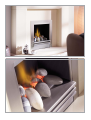
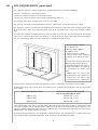
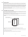
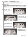
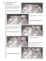
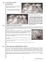
installation and user instructions
All instructions must be handed to user for safekeeping
Revision A - 06/09
Country(s) of destination - GB/IE
eko 2030
fuel effect gas fire
Eko 2030
INSTALLATION INSTRUCTIONS
Preliminary Notes Before Installation
This appliance is an Inset Live Fuel Effect appliance which provides radiant
warmth utilising the latest type burner technology.
The fire is designed to fit various types of fireplaces and natural draught flues
as listed in the Installation Requirements.
The appliance must be installed by a competent[1] person in accordance with
Gas Safety (Installation and Use) Regulations 1998.
Read all these instructions before commencing installation.
This appliance must be installed in accordance with the rules in force and only
used in a sufficiently ventilated space.
The appliance is designed for installation on to a non-combustible hearth of at
least 300mm depth.
This appliance is factory set for operation on the gas type, and at the pressure
stated on the appliance data plate.
Please note : Except where otherwise stated, all rights, including copyright in the
text, images and layout of this booklet is owned by Focal Point Fires plc. You are
not permitted to copy or adapt any of the content without the prior written permission of Focal Point Fires plc.
[1] GB - Gas SafeTM registered operatives (Northern Ireland only- CORGI registered operatives) are the only class of person considered as competent by the HSE under the Gas Safety (Installation and Use)
Regulations 1998.
© 2009 Focal Point Fires plc.
Page No. Section
Section
Contents
Contents
1
1.0 Important Notes
10.0 Gas Supply
2
2.0 Appliance Data
11.0 Fitting the Firebox
2
3.0 Installation Requirements
11.1 Cable Fixing
2
4.0 Site Requirements
11.2 Gas Connection
4
5.0 Ventilation
12.0 Fuel Bed Layout
4
6.0 Flue Boxes
13.0 Fireframe and Front
5
7.0 Unpacking the Appliance
14.0 Testing & Commissioning
5
7.1 Component Checklist
14.1 Operating the fire
5
8.0 Preparing the Appliance
15.0 Servicing
6
9.0 Preparing the Opening
16.0 Troubleshooting Guide
1.0
Page No.
6
7
7
8
8
8
8
8
10
12
IMPORTANT NOTES
This fire is an Inset Live Fuel Effect Gas Fire providing radiant warmth. It is designed to operate
on Natural Gas only. See Data Plate on appliance.
It is the LAW that all gas appliances and fittings are installed by a competent person (such as a
CORGI registered fitter) and in accordance with the Gas Safety (Installation and Use) Regulations
1998, the relevant British Standards for Installation, Codes of Practice and in accordance with the
Manufacturers’ Instructions. The installation shall also be carried out in accordance with the following regulations:
The Building Regulations issued by the Department of the Environment, the Building Standards
(Scotland) (Consolidation) Regulations issued by the Scottish Development Department.
BS 5871 part 2
BS 5440 part 1
BS 8303
BS 1251
Note - For Republic of Ireland, reference
should be made to the relevant standards
governing installation, particularly in regard
to flue sizing and ventilation. See IS813,
ICP3, IS327 and any other rules in force.
BS 6891
BS 6461 part 1
Failure to comply with these regulations could lead to prosecution and deem the warranty
invalid.
This appliance must be installed in accordance with the rules in force and used only in a sufficiently ventilated space. This appliance is intended for decorative purposes.
Consult all instructions before installation and use of this appliance.
This appliance is free from any asbestos material. Refractories and fuel bed are constructed from ceramic fibre.
1
© 2009 Focal Point Fires plc.
2.0
APPLIANCE DATA
Manual Control
Gas Group
G20 Natural Gas CAT I2H
Inlet Pressure
20mbar (+/-2.0mbar)
Max Energy Input (gross)
6.2kW
Min Energy Input (gross)
3.5kW
Pilot Energy Input (gross)
166W
Setting Pressure (cold)
17.5mbar (+/- 1.5mbar)
Main Injector Burner
Stereo size 77
Gas Inlet Connection
8mm compression
Gas Control Valve
Dungs BM 733/NGC6802
Ignition
Integral Piezo spark
Spark Gap
3.5 to 4.5mm
Weight
20KG
Please see Data Badge affixed to appliance for current data.
This appliance is for use only with the gas type, and at the pressure stated on the appliance Data
Badge, and is for decorative purposes.
3.0
INSTALLATION REQUIREMENTS
This appliance MUST NOT be installed into a room containing a bath or shower, or where steam may be
present. The fire has been designed to fit into a builders’ opening or fireplace conforming to BS 1251 (and
meeting certain dimensional requirements), or a suitable flue box complying with the constructional requirements of BS 715. The flue box must be installed onto a suitable non-combustible insulating surface at least
12mm thick, covering the entire base are of the box.
The flue must have an effective height of at least three meters, as measured from the hearth to the top of
the flue. Any flue damper plates or restrictors should be removed and no other restriction fitted to the flue.
Where removal is not practical, the restriction must be fixed in the fully open position.
A natural draught flue system is required, and if previously used for solid fuel or oil burning, the flue and
chimney must be swept prior to appliance installation. The flue must be checked before installation by using
a smoke pellet or similar to ensure proper draw and that leakage is not evident at any joints. Repair and retest as necessary before the appliance is installed.
The flue must be connected to only one fireplace, and the flue must not vent more than one appliance (i.e.
not shared with a gas back boiler). There must be no opening in the flue apart from the one that the appliance is installed into, and the one venting the gases into the air. A suitable terminal may be fitted, such as
class GC1, as regulations allow.
This appliance is suitable for use with a “lightweight” surround and back panel of 150ºc minimum rating.
4.0
SITE REQUIREMENTS
The fireplace opening should be inspected and repairs made where necessary. Any chair brick or fireback
may be left in place, providing that the dimensional requirements for debris collection and spigot clearance
are met.
The opening WIDTH and HEIGHT dimensions should be between 400mm and 460mm wide, and 540mm to
570mm high.
Opening DEPTH should be 210mm or greater. Opening DEPTHS include any plaster or infill panels which
form part of the installation. If the cable method of fixing the firebox is to be employed, an opening depth
of 240mm will be required.
2
© 2009 Focal Point Fires plc.
4.0
SITE REQUIREMENTS (continued)
This appliance requires a natural draught flue system which may be one of the following;
225mm x 225mm (9in x 9in) brick or stone.
175mm (7in) minimum diameter lined brick or stone.
175mm (7in) minimum diameter twin wall flue conforming to BS 715.
Any existing under grate draught device must be sealed off.
The opening wall must be non-combustible and have adequate flat surface for appliance sealing.
The appliance requires a hearth with non-combustible surface of at least 12mm thick. The top surface must
be at least 50mm above the surrounding floor level, or be surrounded by a raised edge or fender 50mm
high.
To enable the products of combustion to be cleared properly up the flue, the outlet on top of the firebox
must have a minimum 50mm clearance between it and the back wall of the opening or other obstruction.
The area immediately above the outlet must form a smooth path into the flue.
A. Opening height: 540mm
min/570 mm max.
B. Opening width: 400mm
min/460mm max.
C. Mounting depth: 210mm
D. Hearth must extend minimum
of 150mm either side of the opening.
E. Hearth must extend minimum of
300mm in front of the opening.
F. Non-combustible hearth must be
a minimum of 50mm in height, or
be surrounded by 50mm high
fender.
G. 500mm, this area must be flat
and vertical to ensure a good seal.
H. 585mm, this area must be flat
and vertical to ensure a good seal.
G
H
A
D
C
B
E
F
Any type of fire surround used with this appliance must be adequately sealed to the wall and floor.
A combustible shelf may be fixed to the wall above the fire, providing that it complies with the dimensions
given below.
Maximum depth of shelf
100mm (4in)
Minimum distance from finished
hearth to underside of shelf
745mm (29 1/4 in)
150mm (6in)
845mm (33 1/4 in)
203mm (8in)
895mm (35 1/4 in)
A non-combustible shelf may be fitted to within 10mm of the top edge of the fireframe. Combustible materials, such as wood, may be fitted to within 100mm (4in) of either side of the frame of the appliance, providing the forward projection does not exceed 100mm (4in). Any combustible side walls must be at least
500mm to the side of the radiant heat source.
As with all heating appliances, any decorations, soft furnishings, and wall coverings (i.e. flock, blown vinyl
and embossed paper) positioned too close to the appliance may discolour or scorch.
3
© 2009 Focal Point Fires plc.
5.0
VENTILATION
No purpose provided ventilation is normally required for this appliance. The requirements of other appliances operating in the same room or space must be taken into consideration when assessing ventilation.
If spillage is detected when commissioning the appliance then amongst other problems there may be insufficient natural ventilation for the correct operation of the flue. This is potentially a greater problem should
the property be of modern nature. If the appliance does not spill with windows open but does with windows
closed, this proves that lack of ventilation is the problem, if not, it will be the flue at fault. Installation of an
air brick is the best solution. Any ventilation fitted must comply with BS 5871 part 2 and BS 5440 part 2.
Spillage detected during commissioning is almost always a result of poor flue performance, which cannot be
corrected by any amount of ventilation.
For Republic of Ireland ventilation may be required, see IS 813, ICP3, IS 327, and any other rules in force.
6.0
PREFABRICATED FLUE BOXES
This appliance can be fitted into a number of proprietory flue boxes, provided that the minimum dimensions
given in the diagram below are complied with. The flue outlet of the fire must not obscure the flue outlet
from the flue box. A smooth path into the flue must exist.
Constructional Note: The frame of the fire, any back panel or other infill panel, and the flue box must be
sealed together so that there is no possibility of leakage between them. Adequate clearances to combustible
materials (e.g. false chimney breast construction) must be maintained.
The manufacturers’ instructions for the fitting of the prefabricated flue box shall be complied with at
all times.
175mm min internal
dia twin wall flue tube
540mm min
opening height
210mm Min depth
400 mm min
opening width
Some flue boxes may require minor adaption when fitting the fire using the cable fixing kit.
The firebox, base of the flue box, and the hearth may be drilled to allow plugs and screws to secure installation.
It is important that the sealing requirements of the appliance are met at all times and that the flue box is
well sealed to any back or infill panel.
Note: The DEPTH dimensions shown are inclusive of any back or infill panels.
4
© 2009 Focal Point Fires plc.
7.0
UNPACKING THE APPLIANCE
Stand the carton right way up, cut the strapping bands and remove the top end cap. Read all the instructions
before continuing to unpack or install this appliance.
Remove the box containing the fire front, and the bags and boxes containing the ceramic parts. Remove the
cardboard packing pieces, and any bags containing other fittings or parts. When all loose parts have been
removed, the outer sleeve may be lifted off to reveal the appliance. Check that the components supplied correlate with the checklist given in section 7.1. Please dispose of the packaging materials at your local recycling centre.
7.1
COMPONENT CHECKLIST
QUANTITY
1
Firebox and burner tray assembly.
1
Moulded ceramic fibre combustion matrix.
13
8.0
DESCRIPTION
Individually packaged ceramic pebbles.
3
Ceramic radiant panels.
1
Set of manufacturers instructions.
1
Cable fixing kit comprising; 2 cables, 2 tensioners, 2 clamps, 4 fixing eyes, 4 fibre rawl plugs.
3
Lengths of self adhesive sealing strip.
1
Rubber grommet.
PREPARING THE APPLIANCE
Removable shelf
Note: Ensure that the gas supply is isolated before
commencing installation of the appliance.
The fireplace opening and environment must be in
compliance with the specifications laid down in the
appropriate sections of these instructions.
Remove the appliance from its carton as described
previously and stand upon a dust sheet or similar.
Place the ceramics components and fixing kit safely
to one side.
Firstly, remove the stainless steel shelf from the firebox in order to access the burner. This is achieved by
removal of the two retaining screws, located under
the shelf at either side of the burner. After removal of the retaining
screws the shelf unit may be pulled forward and withdrawn from the
firebox. Next, remove the data plate by removal of the two data plate
retaining screws as shown. Now remove the burner from the assembly by releasing the two screws through the tray legs. The tray is now
free, and may be lifted away.
Shelf retaining screws located
each side of burner
The three radiant panels are factory fitted and should not need to be
removed. If, however it is necessary to remove or replace the panels,
then this procedure is described later, in the ‘Servicing’ section of this
instruction manual.
Apply the self adhesive sealing strips to the back of the fireframe to
give a continuous seal.
Knockout holes are provided in the rear and sides of the firebox for
use where concealed pipework is required. Where necessary, knock
out the appropriate hole with a sharp tap from a hammer, and fit the
rubber grommet supplied. A small incision can now be made in the
rubber to slip snugly around the outside of the pipe and sleeving. Do
not install or use the appliance without the seals in place. If a hole
is inadvertently opened, reseal with an intact grommet. Failure to fit
the seal correctly will cause flue suction to act upon the area under
the burner, resulting in poor performance and intermittent cutting out of the burner.
5
© 2009 Focal Point Fires plc.
9.0
PREPARING THE OPENING
Before installing the fire, check the flue using a smoke pellet. All of the smoke should travel up the flue and
exit correctly from the terminal. If problems are found, DO NOT fit the fire until corrective action is completed.
Protect the decorative hearth whilst pushing the firebox in and out of the opening. Part of the packaging will
make an ideal hearth saver pad.
Before running the gas supply into the opening, offer up the firebox to the fireplace to check the fit is good.
Ensure that it slides in correctly, the sealing face sits flat and square to the wall or infill panel, and that the
base is firm on the floor of the opening as no leaks are permissible here. At this stage it is essential to ensure
that the spigot outlet of the firebox is not restricted in any way. Remove the firebox and take any necessary
measurements before making good and preparing for final installation.
CABLE FIXING. For fixing of the fire by the cable method, see the relevant section. The cable fixing locations
should be marked on the back of the opening and the holes drilled. Fit the fibre rawlplugs and eyebolts to
these holes. Note: Plastic rawlplugs are NOT suitable for this application.
SCREW FIXING. For fixing by screw, mark and drill the firebox base, and the relevant points in the opening
or on the wall. Rawlplugs will again be required. Pre-punched holes are not provided for this purpose to allow
you to choose the optimum positions. Do not screw fix via the appliance frame as the screwheads will
be visible on the completed installation. The appliance frame is an integral part of the firebox.
GAS SUPPLY. Following preparation for the fixing method, the concealed gas supply, where required, can
now be put into place. Refer to the gas supply section for suggested pipe routes. The ends of the sleeving
in which the gas pipe is run should be sealed. The ends of the 8mm supply pipe should be temporarily sealed
to prevent the ingress of debris during fixing.
10.0
GAS SUPPLY ROUTING
When the opening is ready for installation of the fire, the gas supply can be routed as shown in the diagram
below.
This appliance has been designed for a concealed gas pipe supply routing,
however if an over the hearth type supply routing is unavoidable then this
may be achieved by drilling a 10mm diameter hole at the base of the appliance frame in the position detailed to the right. The supply can then enter
the appliance using the left or right hand knock out entry points.
IMPORTANT - A rubber grommet must always be used to seal
the firebox.
15mm
10mm
10mm dia.
Suggested Supply routes
Fireplace
Opening
Rubber
Grommet
Firebox
Gas valve inlet position
Over hearth routing (if necessary)
6
© 2009 Focal Point Fires plc.
10.0
GAS SUPPLY ROUTING (continued)
The gas pipe must be suitably protected where it passes through fireplace openings. An isolator cock or
restrictor elbow must be fitted to the incoming supply to facilitate servicing. Any sleeving should be sealed
to the pipe at its ends. The open end of the supply pipe should be sealed temporarily during the installation of the firebox to prevent the ingress of dirt and dust.
11.0
FITTING THE FIREBOX
The firebox may be fitted to the opening by using screw fixing or by the cable kit as described in the relevant
section. Leave the polythene coating in place until fitting procedures are complete to eliminate any
risk of scratching the decorative finish.
To fit the firebox, firstly check the fire goes fully back into the opening. Secure the fire box by drilling and
screwing down the frame or base of the firebox, or use the cable fixing method.
11.1
INSTALLATION BY CABLE FIXING KIT
If this method is to be adopted then an extra 30mm fitting
depth should be allowed for fitting depth for the firebox
becomes a recommended 240mm.
Drill the four holes for the rawl plugs, as shown in the diagram. If the fireplace configuration does not allow the exact
layout given, the eyebolts should be positioned as close to
the correct layout as possible.
A
B
A. 200mm
B. 350mm
C. 60mm
Dimension
can be +/10mm
C
Before finally fitting cables, ensure the self adhesive sealing
strips are in position on the back of the appliance frame. The
fireframe must be sealed evenly to the fireplace opening all
around the periphery.
Thread the tensioning cables through the holes in the top of the
firebox, then the eyelets, and finally through the lower holes in
the back of the firebox, as shown in the photographs.
Note: The burner tray MUST be removed as per relevant section to gain access to the cable adjusters.
Push the appliance back into to fireplace, centralise, and pull the
loose tensioning cables through the holes into the firebox.
Thread the tensioner bolts onto the cables, with the nuts screwed
down close to the tensioner head.
Slide the screwed nipple onto the cable, pull cable tight, and
tighten nipple.
The tension of the cable may now be adjusted by using a suitable
spanner on the tensioner nuts to pull the appliance tightly
against the fireplace opening. Visually inspect the seal and reseat
if necessary.
Note: DO NOT cut off excess cable. Surplus cable must not be
cut off, as it will be impossible to refit the fire after servicing. Coil
up the surplus cable, and locate at rear of firebox.
Note : If running a concealed gas supply, ensure grommets are secure around
incoming pipes.
7
© 2009 Focal Point Fires plc.
11.2
GAS CONNECTION
Refit the burner tray into the firebox, fit the two screws through the locating holes in the tray legs, and tighten.
Purge the gas supply thoroughly to remove air and dirt/debris BEFORE connection. Now disconnect the inlet
restrictor elbow from the inlet pipe. Connect the previously installed gas supply to inlet restrictor elbow, and
re-fit the restrictor elbow to the inlet pipe of the appliance.
If the data/control plate is not already fitted, attach with two screws, ensuring the control knob is free to
be depressed fully.
Refit the stainless steel shelf unit. Any protective film should be removed from the shelf at this stage.
Ensuring it rests upon the support bracket at the rear of the firebox insert the shelf back into the appliance.
Secure in place using two fixing screws - refitting is the reverse of removal as detailed in the previous section - 'Preparing the appliance'.
12.0
FUEL BED LAYOUT
Please refer to the relevant section of the user manual section of this booklet.
13.0
THE DECORATIVE FRAME AND FRONT
The decorative frame of the appliance is an integral part of the firebox, and cannot be removed. Any protective film should be removed at this stage.
The stainless steel shelf component is removable (see previous section - ‘Preparing the appliance’). The
appliance also features a hinged control cover which is retained in it’s closed position by a magnet. Any protective film should be removed from the control cover at this stage. The door is removable, should the need
arise, see the later ‘Servicing’ section of these instructions.
14.0
TESTING AND COMMISSIONING
Turn on and test the gas supply up to the fire for any leaks, in accordance with current edition of BS6891.
When the appliance is first used, protective oils coating the firebox may burn off. It is advisable to ventilate
the room during this period for at least one hour.
14.1
OPERATING THE FIRE
The pilot is visible through a viewing hole underneath the left hand side
of the shelf. Push in and turn the control knob to the SPARK position, and
hold there for a few seconds.
Continue turning anti-clockwise through the spark click to the PILOT
light position, ensuring the pilot has lit. If not, return the knob clockwise,
and repeat.
When the pilot lights after the spark, keep the knob depressed for
approximately ten seconds. Now release the knob and the pilot should
stay alight. If not, retry ignition. If the pilot is extinguished during use, wait three minutes before repeating
the ignition procedure.
To achieve the HIGH setting, push the control knob in slightly and continue turning anti-clockwise to the
high (large flame) position. The main burner should light after a few seconds.
To decrease the setting to LOW, turn the control knob clockwise to the low setting.
To turn to the PILOT position from the HIGH or LOW positions, press the control knob in, and return to the
pilot position and release.
To turn the fire OFF, keep the knob pressed in, return to the off position and release.
A safety interlock prevents re-ignition of the pilot flame until the thermocouple has cooled sufficiently to
allow the magnetic valve unit to reset itself.
8
© 2009 Focal Point Fires plc.
14.2
SPARK FAILURE
The gap between the spark electrode and the pilot should be 3.5 - 4.5mm to produce a good spark. There
should be no need to adjust this. If under any circumstances the electric spark fails, the pilot may be lit manually by proceeding with the ignition sequence as previously described, and after turning the control knob
through the spark position, the knob should be held in and the pilot lit with a taper.
14.3
SETTING PRESSURE
Remove the screw from the pressure test point.
The pressure test point is situated on the main injector pipe next to the pilot.
Attach a U gauge. Light the fire on the HIGH setting.
The setting pressure should be in accordance with the figures stated on page 2 of these instructions. The
fire is factory set to achieve these pressures, and any significant variation could indicate a supply problem.
If the pressure is too high, the gas supply meter may be set incorrectly. This should be checked with the fire
running and if necessary reset by the gas supplier.
If the pressure is too low, then check the meter governor pressure with the appliance running. If this is incorrect it will need to be reset by the gas supplier. If the setting pressure is too low, but the meter pressure is
acceptable, then a problem in the supply pipework is to be suspected. This will be dirt and debris, kinked
or inadequate size pipes, restriction in a fitting or solder flashing across a joint. (NOTE: you will not get an
accurate reading of the inlet pressure with a pressure gauge on the end of the supply pipe - this is the static pressure in the system. You must use a T piece and measure the supply pressure with the fire on High the dynamic pressure). Refit and tighten the screw into the pressure test point when the test is complete.
14.4
FLUE SPILLAGE MONITORING SYSTEM
This fire is fitted with a flue spillage safety device (ODS). If the fire shuts down during use for no apparent
reason then several things may be suspected. If a door or window has been opened creating a draught, then
pilot disturbance is the problem, and removal of the draught should resolve this. If a grommet seal has been
left out of the firebox then this also will also cause intermittent shutdown. The gas pressure reaching the
fire must also be checked. The thermocouple connection into the back of the gas control valve may also have
worked loose during installation, simply tighten to remedy if this is the case.
If pilot disturbance is not the cause, then the ODS safety system may be in operation. Switch the appliance
OFF, check the flue and carry out any remedial work required. Relight the fire and carry out a spillage test.
DO NOT allow the appliance to be used if it continues to fail a spillage test.
The aeration hole of the pilot must be carefully cleaned out on each annual service to ensure continued function of the ODS.
The spillage monitoring system shall not be adjusted, modified, or put out of operation by the installer. Any
spare parts fitted MUST be of a type supplied for the purpose by the appliance manufacturer.
If the fire is not spilling, then further guidance should be sought, using the Troubleshooting section as a
guide.
14.5
TESTING FOR SPILLAGE
Close all doors and windows to the room containing the appliance. Let the fire run on HIGH for five minutes.
Take a smoke match, light it, and using a smoke match tube, hold it at the top edge of the fire opening,
25mm down and 25mm in. Starting 50mm in from either side, run the smoke match across the opening. All
the smoke should be drawn away up the flue. Any smoke returning into the room indicates that spillage is
occurring. If the initial spillage test fails, run the fire for a further 10 minutes and repeat the test. When the
test has been completed satisfactorily, repeat with any extractor fans in the premises running on the highest setting, and any communicating doors open. Finally, repeat with all doors open.
NOTE: If spillage is still indicated after undertaking all of the above, there may be a fault in the flue,
or insufficient ventilation is present.
If the problem cannot be rectified immediately, then expert advice should be sought. Inform the user, disconnect the fire, and attach an explanatory label.
9
© 2009 Focal Point Fires plc.
14.5
TESTING FOR SPILLAGE (continued)
Cross section of smoke match tube
Tube
Crimp
Match
Make a smoke match tube from 10mm
diameter tube. Seal off one end and
crimp the tube to prevent the smoke
match from sliding down inside.
14.6
A . 2 5 m m
down
from
top of opening
B. 25mm in
from front of
opening.
C. Disregard
outer 50mm
either side of
fireplace
opening
Fireplace Opening
A
C
B
C
Smoke Match
In Tube
BRIEFING THE CUSTOMER
All instructions must be handed to the user for safekeeping. Show the customer how to light and control
the fire.
After commissioning the appliance, the customer should be instructed on the safe use of the appliance and
the need for regular servicing. Frequency of service depends on usage, but MUST be carried out at least one
annually.
Scratched and other superficial damage to the matt black paintwork of the appliance can be covered with
matching heatproof spray. Use only the manufacturers’ recommended spray paint. Paint only when the fire
is OFF and cold. Always mask off the surrounding area to prevent contamination with overspray. Ventilate
the room during the use of the spray.
DO NOT attempt to spray paint the pebbles or ceramics, or wash them in water.
15.0
SERVICING
Ensure that the fire is fully cold before attempting service. A suggested procedure for servicing is detailed
below.
1. Lay out the dust sheet and tools.
2. Carefully remove the ceramic components.
3. Check frame top for discolouration and signs of spillage.
4. Isolate the gas supply and disconnect the gas supply pipe. Remove the appliance shelf, control
knob and spindle, and the two screws securing the tray to the firebox.
5. Lift the burner tray from the firebox.
6. Remove the firebox as detailed in the relevant section.
7. Check the area behind the firebox for rubble accumulation and remove. If debris is excessive,
initiate remedial work on the flue.
8. Check the flue with smoke pellet for correct operation.
9. Re-fit the firebox using new seals where necessary.
10. Strip off the burner pipes and clean thoroughly.
11. Clean out the injector and pilot assembly. DO NOT attempt to dismantle the pilot unit.
12. Ensure the injector is aligned squarely with the venturi tube.
Re-assemble and re-fit the burner tray.
13. Re fit the control knob, spindle and appliance shelf and replace the ceramics, using genuine
spares where necessary.
14. Turn on the gas supply, and leak test.
15. Check any purpose provided ventilation is un-obstructed.
16. Light the fire and test for spillage.
17. Check setting pressure and safe operation of the appliance.
For specific servicing instructions, see the relevant sections.
10
© 2009 Focal Point Fires plc.
15.1
CLEANING THE CERAMIC FUEL BED
Remove the ceramic components. Gently clean in the open air. Be careful not to create dust from the pebbles. Where necessary replace damaged components with genuine spares. Seal scrap components in plastic
bags and dispose of at proper refuse sites as directed.
Re-fit the pebbles carefully by referring to the relevant section of these instructions.
15.2
REMOVING THE FIREBOX
Remove the ceramics and stainless steel shelf unit. Then remove the firetray as previously described. Uncoil
the fixing kit cables from the rear of the firebox, remove the screwed nipples and tensioning adjusters. The
firebox can now be withdrawn from the opening and outwards onto the protected hearth. Inspect the fireplace opening for debris, and if excessive rectify the flue before proceeding further. Check the seal around
the fireframe and replace if necessary. Refitting of the firebox is described in the relevant section.
15.3
REMOVING THE CERAMIC PANELS
Remove the side panels first by holding each panel at the top and bottom and gently releasing the panel
inwards. When the rear of the side panels are free, the front of the side panels may be released from the
channels at the front of the sidebox. With the side panels removed the rear panel is free to be released.
Handle the panels with extreme care! The ribbed pattern is fragile. Refitting is the reverse of removal.
15.4
DISMANTLING THE BURNER TRAY
Remove the tray as previously described. The pilot unit can be removed by undoing the tubing nut, the thermocouple nut on the rear of the valve, lint arrestor, two securing screws, and lifting away. Remove the tubing nut from the valve end of the pilot pipe, and blow through to dislodge any debris that may be present.
Clean the exterior of the pilot assembly with a soft brush and blow through the flame ports on the pilot head.
Check the aeration holes are free from lint or dirt. The pilot assembly is a non-serviceable item, and should
not be taken apart. The aeration hole must be absolutely clear internally for proper operation. A thoroughly cleaned (inside and out) oxypilot will cure a wide range of ignition faults.
Remove the two tubing nuts on the ends of the gas pipe to the injector elbow. Release the screw through
the supporting leg and lift assembly clear. The injector pipe can now be checked for debris. Remove the nut
retaining the injector elbow. Blow through the elbow to remove any debris.
The valve is not field serviceable, apart from the pilot filter. Remove the control knob by pulling it forwards,
then remove the largest of the three screws on the face of the valve. Slide the filter out and clean away any
debris that may have accumulated. The filter element should also be blown clean. This component should
not require replacement, however if signs of deterioration are evident then a genuine spare must be used.
If a large amount of debris is present in the filter then the pipework and control should be thoroughly
cleaned before re-assembly.
11
© 2009 Focal Point Fires plc.
16.0
TROUBLESHOOTING GUIDE
Fire sparks but pilot does not light
No gas to fire, check isolators are open.
Pipework blockage, clean out.
Air not fully purged, repurge supply or wait longer.
Spark earthing to metal work, reset gap correctly.
Blocked pilot, clean out internally.
Pilot lights but then goes out
Severe restriction in gas supply, clear obstruction.
Faulty thermocouple, replace pilot unit.
Hold control knob in for longer.
Manual versions only Check control knob does not foul data plate.
Fire does not spark at pilot
HT lead detached, refit.
Spark gap too large or small, reset correctly.
Faulty piezo unit, replace.
Debris shorting out electrode, clean.
Fire runs for a time and then cuts off
Excessive room draught or flue pull, rectify.
Loose or faulty thermocouple, rectify.
ODS system in operation.
Firebox grommet seal not fitted, rectify.
Lint in pilot aeration hole, clean thoroughly internally
Pilot flame shrinks when fire is on high Poor gas flow to fire, check pressure with fire on high.
If pressure is low, remove any restriction in pipework or valve.
Check all isolators are adequately sized and fully open.
Check meter pressure is adequate.
Air leak under base of firebox, rectify.
Lint in pilot aeration hole, clean thoroughly internally.
Fire smells when first lit or in use
Newness smell from brand new appliance.
Spillage occurring. Carry out spillage test and rectify
any problems.
Low temperature sealants or combustible materials used in
incorrect positions.
Air leak under base of firebox, rectify.
12
© 2009 Focal Point Fires plc.
USER INSTRUCTIONS
Section
1.0
2.0
3.0
4.0
5.0
6.0
7.0
8.0
1.0
Contents
Important Notes
Clearances to Combustibles
Ventilation
Fuel bed layout
Operating Instructions
Flue Spillage Monitoring System
Cleaning
List of Spares
Page No.
1
1
2
2
4
4
5
5
IMPORTANT NOTES
The installation of this fire MUST only be carried out by a competent person (such as a CORGI registered fitter) in accordance with the Gas Safety (Installation and Use) Regulations 1998, the relevant British Standards,
Codes of Practice, the Building Regulations and the manufacturers’ instructions.
Failure to comply with the above recommendations could lead to prosecution and invalidate the appliance
warranty.
Please ensure you are handed all of the manufacturers documents on completion of the installation. This will
include these instructions.
Always keep a note of the installer’s name and address, the original purchase receipt and the date of installation for future reference.
The fire and flue should be serviced regularly to ensure continued safe operation. See the servicing section
for further details. Frequency of service will depend on use, but MUST be carried out at least once annually.
Parts of this appliance become naturally hot during use. It is recommended that a suitable fire guard conforming to BS 8423 is used, especially where young children, the elderly, or infirm are concerned.
Combustible items, such as flooring and furniture, and soft wall coverings (such as blown vinyl or embossed
paper) may discolour if fitted too close to the fire. See relevant section for further details on clearances to
combustibles. No combustible material or flooring should protrude onto the hearth.
DO NOT burn any foreign material on this fire, the fuel effect must be of the correct type and laid out in
accordance with the relevant section of these instructions. Failure to do so could create a hazard or lead to
sooting.
Before the appliance is installed, the chimney should be swept. All flues should be checked by the installer
to ensure there are no defects or obstructions that may prevent the flow of combustion products.
This appliance is fitted with a flue blockage safety device which will shut down the fire if abnormal flue conditions occur. It is NOT a substitute for an independently mounted Carbon Monoxide detector.
The fire is only suitable for use with the gas type for which it is supplied. This appliance is intended for decorative purposes.
2.0
CLEARANCES TO COMBUSTIBLES
A combustible shelf may be fixed to the wall above the fire, providing that it complies with the dimensions
given below.
Maximum depth of shelf
Minimum distance from finished
hearth to underside of shelf
745mm (29 1/4 in)
100mm (4in)
150mm (6in)
845mm (33 1/4 in)
203mm (8in)
895mm (35 1/4 in)
A non-combustible shelf may be fitted to within 10mm of the top edge of the fireframe.
Combustible materials, such as wood, may be fitted to within 100mm (4in) of either side of the frame of the
appliance, providing the forward projection does not exceed 100mm (4in).
1
© 2009 Focal Point Fires plc.
2.0
CLEARANCES TO COMBUSTIBLES (continued)
Any combustible side walls must be at least 500mm to the side of the radiant heat source.
As with all heating appliances, any decorations, soft furnishings, and wall coverings (i.e. flock, blown vinyl
and embossed paper) positioned too close to the appliance may discolour or scorch.
3.0
VENTILATION
No purpose provided ventilation is normally required for this appliance. The requirements of other
appliances operating in the same space or room, and the results of a spillage test must be taken into consideration when assessing ventilation requirements, this will have been carried out by your CORGI registered
installer.
For Republic of Ireland, ventilation may be required, see IS 813, ICP3, IS 327, and any other rules in force.
4.0
FUEL BED LAYOUT
The appliance is supplied with 13 individually wrapped hand-finished ceramic
pebbles and 1 combustion matrix.
1. Remove the combustion matrix from
its protective packaging, and position
onto the burner as shown. The letters ‘A
B C D’ should be facing forward.
2. Remove the pebbles from the protective packaging. On the bottom of the
pebbles are the letters A to M. You will
need to select the pebbles in alphabetic
order beginning with ‘A’.
A
Place the pebble ‘A’ onto the peg ‘A’ on
the matrix as shown.
3. Place the pebble ‘B’ onto the peg ‘B’ on
the matrix as shown. The pebble can only
fit onto the peg one way - do not force it
on.
B
4. Place the pebble ‘C’ onto the peg ‘C’
on the matrix as shown. When pebble ‘B’
is in position this pebble can only fit onto
the peg one way - do not force it on.
C
2
© 2009 Focal Point Fires plc.
4.0
FUEL BED LAYOUT
(continued)
5. Place the pebble ‘D’ onto the peg ‘D’
on the matrix as shown. When pebble ‘C’
is in position this pebble can only fit onto
the peg one way - do not force it on.
D
E
6. Place the pebble ‘E’ onto the peg ‘E’ on
the matrix as shown.
7. Place the pebble ‘F’ onto the peg ‘F’ on
the matrix as shown. The pebble should
be orientated so it sits slightly over the
hole in the combustion matrix.
F
8. Place the pebble ‘G’ onto the peg ‘G’
on the matrix as shown.
G
9. Place the pebble ‘H’ onto the peg ‘H’
on the matrix as shown.
H
3
© 2009 Focal Point Fires plc.
4.0
FUEL BED LAYOUT
(continued)
I
10. Place the pebbles ‘I’ and ‘J’ onto the
four large pebbles on the left hand side
of the fuel bed as shown.
K
5.0
L M
J
11. Place the pebbles ‘K’, ‘L’ and ‘M’
onto the four large pebbles on the left
hand side of the fuel bed as shown.
The fire is designed to operate correctly with the pebbles supplied when
assembled according to the instructions. Never add to the thirteen pebbles, or change them for a different
type. Never throw rubbish or other
matter onto the fuel bed. Due to the
light colour of the pebbles, some discolouration/sooting is to be expected
during normal use.
OPERATING INSTRUCTIONS
The pilot is visible through a viewing hole underneath the left hand side of the stainless steel shelf. Push in
and turn the control knob to the SPARK position, and hold there for a few seconds. Continue turning anticlockwise through the spark click to the PILOT light position, ensuring the pilot has lit. If not, return the knob
clockwise, and repeat.
When the pilot lights after the spark, keep the knob depressed for
approximately ten seconds. Now release the knob and the pilot should
stay alight. If not, repeat ignition. If the pilot is extinguished during use,
wait three minutes before repeating the ignition procedure.
To achieve the HIGH setting, push the control knob in slightly and continue turning anti-clockwise to the high position. The main burner should
light after a few seconds.
To decrease the setting to LOW, turn the control knob clockwise to the
low setting.
To turn to the PILOT position from the HIGH or LOW positions, press the control knob in, and return to the
pilot position and release.
To turn the fire OFF, keep the knob pressed in, return to the off position and release.
6.0
FLUE SPILLAGE MONITORING SYSTEM
This fire is fitted with a flue spillage safety device (ODS). If the fire shuts down during use for no apparent
reason then several reasons may be suspected. If a door or window has been opened creating a draught,
then pilot
disturbance could be the problem, and removal of the draught should resolve this. The fire
can then be re-lit in accordance with the previous section. A sealing grommet may have been ommited when
the fire was installed, and the original installer should be called to check this, the gas pressure and pipework.
If pilot disturbance is not the cause, then the ODS safety system may be in operation. Switch the appliance
OFF, call in your installer to check the flue and ventilation and carry out any remedial work required. DO NOT
allow the appliance to be used until the flue system is passed as safe.
4
© 2009 Focal Point Fires plc.
7.0
CLEANING
Before carrying out any of the following operations, ensure that the fire is OFF and completely cold.
Debris that may form on the firebed should be periodically removed by a competent person. Large deposits
could indicate deterioration of the flue. This should be repaired by a competent person, and the fire serviced before further use.
STAINLESS STEEL AREAS - These parts may be cleaned using an appropriate metal polish. Clean only in the
direction of the grain. Alternatively, a small amount of baby oil applied in the direction of the grain, with a
soft, lint free cloth.
Another effective way to restore the ‘as new’ look to the stainless steel parts, is use of a proprietary car interior cleaning agent such as ‘Cockpit shine’. This should be sprayed directly on to the metal and then wiped
off with a clean lint free cloth.
It is strongly recommended to test clean on a small inconspicuous area firstly to ensure the cleaning substance(s) are suitable.
Before cleaning, always ensure that the fire is OFF and completely cold.
PAINTED AREAS - These can be cleaned using a dry cloth.
PEBBLES AND CERAMICS -Remove the ceramic components. Gently clean with a soft brush in the open air. Do
not create dust from the pebbles. Where necessary replace damaged components with genuine spares. Seal
scrap components in plastic bags and dispose of at proper refuse sites as directed.
Do not attempt to wash or otherwise clean any ceramic part using water as this will destroy them.
Re-fit the pebbles carefully by referring to the relevant section of these instructions.
LIST OF SPARES
PART NO.
ITEM
F550134
Pack of 13 hand decorated pebbles, and combustion matrix.
F550133
Pack of 3 ceramic tiles.
F730006
Pilot unit
F710638
Stainless steel shelf assembly
F710640
Stainless steel door assembly
[1] GB - Gas SafeTM registered operatives (Northern Ireland only- CORGI registered operatives) are the only class of person considered as competent by the HSE under the
Gas Safety (Installation and Use) Regulations 1998.
As our policy is one of continuous improvement and development , we hope therefore you will understand we must retain the right to amend details and/or specifications without prior notice.
5
© 2009 Focal Point Fires plc.
F860629
8.0


![eko 4000 series installation manual A [EN]:XL03](http://vs1.manualzilla.com/store/data/006898434_1-46c26fba35bf59407139a85b77984d70-150x150.png)