1
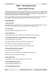
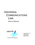
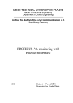
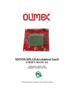
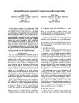
Design Note DN401
Interfacing CC1020/1 to the MSP430
By Giuseppe Mazzoleni
Keywords
•
•
•
•
1
•
•
•
•
MSP430
CC1020
CC1021
CC1070
Application Example
MSP430 and SmartRF04®EB
Interfacing CC1020 using SPI
Protocol Example
Introduction
The purpose of this design note is to show
how to interface the CC1020 EMX to the
MSP430F1xx/41x family. The example
shows the interconnection between the
CC1020/1
transceiver
and
the
MSP430F169. The protocol defined in
application note AN025 [1][2] has been
ported to the MSP430 where the main
functionalities are maintained (transceiver
configuration through the SPI interface
and RF communication).
The software handles the transceiver and
MCU configuration and a basic RF
communication protocol. The hardware
consists of an MSP-FET430 Development
Tool from Texas Instruments equipped
SWRA115
with an MSP430F169 MCU. The kit can
be connected to the CC1020 hosted on
the SmartRF®04 EB from Chipcon/Texas
Instruments. An auxiliary node must be
used to implement and test the RF
protocol.
The software is compatible with the IAR
C/C++ compiler and the MSP-GCC
compiler from GNU. Any SPI capable
interface module within the MSP430 family
is supported within the code. Bit banging
functions can also be easily added. This
approach is obviously more flexible but on
the other hand it can be slow with a slow
microcontroller.
Page 1 of 12
Design Note DN401
Table of Contents
KEYWORDS.............................................................................................................................. 1
1
INTRODUCTION............................................................................................................. 1
2
ABBREVIATIONS........................................................................................................... 2
3
DESCRIPTION................................................................................................................ 3
4
HARDWARE ................................................................................................................... 3
5
CC1020/1 ........................................................................................................................ 7
6
SOFTWARE.................................................................................................................... 7
6.1
PACKET PROTOCOL .................................................................................................... 8
6.2
SOURCE FILES ........................................................................................................... 8
7
MODIFICATION .............................................................................................................. 9
8
REFERENCES.............................................................................................................. 10
9
GENERAL INFORMATION .......................................................................................... 11
9.1
DOCUMENT HISTORY................................................................................................ 11
10
IMPORTANT NOTICE .................................................................................................. 12
2
Abbreviations
ADC
DCLK
DIO
DK
DMA
EB
EM
FLASH
GPIO
MCU
PCLK
PDI
PDO
PSEL
RAM
SOF
SPI
SVS
UART
USB
USI
Analog to Digital Converter
Data Clock
Data Input/Output
Development Kit
Direct Memory Access
SmartRF®04EB evaluation board
Evaluation Module
Non-volatile memory for storing of, mainly, program code
General Purpose Input/Output pin
Micro Controller Unit
Programming Clock – SPI interface
Programming Data Input
Programming Data Output
Programming Chip Select
Random Access Memory
Start Of Frame
Serial Peripheral Interface
Supply Voltage Supervisor
Universal Asynchronous Receiver/Transmitter
Universal Serial Bus
Universal Serial Interface
SWRA115
Page 2 of 12
Design Note DN401
3
Description
The example introduced here exploits two MSP430F169 microcontrollers connected to two
CC1020/1 transceivers. The microcontrollers and the transceivers are interfaced through a
MSP-FET430 socket module [5], a SmartRF04®EB, and the CC1020/1 EMXs. Two nodes are
required to establish a half duplex RF link. The two evaluation boards are belonging to the
CC1100/CC2500 DK [6] while the two evaluation modules are included in the associated
CC1020DK [7]. The evaluation boards can be easily substituted by a specific hardware
defining the correct interface between the microcontroller and the transceiver [3][4]. We
followed this type of approach to focus our attention on the software handling. A complete
example project is provided with the code. The purpose of this project is to demonstrate the
use of the library together with the Chipcon/Texas Instruments DK. It is intended to provide a
boost in the development of MSP430/CCxxxx-based products but is not a comprehensive
guide to using the CC1020/1. An overview of the connection schema is depicted in Figure 1.
Figure 1. Bidirectional RF link, MSP430, SmartRf04®EB, and CC1020
4
Hardware
The MCU chosen for the design is the MSP430F169 [8]. This MCU has several peripherals; it
integrates a 12-bit analog to digital converter (ADC12) with built-in voltage reference and
temperature sensor, a dual 12-bit D/A converter, and two universal serial
synchronous/asynchronous communication interfaces. This enables easy interface to various
sensors directly. In addition to the peripherals this device features 60Kbytes of Flash program
memory, 2Kbytes of RAM and DMA to support quite complex wireless networking protocols.
There is a wide choice of drop in replacement MSP430 derivatives that can be used on this
hardware platform based on the end applications and memory requirements. Some
compatible devices are listed in Table 1. It must be pointed out that this controller has
processing and memory capacity which exceeds the requirement of the software example, so
this software could execute on smaller microcontrollers.
SWRA115
Page 3 of 12
Design Note DN401
Part Number
Flash
RAM
GPIO
ADC
Other Peripherals
MSP430F156
24 KB
1 KB
48
12-bit SAR
2 DAC 12, Analog Comparator, DMA, SVS
MSP430F168
48 KB
2 KB
48
12-bit SAR
2 DAC 12, Analog Comparator, DMA, Hardware
Multiplier, SVS
MSP430F149
60 KB
2 KB
48
12-bit SAR
Analog Comparator, Hardware Multiplier
MSP430F148
48 KB
2 KB
48
12-bit SAR
Analog Comparator, Hardware Multiplier
MSP430F167
32 KB
1 KB
48
12-bit SAR
2 DAC 12, Analog Comparator, DMA, Hardware
Multiplier, SVS
MSP430F1611
48 KB
10 KB
48
12-bit SAR
2 DAC 12, Analog Comparator, DMA, Hardware
Multiplier, SVS
MSP430F147
32 KB
1 KB
48
12-bit SAR
Analog Comparator, Hardware Multiplier
MSP430F2011
2 KB
128 B
10
Slope
Analog Comparator, Timer UART
MSP430F2013
2 KB
128 B
10
Slope
Analog Comparator, Timer UART USI for SPI
Table 1. Some MSP Microcontrollers Suitable for this Type of Application
The microcontroller can be programmed using a JTAG module, MSP430FET, available from
TI [5]. In this example the SmartRF®04 is used as a motherboard for the CC1020EMX,
interfacing the MSP430F169 and the CC1020/1 radio transceiver. The motherboard (EB) is
populated with 0-ohm resistors which connect the signal lines from the EM to the USB MCU
and the various peripherals on the EB board. The 0-ohm resistors must be removed to isolate
the USB MCU from the EM selectively for all the signals. The signal lines can then be
controlled by for instance another MCU development board (MSP-FET430) by connecting it
to the I/O connectors (P11 I/O_B and P10 I/O_A). The I/O connectors bring out all the signals
from the EM connectors. These connectors make it easy to attach additional external circuitry
using a ribbon cable to connect a prototyping board (see Figure 2 and Figure 3). The
following describes which signals are routed to the external headers (P10 and P11). In order
to activate the connection between the prototyping board and the transceiver EM only a set of
six signals is required (refer to Table 2; highlighted light blue rows). In addition the prototyping
board can also exploit the supply voltage provided by the SmartRF®04 motherboard (3.3V,
highlighted light yellow rows). The SmartRF®04 can be powered in several different ways;
DC, USB, or Battery powered. Please refer to the DK user guide [6] to obtain more details
about the power supply configuration.
Figure 2. System Overview; Connection of the MCU with the EM through the EB
SWRA115
Page 4 of 12
Design Note DN401
Figure 3. Basic Connection MSP430 and SmartRF®04EB
P10 I/O Connector A
P11 I/O Connector B
PIN
PIN
Function
1
1
2
2
Function
3
Mic input
3
+3.3V
4
+3.3V
4
LED4
5
+3.3V
5
LED1
6
CC102X - DIO
7
Audio output
8
CC102X - DCLK
9
LED2
10
SDA (LCD display)
11
LED3
6
7
Push button
8
9
RS-232 RD
10
11
RS-232 TD
12
13
RS-232 RTS
14
15
SCL (LCD display)
13
CC102X - PSEL
14
Joystick push, RS-232 CTS
16
17
12
15
CC102X - PCLK
16
Joystick
18
17
CC102X - PDI
18
GND
19
Potmeter
19
CC102X - PDO
20
GND
20
GND
Table 2. I/O Connector A and B Pin Out
Table 3 summarizes which 0-ohm resistors must be removed in order to isolate the selected
signal from the USB MCU which governs the SmartRF®04 motherboard. The signals which
directly interface the external prototyping board with the EMX are highlighted.
SWRA115
Page 5 of 12
Design Note DN401
Signal Name
Resistor
Function
SO/GDO1/MISO
R117
SPI MISO SO/PDO
SCLK
R115
SPI Serial clock/PCLK
LED3
R113
LED3 (yellow), active low
LED_4
R120
LED4 (Blue), active low
JOY
R106
Joystick input (analogue coded voltage)
LED2
R111
LED2 (Red), active low
LED1
R110
LED1, (Green), active low
POT
R107
Potmeter input
JOY_PUSH
R112
Joystick pushed
PWM_OUTPUT
R105
PWM audio output
BUTTON_PUSH
R101
Button pushed
MIC_INPUT
R104
Audio input
SCL
R124
I2S clock (for LCD)
SDA
R123
I2S data (for LCD)
GDO2/DC
R122
Transceiver/Transmitter DCLK
GDO0/DD
R121
Transceiver/Transmitter DIO
UART_RD
R102
UART RD
UART_TD
R103
UART TD
CS/SS
R114
SPI slave select signal / PSEL
MOSI
R116
SPI MOSI SI/PDI
Table 3. Connection of Peripherals on SmartRF® 04EB
The MSP430 communicates to the CC102x via the SPI bus on USART1. Table 4 shows the
port pin connections and the signal names.
SWRA115
Page 6 of 12
Design Note DN401
MSP430 pin name
Signal Name
P1.0/TACLK
LED1
P1.1/TA0
LED2
P1.2/TA1
LED3
P1.3/TA2
LED4
P1.4/SCLK
Push button
P4.0/TB0
Joystick Push/CTS
P6.0/A0
Joystick
SmartRF04® Peripherals
LEDs (optional)
S1 Button (optional)
Joystick (optional)
P2.4/CA1/TA2
CC102X GDO0 / DIO
P2.6/ADC12CLK/DMAE0 SFD
CC102X GDO2 / DCLK
P5.3/UCLK1
CC102X SCLK / PCLK
P5.2/SOMI1
CC102X SO/GDO1 / PDO
P5.1/SIMO1
CC102X SI / PDI
P5.0/STE1
CC102X CSn / PSEL
P3.1/SIMO0/SDA
SDA (LCD display)
P3.3/UCLK0/SCL
SCL (LCD display)
P3.4/UTXD0
RS-232 TD
P3.5/URXD0
RS-232 RD
CC102x EMX
SMBus LCD (optional)
RS232 level shifter
(optional)
Table 4. MSP430 Pin and Corresponding Signal Name on the SmartRF04®EB
5
CC1020/1
The MSP430 configures and controls the CC102x via a high speed SPI bus. Other signals to
and from the CC102x are required to successfully acquire packets from the RF transmission.
Please refer to CC102x documentation for more information about the signal definitions and
their usage [9].
6
Software
The software developed for the MSP430F169 microcontroller is written for the IAR MSP430
C-compiler. Configuration of the CC102x is performed using general I/O pins and the
MSP430’s SPI interface. The demo application is simple: you can send ASCII characters from
one PC to the other. Furthermore, pressing a switch on one board causes a corresponding
LED on another board to toggle. The highest priority task of the software is performed by the
external interrupt handler, which is triggered by transitions in the DCLK clock coming from the
CC1020.
The main program handles state transitions, writes data from the RX buffer to the UART,
reads any incoming data from the UART, stores it in the TX buffer, and handles the time-out
and button de-bouncing.
Configuration of the CC1020 is performed using the MSP’s SPI interface. For more details on
CC1020 configuration issues, see AN023 [3].
Most of the microcontroller’s SRAM data memory is used for buffering the incoming and
outgoing data streams. When data arrives from the UART, the UART main program stores
the data in the TX buffer, and an RF packet is sent only after a timeout or when the buffer is
SWRA115
Page 7 of 12
Design Note DN401
full. When data is received via RF, the data is buffered in the RX ring buffer, and sent to the
PC via the UART.
6.1
Packet protocol
The protocol chosen for the RF modem is a simple variable-length packet protocol where the
maximum packet length is 64 bytes. If the modem receives a packet with a greater data
length than this, the packet is discarded (see Table 5).
Field
Length
Format
Preamble
4 bytes
Alternating 0s and 1s
SOF
2 bytes
0x33CC for modem application
Unit address
1 byte
0 for broadcast, 1-255 for unit address, not currently used
Data length
1 byte
Length of data payload
Data Variable
Variable
Data payload, maximum length of the packet is 64 bytes
Table 5. Data Protocol
6.2
Source Files
The software consists of several source code files. A quick overview of the files is provided in
Table 6.
File name
Short description
main.c
Main program source file
modemhw.h
Header file defining the I/O pin / SPI usage and RF packet format
cc1020.c
Function library for configuring and using CC1020. See application note [3]
cc1020.h
Header file for cc1020.c, also includes definitions for all the registers of the CC1020
usart.c
RS232 USART0 initialization, character transmission
interrupt.c
Contains the RF modem interrupt handler
main.h
Header file used by interrupt.c to gain access to variables shared with the main program
config.c
Configuration of the CC1020, calls to the cc1020.c
Table 6. Summary of Software Source Files
Figure 3 shows a stack diagram of the library. Note that one of the files displayed in the stack
is the standard definition file for the specific MSP430 device being used. This file is included
with the development environment being used to create the MSP430 software.
main.c
Application
SPI - Calibration
functions
usart.c
config.c
interrupt.c
CC1020.c
main.h
modemhw.h
CC1020.h
TX / RX
RF packets
msp430x16x.h
Hardware
configuration
Figure 3. Code Stack
SWRA115
Page 8 of 12
Design Note DN401
The software is implemented as a state machine with three different states (refer to Figure 4).
In the IDLE state, the modem looks for a valid incoming preamble and for data from the RS232 interface. If the RF modem detects a valid incoming preamble and it is followed by a valid
start-of-frame (SOF) word, the modem enters the RX state. If the transmit buffer is full or if the
timeout period has expired since the last character was received from the RS-232 interface,
the modem enters the TX state. In the RX state, header data is handled in the interrupt
handler; data is buffered in a circular buffer and transmitted via the RS-232 interface in the
main program. In the TX state, the data in the transmit buffer is sent to the CC1020 for
transmission. State switching is performed by the main program; the interrupt routine updates
a NextState variable when a state change occurs.
Valid preamble
and SOF
TX buffer full or
time out elapsed
idle
RX
Finished receiving
data or error
detect
TX
Finished
sending data
Figure 4. State Diagram
7
Modification
The hardware configuration can be modified adding an external crystal in order to increase
the speed of the MCU and have higher frequency accuracy. Other peripherals, which are
available on the SmartRF04®EB, can be interfaced with the microcontroller developing more
complicated applications.
The RF connection could be upgraded designing a simple star network configuration and also
the power consumptions of the system can be drastically optimized.
The protocol should take into account the possibility of a handshaking mechanism among the
RF nodes defining for example Binding and Acknowledge packets. The execution time of the
interrupt routine, which handles the reception and the transmission of the RF packets, can be
improved exploiting a hardware serial interface or rewriting the code at a lower level.
SWRA115
Page 9 of 12
Design Note DN401
8
References
[1]
AN025 - CC1020 RF MODEM, Technical document (swra067.pdf)
[2]
AN025 - CC1020 RF MODEM, Associated code files (swra067.zip)
[3]
AN023 - CC1020 MCU Interfacing, Technical document (swra069.pdf)
[4]
AN023 - CC1020 MCU Interfacing, Associated code files (swra069.zip)
[5]
MSP-FET430 FLASH Emulation Tool, User's Guide (slau138c.pdf)
[6]
CC1150/1100/2500/2550DK, User Manual (swru040a.pdf)
[7]
CC1020/1070 DK, User Manual (swru052.pdf)
[8]
Mixed Signal Microcontroller, Data sheet (msp430f169.pdf)
[9]
CC1020 Single Chip Low Power RF Transceiver for Narrowband Systems, Data
sheet (cc1020.pdf)
SWRA115
Page 10 of 12
Design Note DN401
9
9.1
General Information
Document History
Revision
SWRA115
Date
2006.10.06
Description/Changes
Initial release.
SWRA115
Page 11 of 12
Design Note DN401
10 Important Notice
Texas Instruments Incorporated and its subsidiaries (TI) reserve the right to make corrections,
modifications, enhancements, improvements, and other changes to its products and services at any time
and to discontinue any product or service without notice. Customers should obtain the latest relevant
information before placing orders and should verify that such information is current and complete. All
products are sold subject to TI’s terms and conditions of sale supplied at the time of order
acknowledgment.
TI warrants performance of its hardware products to the specifications applicable at the time of sale in
accordance with TI’s standard warranty. Testing and other quality control techniques are used to the
extent TI deems necessary to support this warranty. Except where mandated by government
requirements, testing of all parameters of each product is not necessarily performed. TI assumes no
liability for applications assistance or customer product design. Customers are responsible for their
products and applications using TI components. To minimize the risks associated with customer
products and applications, customers should provide adequate design and operating safeguards.
TI does not warrant or represent that any license, either express or implied, is granted under any TI
patent right, copyright, mask work right, or other TI intellectual property right relating to any combination,
machine, or process in which TI products or services are used. Information published by TI regarding
third-party products or services does not constitute a license from TI to use such products or services or
a warranty or endorsement thereof. Use of such information may require a license from a third party
under the patents or other intellectual property of the third party, or a license from TI under the patents
or other intellectual property of TI.
Reproduction of information in TI data books or data sheets is permissible only if reproduction is without
alteration and is accompanied by all associated warranties, conditions, limitations, and notices.
Reproduction of this information with alteration is an unfair and deceptive business practice. TI is not
responsible or liable for such altered documentation.
Resale of TI products or services with statements different from or beyond the parameters stated by TI
for that product or service voids all express and any implied warranties for the associated TI product or
service and is an unfair and deceptive business practice. TI is not responsible or liable for any such
statements.
Following are URLs where you can obtain information on other Texas Instruments products and
application solutions:
Products
Amplifiers
Data Converters
DSP
Interface
Logic
Power Mgmt
Microcontrollers
Low Power Wireless
Mailing Address:
Applications
amplifier.ti.com
dataconverter.ti.com
dsp.ti.com
interface.ti.com
logic.ti.com
power.ti.com
microcontroller.ti.com
www.ti.com/lpw
Audio
Automotive
Broadband
Digital Control
Military
Optical Networking
Security
Telephony
Video & Imaging
Wireless
www.ti.com/audio
www.ti.com/automotive
www.ti.com/broadband
www.ti.com/digitalcontrol
www.ti.com/military
www.ti.com/opticalnetwork
www.ti.com/security
www.ti.com/telephony
www.ti.com/video
www.ti.com/wireless
Texas Instruments
Post Office Box 655303 Dallas, Texas 75265
© 2006, Texas Instruments. All rights reserved.
SWRA115
Page 12 of 12