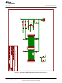
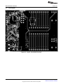
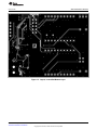
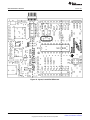
1
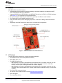
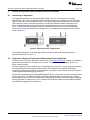
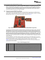
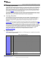
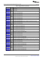
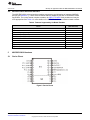
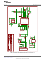
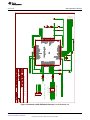
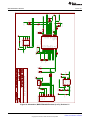
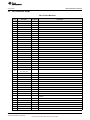
MSP-EXP430G2 LaunchPad Evaluation Kit
User's Guide
Literature Number: SLAU318F
July 2010 – Revised January 2015
Contents
1
MSP-EXP430G2 LaunchPad Overview .................................................................................... 4
.................................................................................................................. 4
1.2
Features ................................................................................................................... 5
1.3
Kit Contents ............................................................................................................... 5
1.4
Revisions .................................................................................................................. 6
2
Installation .......................................................................................................................... 6
2.1
Download the Required Software ...................................................................................... 6
2.2
Install the Software ....................................................................................................... 6
2.3
Install the Hardware...................................................................................................... 6
3
Getting Started With MSP-EXP430G2 LaunchPad..................................................................... 7
3.1
Getting Started ........................................................................................................... 7
3.2
Demo Application, Internal Temperature Measurement ............................................................ 7
4
Develop an Application With the MSP-EXP430G2 LaunchPad.................................................... 8
4.1
Developing an Application .............................................................................................. 8
4.2
Program and Debug the Temperature Measurement Demo Application ......................................... 8
4.3
Disconnect Emulator From Target With Jumper J3 ................................................................. 9
4.4
Program Connected eZ430 Target Boards.......................................................................... 10
4.5
Connecting a Crystal Oscillator ....................................................................................... 11
4.6
Connecting a BoosterPack ............................................................................................ 11
4.7
Supported Devices ..................................................................................................... 11
4.8
MSP-EXP430G2 On-Board Emulator ................................................................................ 13
5
MSP-EXP430G2 Hardware ................................................................................................... 13
5.1
Device Pinout ........................................................................................................... 13
5.2
Schematics .............................................................................................................. 14
5.3
PCB Layout .............................................................................................................. 20
5.4
Bill of Materials (BOM) ................................................................................................. 23
6
Suggested Reading ............................................................................................................ 24
7
Frequently Asked Questions (FAQ) ...................................................................................... 24
Revision History .......................................................................................................................... 26
1.1
2
Overview
Table of Contents
SLAU318F – July 2010 – Revised January 2015
Submit Documentation Feedback
Copyright © 2010–2015, Texas Instruments Incorporated
www.ti.com
List of Figures
1
MSP-EXP430G2 LaunchPad Overview................................................................................... 5
2
Insert Device Into Target Socket
3
4
5
6
7
8
9
10
11
12
13
14
.......................................................................................... 8
Code Composer Studio™ v4 in Debugging Mode ...................................................................... 9
MSP-EXP430G2 LaunchPad With Attached eZ430-RF2500 Target Board ........................................ 10
Device Pinout ............................................................................................................... 13
Schematics, MSP-EXP430G2 Emulator (1 of 2), Revision 1.4 ...................................................... 14
Schematics, MSP-EXP430G2 Emulator (2 of 2), Revision 1.4 ...................................................... 15
Schematics, MSP-EXP430G2 Target Socket, Revision 1.4 .......................................................... 16
Schematics, MSP-EXP430G2 Emulator (1 of 2), Revision 1.5 ...................................................... 17
Schematics, MSP-EXP430G2 Emulator (2 of 2), Revision 1.5 ...................................................... 18
Schematics, MSP-EXP430G2 Target Socket, Revision 1.5 .......................................................... 19
Layout, LaunchPad Top Layer ........................................................................................... 20
Layout, LaunchPad Bottom Layer........................................................................................ 21
Layout, LaunchPad Silkscreen ........................................................................................... 22
List of Tables
1
Jumper Connection J3 Between Emulator and Target ................................................................. 9
2
eZ430 Debugging Interface ............................................................................................... 10
3
Supported Devices ......................................................................................................... 11
4
Features Supported by On-Board Emulator ............................................................................ 13
5
Bill of Materials
.............................................................................................................
SLAU318F – July 2010 – Revised January 2015
Submit Documentation Feedback
Copyright © 2010–2015, Texas Instruments Incorporated
List of Figures
23
3
User's Guide
SLAU318F – July 2010 – Revised January 2015
MSP-EXP430G2 LaunchPad Evaluation Kit
Preface: Read This First
If You Need Assistance
If you have any feedback or questions, support for the MSP430™ devices and the MSP-EXP430G2 is
provided by the Texas Instruments Product Information Center (PIC) and the TI E2E Forum
(http://e2e.ti.com/). Contact information for the PIC can be found on the TI web site at http://support.ti.com.
Additional device-specific information can be found on the MSP430 web site at http://www.ti.com/msp430.
Related Documentation from Texas Instruments
The primary sources of MSP430 information are the device-specific data sheets and user's guides
available at the Texas Instruments MSP430 web site: http://www.ti.com/msp430.
MSP430 device user's guides, application reports, software examples and other MSP430 user's guides
can be found at the Tech Docs section. The CCS user's guide includes detailed information on setting up
a project and using Code Composer Studio™ for the MSP430 microcontroller (SLAU157).
Information specific to the MSP-EXP430G2 LaunchPad Evaluation Kit, all the available IDEs, Software
Libraries, and examples can be found at the Tools & Software section: http://www.ti.com/tool/mspexp430g2.
1
MSP-EXP430G2 LaunchPad Overview
1.1
Overview
The MSP-EXP430G2 LaunchPad is an inexpensive and simple evaluation kit for the MSP430G2xx Value
Line series of microcontrollers. It is an easy way to start developing on the MSP430 with on-board
emulation for programming and debugging as well as buttons and LEDs for a simple user interface.
Rapid prototyping is simplified by the 20-pin BoosterPack headers which support a wide range of available
BoosterPack plug-in modules. You can quickly add features like wireless connectivity, graphical displays,
environmental sensing, and much more. You can either design your own BoosterPack or choose among
many already available from TI and third party developers.
The LaunchPad features an integrated DIP target socket that supports up to 20 pins, allowing MSP430™
Value Line devices to be plugged into the LaunchPad board. The MSP-EXP430G2 LaunchPad comes
with an MSP430G2553 device by default. The MSP430G2553 has the most memory available of the
compatible Value Line devices.
The MSP430G2553 16-bit MCU has 16KB flash, 512 bytes RAM, up to 16-MHz CPU speed, 10-bit ADC,
capacitive touch enabled I/Os, universal serial communication interface, and more – plenty to get you
started in your development.
Free software development tools are also available: TI's Eclipse-based Code Composer Studio™ IDE
(CCS), IAR Embedded Workbench™ IDE (IAR), and the community-driven Energia open source code
editor. More information about the LaunchPad, including documentation and design files, can be found on
the tool page at http://www.ti.com/tool/msp-exp430g2.
MSP430, Code Composer Studio are trademarks of Texas Instruments.
IAR Embedded Workbench is a trademark of IAR Systems.
All other trademarks are the property of their respective owners.
4
MSP-EXP430G2 LaunchPad Evaluation Kit
SLAU318F – July 2010 – Revised January 2015
Submit Documentation Feedback
Copyright © 2010–2015, Texas Instruments Incorporated
MSP-EXP430G2 LaunchPad Overview
www.ti.com
1.2
Features
MSP-EXP430G2 LaunchPad features:
• USB debugging and programming interface featuring a driverless installation and application UART
serial communication with up to 9600 Baud
• Supports MSP430G2xx2, MSP430G2xx3, and MSP430F20xx devices in PDIP14 or PDIP20 packages
(see Section 4.7 for a complete list of supported devices)
• Two general-purpose digital I/O pins connected to green and red LEDs for visual feedback
• Two push button for user feedback and device reset
• Easily accessible device pins for debugging purposes or as socket for adding customized extension
boards
• High-quality 20-pin DIP socket for an easy plug-in or removal of the target device
Figure 1. MSP-EXP430G2 LaunchPad Overview
1.3
Kit Contents
The MSP-EXP430G2 evaluation kit includes the following hardware:
• LaunchPad emulator socket board (MSP-EXP430G2)
• Mini USB-B cable, 0.5 m
• Two MSP430 flash devices
– MSP430G2553: Low-power 16-bit MSP430 microcontroller with an 8-channel 10-bit ADC, on-chip
comparator, touch-sense enabled I/Os, universal serial communication interface, 16kB flash
memory, and 512 bytes of RAM (preloaded with a sample program)
– MSP430G2452: Low-power 16-bit MSP430 microcontroller with an 8-channel 10-bit ADC, on-chip
comparator, touch-sense enabled I/Os, universal serial interface, 8kB flash memory, and 256 bytes
of SRAM
• Two 10-pin PCB connectors female
• 32.768-kHz clock crystal from Micro Crystal (http://www.microcrystal.com)
• Quick start guide
• Two LaunchPad stickers
SLAU318F – July 2010 – Revised January 2015
Submit Documentation Feedback
MSP-EXP430G2 LaunchPad Evaluation Kit
Copyright © 2010–2015, Texas Instruments Incorporated
5
MSP-EXP430G2 LaunchPad Overview
1.4
www.ti.com
Revisions
The first production revision of the LaunchPad in 2010 was 1.3. In 2012 the LaunchPad board revision
changed from 1.4 to 1.5 to align with the new release of Value Line devices. The differences in the
schematic and the kit contents are:
• Layout and Schematic:
– Voltage feedback in the emulator changed to increase startup stability (Rev 1.3 to Rev 1.4)
– Rearranged jumper J3 to support two UART configurations: vertical (SW UART), horizontal (HW
UART)
– VCC on the connector J4 can now be disconnected from the emulator VCC by J3
– Pullup resistor R34 and capacitor C24 on P1.3 removed to reduce the current consumption
– Presoldered male headers J1 and J2
2
Installation
The MSP-EXP430G2 LaunchPad installation consists of three easy steps:
1. Download the required software.
2. Install the selected IDE.
3. Connect the LaunchPad to the PC.
Then the LaunchPad is ready to develop applications or to use the pre-programmed demo application.
2.1
Download the Required Software
Different development software tools are available for the MSP-EXP430G2 LaunchPad development
board. IAR Embedded Workbench™ KickStart IDE and Code Composer Studio™ (CCS) IDE are both
available in a free limited version. IAR Embedded Workbench allows 4KB of C-code compilation. CCS is
limited to a code size of 16KB. The software is available at http://www.ti.com/mspds. There are many
other compilers and integrated development environments (IDEs) available to use with the MSP-EXP430
LaunchPad including Rowley Crossworks and MSPGCC. However, example projects have been created
using IAR Embedded Workbench KickStart IDE and Code Composer Studio IDE (CCS). For more
information on the supported software and the latest code examples, visit the LaunchPad tool page
(http://www.ti.com/tool/msp-exp430g2).
2.2
Install the Software
Download one of the integrated development environments (IDEs) (see Section 2.1). IAR KickStart and
CCS offer the required driver support to work with the MSP-EXP430 LaunchPad onboard emulation. Once
installed, the IDE should find the MSP-EXP430G2 LaunchPad as USB:HID debugging interface. Now all is
set for developing MSP430G2xx based application on the LaunchPad.
2.3
Install the Hardware
Connect the MSP-EXP430G2 LaunchPad socket board with the enclosed USB cable to a PC. The driver
installation starts automatically. If prompted for software, allow Windows to install the software
automatically. This is possible only if either IAR KickStart or CCS is already installed.
6
MSP-EXP430G2 LaunchPad Evaluation Kit
SLAU318F – July 2010 – Revised January 2015
Submit Documentation Feedback
Copyright © 2010–2015, Texas Instruments Incorporated
Getting Started With MSP-EXP430G2 LaunchPad
www.ti.com
3
Getting Started With MSP-EXP430G2 LaunchPad
3.1
Getting Started
The first time the MSP-EXP430G2 LaunchPad Evaluation Kit is used, a demo application automatically
starts as soon as the board is powered from the USB host. To start the demo, connect the MSPEXP430G2 LaunchPad with the included mini USB cable to a free USB port. The demo application starts
with an LED toggle to show the device is active. More information about the demo application can be
found in Section 3.2.
3.2
Demo Application, Internal Temperature Measurement
The LaunchPad includes a pre-programmed MSP430G2553 device already installed in the target socket.
When LaunchPad is connected via USB, the demo starts with an LED toggle sequence. The onboard
emulation generates the supply voltage and all the signals necessary to start.
Press button P1.3 to switch the application to a temperature measurement mode. A reference temperature
is taken at the beginning of this mode, and the LEDs of the LaunchPad signal a rise or fall in temperature
by varying the brightness of the on-board red or green LED, respectively. The reference temperature can
also be recalibrated with another button press on P1.3. The collected temperature data is also
communicated via back-channel UART through the USB emulation circuitry back to the PC. The internal
temperature sensor data from the MSP430G2553 device is sent to the PC to be displayed on the GUI.
The pre-loaded demo application and the GUI are found in the Software Examples zip folder. The GUI is
opened with LaunchPad_Temp_GUI.exe. This GUI is made with Processing (http://processing.org) with
the source available for customization. The serial communication port on the PC must be configured with
2400 bps, one stop bit, and no flow control to display the values correctly.
The demo application uses the on-chip peripherals of the MSP430G2553 device such as the 10-bit ADC,
which samples the internal temperature sensor, and 16-bit timers, which drive the PWM to vary brightness
of the LEDs and enable software UART for communication with the PC. The MSP430G2553 offers a USCI
interface that is capable of communicating through UART at up to 2 MBaud, but to be aligned with all the
other MSP430G2xx devices, the demo uses the Timer UART implementation, which can be used on all
the other devices. This way the demo can be used with any other MSP430G2xx device with an integrated
ADC, without any change in the program.
The provided applications can be a great starting point for various custom applications and give a good
overview of the various applications of the MSP430G2xx Value Line devices.
SLAU318F – July 2010 – Revised January 2015
Submit Documentation Feedback
MSP-EXP430G2 LaunchPad Evaluation Kit
Copyright © 2010–2015, Texas Instruments Incorporated
7
Develop an Application With the MSP-EXP430G2 LaunchPad
www.ti.com
4
Develop an Application With the MSP-EXP430G2 LaunchPad
4.1
Developing an Application
The integrated development environments (IDEs) shown in Section 2 offer support for the whole
MSP430G2xx Value Line. The MSP-EXP430G2 LaunchPad needs only a connection to the USB of the
Host PC—there is no external hardware required. The power supply and the Spy-Bi-Wire JTAG signals
TEST and RST must be connected with jumper J3 to allow the onboard emulation connection to the
device. Now the preferred device can be plugged into the DIP target socket of the LaunchPad (see
Figure 2). Both PDIP14 and PDIP20 devices of the MSP430G2xx Value Line and the MSP430F20xx
family can be inserted into the DIP socket aligned to pin 1. A complete list of supported devices can be
found in Section 4.7.
Figure 2. Insert Device Into Target Socket
The following example for Code Composer Studio shows how to download and debug the demo
application described in Section 3.2.
4.2
Program and Debug the Temperature Measurement Demo Application
The source code of the demo application can be found in the Software Examples zip folder. Download the
project folder and unpack it to a location of your choice. For this demo, Code Composer Studio v4 or
newer must be installed.
The demo application can be loaded to the CCS workspace by clicking File→Import. Select the location of
the extracted project files and import Existing projects into Workspace. Now the MSP-EXP430G2Launchpad project appears inside the CCS workspace. The project must be marked as the active project
to start programming and debugging the device.
Connect the LaunchPad with an inserted MSP430G2553 device to the host PC and click the Debug button
on the CCS Toolbar. The MSP-EXP430G2 LaunchPad is initialized and the download of the compiled
demo application starts. The CCS view switches to a debugging interface once the download is completed
and the application is ready to start. Figure 3 shows Code Composer Studio v4 with the MSP-EXP430G2
LaunchPad demo application in debug view.
8
MSP-EXP430G2 LaunchPad Evaluation Kit
SLAU318F – July 2010 – Revised January 2015
Submit Documentation Feedback
Copyright © 2010–2015, Texas Instruments Incorporated
Develop an Application With the MSP-EXP430G2 LaunchPad
www.ti.com
Figure 3. Code Composer Studio™ v4 in Debugging Mode
4.3
Disconnect Emulator From Target With Jumper J3
The connection between the MSP-EXP430G2 emulator and the attached target device can be opened
with the jumper array J3. This can be useful to access an attached eZ430 target board by disconnecting
the Spi-Bi-Wire JTAG lines RST and TEST or if the JTAG lines are used for other application purposes.
The jumper array can also be used to measure the power consumption of the LaunchPad application. For
this intention, all connections except VCC must be opened, and a multi meter can used on the VCC
Jumper to measure the current of the MSP-EXP430G2 target device and its peripherals. The jumper J5
VCC also must be opened if the LaunchPad board is powered with an external power supply over J6
Table 1 or the eZ430 interface J4.
NOTE: The assignment of jumper J3 has been changed in MSP-EXP430G2 revision 1.5, see the
comments in Table 1 to find the assignment for a specific board revision.
Table 1. Jumper Connection J3 Between Emulator and Target
Jumper
Signal
1
VCC
Target socket power supply voltage (power consumption test jumper) (located on 5 before Rev. 1.5)
Description
2
TEST
Test mode for JTAG pins or Spy-Bi-Wire test clock input during programming and test (located on 1 before
Rev. 1.5)
3
RST
Reset or Spy-Bi-Wire test data input/output during programming and test (located on 2 before Rev. 1.5)
4
RXD
UART receive data input (direction can be selected by jumper orientation) (located on 3 before Rev. 1.5)
5
TXD
UART transmit data output (direction can be selected by jumper orientation) (located on 4 before Rev. 1.5)
Jumpers 4 and 5 connect the UART interface of the emulator to the target device pins P1.1 and P1.2.
These jumpers can be used to select between a software (SW) UART or a hardware (HW) UART by their
orientation. In vertical orientation (SW UART), the jumpers connect the emulation TXD signal to target
P1.2 and the emulation RXD signal to target P1.1, as they are used for the software UART communication
on the demo application (see Section 2.2). In horizontal orientation (HW UART), the jumpers connect the
SLAU318F – July 2010 – Revised January 2015
Submit Documentation Feedback
MSP-EXP430G2 LaunchPad Evaluation Kit
Copyright © 2010–2015, Texas Instruments Incorporated
9
Develop an Application With the MSP-EXP430G2 LaunchPad
www.ti.com
emulator TXD signal to target P1.1 and the emulator RXD to target P1.2, as required for the USCI module.
Keep in mind that UART communication is full duplex, so connections are made for both transmit and
receive on each side, and the labeling is specific to what action each side of the UART bus is performing.
For example, the emulator TXD (transmit) signal connects to the target RXD (receive) signal, and the
emulator RXD signal connects to the target TXD signal.
4.4
Program Connected eZ430 Target Boards
The MSP-EXP430G2 LaunchPad can program the eZ430-RF2500T target boards, the eZ430-Chronos
watch module, or the eZ430-F2012T/F2013T. To connect one of the ez430 targets, connector J4 must be
populated with a 0.050-in (1.27-mm) pitch male header, as shown in Figure 4.
Figure 4. MSP-EXP430G2 LaunchPad With Attached eZ430-RF2500 Target Board
To program the attached target without interfering with the LaunchPad socket board, jumper connections
TEST and RST of J3 must be open. The interface to the eZ430 target board is always connected to the
MSP-EXP430G2 emulator, so the programming and debugging of a connected LaunchPad target device
is possible only if the eZ430 target is not connected on the same time. The application UART, on the other
hand, is connected directly to the LaunchPad target device, and jumper J3 can be closed to monitor the
transmission from the LaunchPad target to the attached eZ430. This way both possible connections, from
the device to the PC and from the device to the eZ430, can be established without changing the direction
of the UART pins.
The VCC connection to the eZ430 interface is directly connected to the LaunchPad target VCC and can
be separated with jumper J3, if the LaunchPad itself should be powered via a connected battery on J4. To
supply the eZ430 interface with the onboard emulator the jumper J3 VCC needs to be closed.
Table 2 shows the pinout of the eZ430 debugging interface J4, the first pin is the left pin located on the
emulator part of the LaunchPad.
Table 2. eZ430 Debugging Interface
Pin
10
Signal
Description
1
TXD
UART transmit data output (UART communication from PC or MSP430G2xx to eZ430 target board)
2
VCC
Power supply voltage (J3 VCC needs to be closed to supply via onboard emulator)
3
TEST / SBWTCK
Test mode for JTAG pins and Spy-Bi-Wire test clock input during programming and test
4
RST / SBWTDIO
Reset, Spy-Bi-Wire test data input/output during programming and test
5
GND
Power supply ground
6
RXD
UART receive data input (UART communication from eZ430 target board to PC or MSP430G2xx)
MSP-EXP430G2 LaunchPad Evaluation Kit
SLAU318F – July 2010 – Revised January 2015
Submit Documentation Feedback
Copyright © 2010–2015, Texas Instruments Incorporated
Develop an Application With the MSP-EXP430G2 LaunchPad
www.ti.com
4.5
Connecting a Crystal Oscillator
The MSP-EXP430G2 LaunchPad offers a footprint for a variety of crystal oscillators. The XIN and XOUT
signals of the LFXT1 oscillator can support low-frequency oscillators like a watch crystals of 32768 Hz or a
standard crystal with a range defined in the associated data sheet. The signal lines XIN and XOUT can
also be used as multipurpose I/Os or as a digital frequency input. More information on the possibilities of
the low-frequency oscillator and the possible crystal selection can be found in the MSP430x2xx Family
User's Guide (SLAU144) or the device-specific data sheet.
The oscillator signals are connected to J2 to use the signals on an attached application board. In case of
signal distortion of the oscillator signals that leads to a fault indication at the basic clock module, resistors
R29 and R28 can be used to disconnect the pin header J2 from the oscillating lines.
4.6
Connecting a BoosterPack
The LaunchPad can connect to many BoosterPacks within the ecosystem. The BoosterPack headers J1
and J2 along with power supply J6 fall on a 100-mil (0.1-in) grid to allow for easy and inexpensive
development with a breadboard. The LaunchPad adheres to the 20-pin LaunchPad pinout standard. A
standard was created to aid compatibility between LaunchPads and BoosterPacks, across the TI
ecosystem.
The 20-pin standard is backward compatible with the 40-pin standard used by LaunchPads like the MSPEXP430F5529LP. This allows a subset of some 40-pin BoosterPacks to be used with 20-pin LaunchPads.
While most BoosterPacks are compliant with the standard, some are not. The LaunchPad is compatible
with all 20-pin (and 40-pin) BoosterPacks that are compliant with the standard. If the reseller or owner of
the BoosterPack does not explicitly indicate compatibility with the MSP430G2 LaunchPad, you might want
to compare the schematic of the candidate BoosterPack with the LaunchPad, to ensure compatibility.
Keep in mind that sometimes conflicts can be resolved by changing the G2 device pin function
configuration in software. More information about compatibility can also be found at
http://www.ti.com/launchpad.
4.7
Supported Devices
Texas Instruments offers several MSP430 devices in a PDIP package that is compatible with LaunchPad.
Table 3 shows the supported devices.
Table 3. Supported Devices
Part Number
Family
Description
MSP430F2001
F2xx
16-bit Ultra-Low-Power Microcontroller, 1KB Flash, 128B RAM, Comparator
MSP430F2002
F2xx
16-bit Ultra-Low-Power Microcontroller, 1KB Flash, 128B RAM, 10-Bit SAR A/D, USI for SPI/I2C
MSP430F2003
F2xx
16-bit Ultra-Low-Power Microcontroller, 1KB Flash, 128B RAM, 16-Bit Sigma-Delta A/D, USI for SPI/I2C
MSP430F2011
F2xx
16-bit Ultra-Low-Power Microcontroller, 2KB Flash, 128B RAM, Comparator
MSP430F2012
F2xx
16-bit Ultra-Low-Power Microcontroller, 2KB Flash, 128B RAM, 10-Bit SAR A/D, USI for SPI/I2C
MSP430F2013
F2xx
16-bit Ultra-Low-Power Microcontroller, 2KB Flash, 128B RAM, 16-Bit Sigma-Delta A/D, USI for SPI/I2C
MSP430G2001
G2xx
16-bit Ultra-Low-Power Microcontroller, 512B Flash, 128B RAM
MSP430G2101
G2xx
16-bit Ultra-Low-Power Microcontroller, 1KB Flash, 128B RAM
MSP430G2111
G2xx
16-bit Ultra-Low-Power Microcontroller, 1KB Flash, 128B RAM, Comparator
MSP430G2121
G2xx
16-bit Ultra-Low-Power Microcontroller, 1KB Flash, 128B RAM, USI for SPI/I2C
MSP430G2131
G2xx
16-bit Ultra-Low-Power Microcontroller, 1KB Flash, 128B RAM, 10-Bit SAR A/D, USI for SPI/I2C
MSP430G2201
G2xx
16-bit Ultra-Low-Power Microcontroller, 2KB Flash, 128B RAM
MSP430G2211
G2xx
16-bit Ultra-Low-Power Microcontroller, 2KB Flash, 128B RAM, Comparator
MSP430G2221
G2xx
16-bit Ultra-Low-Power Microcontroller, 2KB Flash, 128B RAM, USI for SPI/I2C
MSP430G2231
G2xx
16-bit Ultra-Low-Power Microcontroller, 2KB Flash, 128B RAM, 10-Bit SAR A/D, USI for SPI/I2C
MSP430G2102
G2xx
16-bit Ultra-Low-Power Microcontroller, 1KB Flash, 256B RAM, USI for SPI/I2C, 16 Capacitive-Touch
Enabled I/O Pins
MSP430G2202
G2xx
16-bit Ultra-Low-Power Microcontroller, 2KB Flash, 256B RAM, USI for SPI/I2C, 16 Capacitive-Touch
Enabled I/O Pins
SLAU318F – July 2010 – Revised January 2015
Submit Documentation Feedback
MSP-EXP430G2 LaunchPad Evaluation Kit
Copyright © 2010–2015, Texas Instruments Incorporated
11
Develop an Application With the MSP-EXP430G2 LaunchPad
www.ti.com
Table 3. Supported Devices (continued)
Part Number
12
Family
Description
MSP430G2302
G2xx
16-bit Ultra-Low-Power Microcontroller, 4KB Flash, 256B RAM, USI for SPI/I2C, 16 Capacitive-Touch
Enabled I/O Pins
MSP430G2402
G2xx
16-bit Ultra-Low-Power Microcontroller, 8KB Flash, 256B RAM, USI for SPI/I2C, 16 Capacitive-Touch
Enabled I/O Pins
MSP430G2112
G2xx
16-bit Ultra-Low-Power Microcontroller, 1KB Flash, 256B RAM, Comparator, USI for SPI/I2C,
16 Capacitive-Touch Enabled I/O Pins
MSP430G2212
G2xx
16-bit Ultra-Low-Power Microcontroller, 2KB Flash, 256B RAM, Comparator, USI for SPI/I2C,
16 Capacitive-Touch Enabled I/O Pins
MSP430G2312
G2xx
16-bit Ultra-Low-Power Microcontroller, 4KB Flash, 256B RAM, Comparator, USI for SPI/I2C,
16 Capacitive-Touch Enabled I/O Pins
MSP430G2412
G2xx
16-bit Ultra-Low-Power Microcontroller, 8KB Flash, 256B RAM, Comparator, USI for SPI/I2C,
16 Capacitive-Touch Enabled I/O Pins
MSP430G2132
G2xx
16-bit Ultra-Low-Power Microcontroller, 1KB Flash, 256B RAM, 10-Bit SAR A/D, USI for SPI/I2C,
16 Capacitive-Touch Enabled I/O Pins
MSP430G2232
G2xx
16-bit Ultra-Low-Power Microcontroller, 2KB Flash, 256B RAM, 10-Bit SAR A/D, USI for SPI/I2C,
16 Capacitive-Touch Enabled I/O Pins
MSP430G2332
G2xx
16-bit Ultra-Low-Power Microcontroller, 4KB Flash, 256B RAM, 10-Bit SAR A/D, USI for SPI/I2C,
16 Capacitive-Touch Enabled I/O Pins
MSP430G2432
G2xx
16-bit Ultra-Low-Power Microcontroller, 8KB Flash, 256B RAM, 10-Bit SAR A/D, USI for SPI/I2C,
16 Capacitive-Touch Enabled I/O Pins
MSP430G2152
G2xx
16-bit Ultra-Low-Power Microcontroller, 1KB Flash, 256B RAM, 10-Bit SAR A/D, Comparator, USI for
SPI/I2C, 16 Capacitive-Touch Enabled I/O Pins
MSP430G2252
G2xx
16-bit Ultra-Low-Power Microcontroller, 2KB Flash, 256B RAM, 10-Bit SAR A/D, Comparator, USI for
SPI/I2C, 16 Capacitive-Touch Enabled I/O Pins
MSP430G2352
G2xx
16-bit Ultra-Low-Power Microcontroller, 4KB Flash, 256B RAM, 10-Bit SAR A/D, Comparator, USI for
SPI/I2C, 16 Capacitive-Touch Enabled I/O Pins
MSP430G2452
G2xx
16-bit Ultra-Low-Power Microcontroller, 8KB Flash, 256B RAM, 10-Bit SAR A/D, Comparator, USI for
SPI/I2C, 16 Capacitive-Touch Enabled I/O Pins
MSP430G2153
G2xx
16-bit Ultra-Low-Power Microcontroller, 1KB Flash, 256B RAM, 10-Bit SAR A/D, Comparator, USCI for
I2C/SPI/UART, 24 Capacitive-Touch Enabled I/O Pins
MSP430G2203
G2xx
16-bit Ultra-Low-Power Microcontroller, 2KB Flash, 256B RAM, Comparator, USCI for I2C/SPI/UART,
24 Capacitive-Touch Enabled I/O Pins
MSP430G2313
G2xx
16-bit Ultra-Low-Power Microcontroller, 2KB Flash, 256B RAM, Comparator, USCI for I2C/SPI/UART,
24 Capacitive-Touch Enabled I/O Pins
MSP430G2333
G2xx
16-bit Ultra-Low-Power Microcontroller, 2KB Flash, 256B RAM, 10-Bit SAR A/D, Comparator, USCI for
I2C/SPI/UART, 24 Capacitive-Touch Enabled I/O Pins
MSP430G2353
G2xx
16-bit Ultra-Low-Power Microcontroller, 2KB Flash, 256B RAM, 10-Bit SAR A/D, Comparator, USCI for
I2C/SPI/UART, 24 Capacitive-Touch Enabled I/O Pins
MSP430G2403
G2xx
16-bit Ultra-Low-Power Microcontroller, 8KB Flash, 512B RAM,, Comparator, USCI for I2C/SPI/UART,
24 Capacitive-Touch Enabled I/O Pins
MSP430G2413
G2xx
16-bit Ultra-Low-Power Microcontroller, 8KB Flash, 512B RAM, Comparator, USCI for I2C/SPI/UART,
24 Capacitive-Touch Enabled I/O Pins
MSP430G2433
G2xx
16-bit Ultra-Low-Power Microcontroller, 8KB Flash, 512B RAM, 10-Bit SAR A/D, Comparator, USCI for
I2C/SPI/UART, 24 Capacitive-Touch Enabled I/O Pins
MSP430G2453
G2xx
16-bit Ultra-Low-Power Microcontroller, 8KB Flash, 512B RAM, 10-Bit SAR A/D, Comparator, USCI for
I2C/SPI/UART, 24 Capacitive-Touch Enabled I/O Pins
MSP430G2513
G2xx
16-bit Ultra-Low-Power Microcontroller, 16KB Flash, 512B RAM, Comparator, USCI for I2C/SPI/UART,
24 Capacitive-Touch Enabled I/O Pins
MSP430G2533
G2xx
16-bit Ultra-Low-Power Microcontroller, 16KB Flash, 512B RAM, 10-Bit SAR A/D, Comparator, USCI for
I2C/SPI/UART, 24 Capacitive-Touch Enabled I/O Pins
MSP430G2553
G2xx
16-bit Ultra-Low-Power Microcontroller, 16KB Flash, 512B RAM, 10-Bit SAR A/D, Comparator, USCI for
I2C/SPI/UART, 24 Capacitive-Touch Enabled I/O Pins
MSP-EXP430G2 LaunchPad Evaluation Kit
SLAU318F – July 2010 – Revised January 2015
Submit Documentation Feedback
Copyright © 2010–2015, Texas Instruments Incorporated
Develop an Application With the MSP-EXP430G2 LaunchPad
www.ti.com
4.8
MSP-EXP430G2 On-Board Emulator
The MSP-EXP430G2 on-board emulator enables programming and debugging of supported MSP430
devices (see Section 4.7). It offers several features that are enabled by a 2-wire JTAG interface called
Spy-Bi-Wire. For a more feature-complete emulator, the MSP-FET430UIF flash emulation tool may be
more appropriate. See Table 4 for more details on the MSP-EXP430G2 LaunchPad on-board emulator.
Table 4. Features Supported by On-Board Emulator
Support by LaunchPad
(MSP-EXP430G2)
Feature
✓
Supports MSP430F20xx, F21x2, F22xx, G2x01, G2x11, G2x21, G2x31, G2x53
Allows fuse blow
Adjustable target supply voltage
Fixed 2.8-V target supply voltage
✓
Fixed 3.6-V target supply voltage
4-wire JTAG
2-wire JTAG
✓
Application UART
✓
Supported by CCS
✓
Supported by IAR
✓
5
MSP-EXP430G2 Hardware
5.1
Device Pinout
Figure 5. Device Pinout
SLAU318F – July 2010 – Revised January 2015
Submit Documentation Feedback
MSP-EXP430G2 LaunchPad Evaluation Kit
Copyright © 2010–2015, Texas Instruments Incorporated
13
TP6TP4TP2
TP7TP5TP3TP1
GND
GND
GND
EZ_VBUS
RESET
C1
10n
RESET
R1 47k
C2
16p
EZ_VCC
C3
16p
Q1
12MHz
64
63
62
61
60
59
58
57
56
55
54
53
52
51
50
49
17
18
19
20
21
22
23
24
25
26
27
28
29
30
31
32
HTCK
HTMS
HTDI
HTDO
C5
100n
1
2
3
4
5
6
7
8
9
10
11
12
13
14
15
16
48
47
46
45
44
43
42
41
40
39
38
37
36
35
34
33
R2
47k
GND
R3
47k
RST3410
BRXDI
BTXDI
URXD
UTXD
R4
R5
R6
R7
100R
100R
100R
100R
J3
9
7
5
3
1
CLK3410
EZ_VCC
TEST/SBWTCK
RST/SBWTDIO
P1.2
P1.1
VCC
SBW & UART I/F to Argon
SBWTCK 10
SBWTDIO 8
6
BTXD
4
BRXD
EZ_VCC 2
1
2
3
4
5
6
SL127L6TH
J4
SBW & UART I/F to external Target
P1.1
EZ_VCC
SBWTCK
SBWTDIO
GND
P1.2
Removed U2: SN75240PW from SBW connections
Copyright © 2010–2015, Texas Instruments Incorporated
C4
1u/6.3V
EZ_VCC
R26
270
LED0
green
GND
URTS
UDTR
UDSR
UCTS
SCL
SDA
MSP-EXP430G2 EMULATOR 1/2
1.4
SLAU318F – July 2010 – Revised January 2015
Submit Documentation Feedback
MSP-EXP430G2 LaunchPad Evaluation Kit
14
Schematics
5.2
www.ti.com
MSP-EXP430G2 Hardware
Figure 6. Schematics, MSP-EXP430G2 Emulator (1 of 2), Revision 1.4
MSP-EXP430G2 Hardware
www.ti.com
RST3410
1u/6.3V
C8
EZ_VCC
R16
47k
GND
DNP
BRXDI
BTXDI
CLK3410
SCL
SDA
R10
10k
R11
15k
EZ_VCC
UTXD
URXD
R25
1k5
R23
100R
R17 DNP
47k
R24
1k5
EZ_VCC
R12
33k
D1
1N4148
R19
3k3
R22
3k3
GND
1
9
12
2
22
17
19
10
11
32
31
30
29
27
26
VREGEN
RESET
WAKEUP
SUSPEND
CLKOUT
U3
SCL
SDA
WC
E1
C13
100n
PUR
DP
DM
CTS
DSR
DCD
RI/CP
RTS
DTR
TEST0
TEST1
VCC
VCC1
VDD18
GND
GND1
GND2
C11
100n
6
5
8
7
CAT24FC32UI
VSS VCC
E2
E0
U5
TUSB3410VF
SIN
SOUT
4
3
2
1
SDA
SCL
P3.0
P3.1
P3.3
P3.4
X1
X2
GND
5
6
7
13
14
15
16
20
21
23
24
3
25
4
8
18
28
R13 1k5
GND
EZ_VCC
C12
100n
GND
UCTS
UDSR
URTS
UDTR
EZ_VCC
R18
100k/1%
R20
100k/1%
C9
22p
GND
EZ_VBUS
C7
100n
GND GND
R15 33R
R14 33R
C10
22p
GND
5
6
3
4
GND
U2
IN1 OUT1
IN2 OUT2
FB
GND RES
EN
8
7
1
2
TPS77301DGK
RESET
VCC = +3.6V
R8
61k5
R9
33k
EZ_VCC
C6
USB_MINI_B5
SHIELD4
SHIELD3
SHIELD2
SHIELD1
GND
ID
D+
D-
VBUS
Mini USB
Connector
U$2
1u/6.3V
GND
2
1
GND
EZ_D-
S4
S3
S2
S1
5
4
3
EZ_VBUS
R21
33k
EZ_D+
GND
MSP-EXP430G2 EMULATOR 2/2
1.4
Copyright © 2010–2015, Texas Instruments Incorporated
15
MSP-EXP430G2 LaunchPad Evaluation Kit
SLAU318F – July 2010 – Revised January 2015
Submit Documentation Feedback
4
2
5
3
1
GND
NC
IO2
IO1
VCC
Figure 7. Schematics, MSP-EXP430G2 Emulator (2 of 2), Revision 1.4
0R
R29
DNP
R28
XIN
VCC
GND
XOUT
P1.0
P1.6
J1
1
2
3
4
5
6
7
8
9
10
R34
47K
VCC
P1.0
P1.1
P1.2
P1.3
P1.4
P1.5
P2.0
P2.1
P2.2
20
19
18
17
16
15
14
13
12
11
S2
GND
P1.3
20
19
18
17
16
15
14
13
12
11
J2
MSP-EXP430G2 TARGET SOCKET
GND
XIN
XINR
XOUTR XOUT
TEST/SBWTCK
RST/SBWTDIO
P1.7
P1.6
P2.5
P2.4
P2.3
R27 GND
47K
1
2
1
2
RST/SBWTDIO
20 Pin Socket
IC1
1
2
3
4
5
6
7
8
9
10
Socket: TBD
Type: TBD
S1
Ext_PWR
J6
GND
C23
10uF/10V
C21
12pF
270R
0R
R32 J5-1
R33 J5-2
470R
C14
1nF
DNP
DNP
C22
12pF
LED1
green
LED2
red
GND
DNP
C24
100nF
1
2
3
GND
1
2
3
4
C20
100nF
QUARZ5
Q2
1.4
SLAU318F – July 2010 – Revised January 2015
Submit Documentation Feedback
MSP-EXP430G2 LaunchPad Evaluation Kit
16
www.ti.com
MSP-EXP430G2 Hardware
Figure 8. Schematics, MSP-EXP430G2 Target Socket, Revision 1.4
Copyright © 2010–2015, Texas Instruments Incorporated
MSP-EXP430G2 Hardware
www.ti.com
GND
GND
GND
EZ_VBUS
RESET
1
2
3
4
5
6
7
8
9
10
11
12
13
14
15
16
C1
10n
RESET
R1 47k
C2
16p
EZ_VCC
C3
16p
Q1
12MHz
64
63
62
61
60
59
58
57
56
55
54
53
52
51
50
49
17
18
19
20
21
22
23
24
25
26
27
28
29
30
31
32
HTCK
HTMS
HTDI
HTDO
C5
100n
URTS
UDTR
UDSR
UCTS
48
47
46
45
44
43
42
41
40
39
38
37
36
35
34
33
R2
47k
GND
R3
47k
RST3410
BRXDI
BTXDI
URXD
UTXD
SCL
SDA
R4
R5
R6
R7
100R
100R
100R
100R
CLK3410
EZ_VCC
VCC
TEST/SBWTCK
RST/SBWTDIO
P1.2
BRXD
SBW & UART I/F to Argon
9
7
5
3
1
1
2
3
4
5
6
SL127L6TH
J4
SBW & UART I/F to external Target
J3
changed on Rev 1.5
EZ_VCC 10
SBWTCK 8
SBWTDIO 6
4
BTXD
2
P1.1
BRXD
BTXD
P1.1
VCC
SBWTCK
SBWTDIO
GND
P1.2
MSP-EXP430G2 EMULATOR 1/2
1.5
Copyright © 2010–2015, Texas Instruments Incorporated
C4
1u/6.3V
EZ_VCC
R26
270
GND
LED0
green
17
MSP-EXP430G2 LaunchPad Evaluation Kit
SLAU318F – July 2010 – Revised January 2015
Submit Documentation Feedback
TP6TP4TP2
TP7TP5TP3TP1
Figure 9. Schematics, MSP-EXP430G2 Emulator (1 of 2), Revision 1.5
RST3410
1u/6.3V
C8
EZ_VCC
R16
47k
GND
DNP
BRXDI
BTXDI
CLK3410
SCL
SDA
R10
10k
R11
15k
R12
33k
D1
1N4148
R19
3k3
R22
3k3
GND
1
9
12
2
22
17
19
10
11
32
31
30
29
27
26
VREGEN
RESET
WAKEUP
SUSPEND
CLKOUT
U3
E1
SCL
SDA
WC
100n
PUR
DP
DM
CTS
DSR
DCD
RI/CP
RTS
DTR
TEST0
TEST1
VCC
VCC1
VDD18
GND
GND1
GND2
C11
100n
6
5
8
7
CAT24FC32UI
VSS VCC
E2
E0
U5
TUSB3410VF
SIN
SOUT
SDA
SCL
P3.0
P3.1
P3.3
P3.4
X1
X2
2
1
3
4
C13
5
6
7
13
14
15
16
20
21
23
24
3
25
4
8
18
28
R13 1k5
GND
EZ_VCC
C12
100n
GND
UCTS
UDSR
URTS
UDTR
EZ_VCC
R18
100k/1%
R20
100k/1%
C9
22p
GND
EZ_VBUS
C7
100n
GND GND
R15 33R
R14 33R
C10
22p
GND
5
6
4
3
GND
U2
IN1 OUT1
IN2 OUT2
EN
FB
GND RES
8
7
1
2
TPS77301DGK
RESET
VCC = +3.6V
R8
61k5
R9
30k
EZ_VCC
C6
USB_MINI_B5
SHIELD4
SHIELD3
SHIELD2
SHIELD1
GND
ID
D+
D-
VBUS
Mini USB
Connector
U$2
1u/6.3V
GND
2
1
GND
EZ_D-
S4
S3
S2
S1
5
4
3
EZ_VBUS
R21
33k
EZ_D+
GND
MSP-EXP430G2 EMULATOR 2/2
1.5
Copyright © 2010–2015, Texas Instruments Incorporated
EZ_VCC
UTXD
URXD
R25
1k5
R23
100R
R17 DNP
47k
R24
1k5
EZ_VCC
GND
4
2
5
3
1
GND
NC
IO2
IO1
VCC
SLAU318F – July 2010 – Revised January 2015
Submit Documentation Feedback
MSP-EXP430G2 LaunchPad Evaluation Kit
18
www.ti.com
MSP-EXP430G2 Hardware
Figure 10. Schematics, MSP-EXP430G2 Emulator (2 of 2), Revision 1.5
MSP-EXP430G2 Hardware
www.ti.com
R29
0R
DNP
R28
0R
R32 J5-1
270R
R33 J5-2
470R
XIN
VCC
GND
XOUT
P1.0
P1.6
J1
1
2
3
4
5
6
7
8
9
10
DNP
VCC
P1.0
P1.1
P1.2
P1.3
P1.4
P1.5
P2.0
P2.1
P2.2
R34
47K
GND
20
19
18
17
16
15
14
13
12
11
20 Pin Socket
IC1
1
2
3
4
5
6
7
8
9
10
Socket: TBD
Type: TBD
R27
47K
RST/SBWTDIO
GND
GND
XIN
XINR
XOUTR XOUT
TEST/SBWTCK
RST/SBWTDIO
P1.7
P1.6
P2.5
P2.4
P2.3
S1
GND
20
19
18
17
16
15
14
13
12
11
S2
P1.3
J2
MSP-EXP430G2 TARGET SOCKET
1.5
Copyright © 2010–2015, Texas Instruments Incorporated
2
1
2
1
Ext_PWR
J6
GND
C21
12pF
DNP
DNP
C22
12pF
LED1
green
LED2
red
C14
1nF
C23
10uF/10V
GND
C24
100nF
19
MSP-EXP430G2 LaunchPad Evaluation Kit
SLAU318F – July 2010 – Revised January 2015
Submit Documentation Feedback
1
2
3
4
C20
100nF
QUARZ5
Q2
1
2
3
Figure 11. Schematics, MSP-EXP430G2 Target Socket, Revision 1.5
MSP-EXP430G2 Hardware
5.3
www.ti.com
PCB Layout
Figure 12. Layout, LaunchPad Top Layer
20
MSP-EXP430G2 LaunchPad Evaluation Kit
SLAU318F – July 2010 – Revised January 2015
Submit Documentation Feedback
Copyright © 2010–2015, Texas Instruments Incorporated
MSP-EXP430G2 Hardware
www.ti.com
Figure 13. Layout, LaunchPad Bottom Layer
SLAU318F – July 2010 – Revised January 2015
Submit Documentation Feedback
MSP-EXP430G2 LaunchPad Evaluation Kit
Copyright © 2010–2015, Texas Instruments Incorporated
21
MSP-EXP430G2 Hardware
www.ti.com
Figure 14. Layout, LaunchPad Silkscreen
22
MSP-EXP430G2 LaunchPad Evaluation Kit
SLAU318F – July 2010 – Revised January 2015
Submit Documentation Feedback
Copyright © 2010–2015, Texas Instruments Incorporated
MSP-EXP430G2 Hardware
www.ti.com
5.4
Bill of Materials (BOM)
Table 5. Bill of Materials
Ref Name
Number
per Board
1
C2, C3
2
16pF 0402 (33 pF on Rev 1.3)
2
C9, C10
2
22pF 0402
3
C1
1
10nF 0402
4
C5, C7, C11, C12, C13
5
100nF 0402
5
C4, C6, C8
3
1µF, 6.3V 0604
6
D1
1
1N4148 MicroMELF
7
EZ_USB
1
Mini-USB connector
8
Q1
1
SMD oscillator 12 MHz
9
R1, R2, R3, R16, R17
3
47k 0402 (R16, R17 is not populated)
10
R8
1
61k5 0402 (6k8 in Rev 1.3 and prior)
11
R19, R22
2
3k3 0402
12
R9
1
30k 0402 (3k3 in Rev 1.3 and prior)
13
R12, R21
2
33k 0402
14
R4, R5, R6, R7, R23
5
100R 0402
15
R14, R15
2
33R 0402
16
R18, R20
2
100k 0402
17
R13, R24, R25
3
1k5 0402
18
R10
1
10k 0402
19
R11
1
15k 0402
20
U1
1
MSP430F1612IPMR
21
U4
1
TPD2E001DRLR
22
U3
1
TUSB3410VF
23
U2
1
TPS77301DGKR
24
U5
1
I2C EEPROM 128k (AT24C128-10TU-2.7)
25
TP1, TP2, TP3, TP4,
TP5, TP6, TP7
1
1nF, SMD 0603
Pos.
Description
26
C14
27
C21, C22
28
C23
1
10µF, 10 V, SMD 0805
29
C20, C24
1
100nF, SMD 0603 (C24 is not populated)
30
LED0, LED1
2
Green DIODE 0603
31
LED2
1
Red DIODE 0603
32
R34, R27
1
47k SMD 0603 (R34 is not populated)
33
R32, R26
2
270R SMD 0603
34
R33
1
470R SMD 0603
35
R28, R29
2
0R SMD 0603
36
IC1
1
DIP20 socket
37
Q2
38
J1, J2,
2
10-pin header, TH, 2.54mm male (female header included)
39
J3
1
2X05 pin header male
40
J4
41
J5
1
2x02 pin header male
42
J6
2
3-pin header, male, TH
43
S1, S2
2
Push button
12.5pF, SMD 0603 (not populated)
Clock crystal 32kHz (Micro Crystal MS3V-T1R 32.768kHz CL:12.5pF ±20ppm
included)
6 pin header male 1.28mm
SLAU318F – July 2010 – Revised January 2015
Submit Documentation Feedback
MSP-EXP430G2 LaunchPad Evaluation Kit
Copyright © 2010–2015, Texas Instruments Incorporated
23
Suggested Reading
6
www.ti.com
Suggested Reading
The primary sources of MSP430™ information are the device-specific data sheets and the family user's
guides. The most up-to-date versions of those documents can be found at the Texas Instruments MSP430
landing page.
For more information on CCS and IAR, download the latest version from http://www.ti.com/mspds and
read the included user's guides and documentation in the installation folder. Documents describing the
IAR tools (Workbench/C-SPY, the assembler, the C compiler, the linker, and the library) are located in
common\doc and 430\doc. All necessary CCS documents can be found in the msp430\doc folder in the
CCS installation path. The FET user's guide also includes detailed information on how to set up a project
for the MSP430 using IAR or CCS, and it is included in most of the IDE releases and on the TI MSP430
side.
7
Frequently Asked Questions (FAQ)
1. Can other programming tools like the MSP-FET430UIF interface the MSP-EXP430G2 LaunchPad
socket device?
The LaunchPad evaluation kit works with any programming tool that supports the 2-wire Spy-Bi-Wire
interface. Both the MSP430 USB FET (MSP-FET430UIF) and the Gang Programmer (MSP-GANG430)
support these devices, but the connection must be made directly to the dedicated Spy-Bi-Wire ports.
See MSP-FET430 Flash Emulation Tool User's Guide (SLAU138) for details on using MSP430 USB
FET and the Gang Programmer for a 2-wire Spy-Bi-Wire interface. Do not try to connect the standard
JTAG connector to the MSP-EXP430G2 pinheads, as this could result in damage to the attached
hardware.
2. Does the MSP-EXP430G2 support fuse blow?
The MSP-EXP430G2 LaunchPad evaluation kit onboard debugging interface lacks the JTAG security
fuse-blow capability. To ensure firmware security on devices going to production, the USB Flash
Emulation Tool or the Gang Production Programmer, which support the fuse-blow feature, are
recommended.
3. What versions of IAR Embedded Workbench and Code Composer Studio are supported?
The MSP-EXP430G2 LaunchPad hardware is supported by IAR Embedded Workbench KickStart
Version 6.00 or higher and Code Composer Studio v4 or higher. To download the IDE visit
http://www.ti.com/mspds.
4. What are the part numbers for the connectors between the LaunchPad emulator board and the other
eZ430 target boards?
Header: MALE CONN HEADER .050" 6POS PCB R/A (for example, Digi-Key: S9016E-06-ND)
Socket: FEMALE CONN HEADER .050" 6POS PCB R/A (for example, Digi-Key: S9010E-06-ND)
5. I am not able to select the MSP430 Application UART and cannot receive data.
Ensure that the Application UART driver is correctly installed. This is done by installing either IAR
Embedded Workbench or Code Composer Studio v4.
To determine if the driver is correctly installed:
a. Plug in the MSP-EXP430G2 LaunchPad with the included Mini USB cable.
b. Right click My Computer and select Properties.
c. Select the Hardware tab and click on Device Manager.
d. Under Ports (COM & LPT) should be an entry for "MSP430 Application UART (COM xx)".
If the entry is there, but no characters are received, reconnect the LaunchPad to the PC and restart the
application to reload the drivers. If the Application UART is not listed, install the driver by following the
instructions in Section 2.2.
If the application UART is installed but not receiving UART data, ensure that the jumpers on J3 are
configured for the proper UART communication. The two UART jumpers are configured vertically for a
software (SW) UART, and horizontally for a hardware (HW) UART. The application implementation and
J3 jumpers should match for UART data to be properly transmitted.
24
MSP-EXP430G2 LaunchPad Evaluation Kit
SLAU318F – July 2010 – Revised January 2015
Submit Documentation Feedback
Copyright © 2010–2015, Texas Instruments Incorporated
Frequently Asked Questions (FAQ)
www.ti.com
6. The device is not answering to any communication, JTAG or UART.
If you are experiencing difficulties in communicating to the attached MSP430 target device, even
though all the communication drivers for the MSP-EXP430G2 are loaded correctly, the emulator is
probably set to a wrong communication state. This can be fixed by reconnecting the LaunchPad
evaluation kit and restarting the communicating application. Also make sure that all the jumpers on J3
are connected properly between the emulator and the target device. On revision 1.5 and newer, the
orientation of the UART jumpers must align with the software implementation on the target device.
7. I soldered the 32-kHz crystal to the board and the oscillation is not starting.
The MSP430 driving capabilities for the low-frequency crystal is limited, because it is designed for lowpower applications. To ensure proper operation, the load on these pins must be as small as possible,
the matching capacitors (12.5 pF for 32.768 kHz) for the crystal must be soldered to the board, and the
resistors R28 and R29 must be removed. Measuring the frequency of the oscillation with an
oscilloscope typically disturbs the oscillation.
8. The power consumption of the board is much higher than specified in the device data sheet, or I am
not measuring a current at all.
The MSP430 device inside of the LaunchPad socket can be powered with an external power supply at
header J6 or J4. To measure the power consumption in this mode, the VCC jumper, usually used to
measure the power consumption, must be removed, and the current must be measured directly at the
power supply. If the jumper J3 is not removed, the emulator circuitry of the LaunchPad is powered as
well. Measuring the current consumption during a debug session is not possible, because the cross
current through the JTAG connection influences the measurement. The most accurate results are
achieved with all jumpers on J3 removed. If the measurement is still not matching the data sheet
parameters, make sure that the code is aligned with all the power saving recommendations on the web
site MSP430™ - The World's Lowest Power MCU.
LaunchPad revisions 1.3 and 1.4 come with R34 populated. The 47-kΩ resistor is used as a pullup for
the button S2. If the port P1.3 is driven to ground, as suggested to keep the power consumption down,
the pullup resistor generates an additional current of approximately 77 µA. To reduce the power
consumption, the port should stay in input mode or the resistor should be removed if button S2 is not
used. The internal pullup of the MSP430G2xx can be used instead.
SLAU318F – July 2010 – Revised January 2015
Submit Documentation Feedback
MSP-EXP430G2 LaunchPad Evaluation Kit
Copyright © 2010–2015, Texas Instruments Incorporated
25
Revision History
www.ti.com
Revision History
Changes from E Revision (March 2014) to F Revision ................................................................................................... Page
•
Corrected the description of jumper settings in the paragraph that starts "Jumpers 4 and 5 connect the UART
interface..." ................................................................................................................................. 9
NOTE: Page numbers for previous revisions may differ from page numbers in the current version.
26
Revision History
SLAU318F – July 2010 – Revised January 2015
Submit Documentation Feedback
Copyright © 2010–2015, Texas Instruments Incorporated
IMPORTANT NOTICE
Texas Instruments Incorporated and its subsidiaries (TI) reserve the right to make corrections, enhancements, improvements and other
changes to its semiconductor products and services per JESD46, latest issue, and to discontinue any product or service per JESD48, latest
issue. Buyers should obtain the latest relevant information before placing orders and should verify that such information is current and
complete. All semiconductor products (also referred to herein as “components”) are sold subject to TI’s terms and conditions of sale
supplied at the time of order acknowledgment.
TI warrants performance of its components to the specifications applicable at the time of sale, in accordance with the warranty in TI’s terms
and conditions of sale of semiconductor products. Testing and other quality control techniques are used to the extent TI deems necessary
to support this warranty. Except where mandated by applicable law, testing of all parameters of each component is not necessarily
performed.
TI assumes no liability for applications assistance or the design of Buyers’ products. Buyers are responsible for their products and
applications using TI components. To minimize the risks associated with Buyers’ products and applications, Buyers should provide
adequate design and operating safeguards.
TI does not warrant or represent that any license, either express or implied, is granted under any patent right, copyright, mask work right, or
other intellectual property right relating to any combination, machine, or process in which TI components or services are used. Information
published by TI regarding third-party products or services does not constitute a license to use such products or services or a warranty or
endorsement thereof. Use of such information may require a license from a third party under the patents or other intellectual property of the
third party, or a license from TI under the patents or other intellectual property of TI.
Reproduction of significant portions of TI information in TI data books or data sheets is permissible only if reproduction is without alteration
and is accompanied by all associated warranties, conditions, limitations, and notices. TI is not responsible or liable for such altered
documentation. Information of third parties may be subject to additional restrictions.
Resale of TI components or services with statements different from or beyond the parameters stated by TI for that component or service
voids all express and any implied warranties for the associated TI component or service and is an unfair and deceptive business practice.
TI is not responsible or liable for any such statements.
Buyer acknowledges and agrees that it is solely responsible for compliance with all legal, regulatory and safety-related requirements
concerning its products, and any use of TI components in its applications, notwithstanding any applications-related information or support
that may be provided by TI. Buyer represents and agrees that it has all the necessary expertise to create and implement safeguards which
anticipate dangerous consequences of failures, monitor failures and their consequences, lessen the likelihood of failures that might cause
harm and take appropriate remedial actions. Buyer will fully indemnify TI and its representatives against any damages arising out of the use
of any TI components in safety-critical applications.
In some cases, TI components may be promoted specifically to facilitate safety-related applications. With such components, TI’s goal is to
help enable customers to design and create their own end-product solutions that meet applicable functional safety standards and
requirements. Nonetheless, such components are subject to these terms.
No TI components are authorized for use in FDA Class III (or similar life-critical medical equipment) unless authorized officers of the parties
have executed a special agreement specifically governing such use.
Only those TI components which TI has specifically designated as military grade or “enhanced plastic” are designed and intended for use in
military/aerospace applications or environments. Buyer acknowledges and agrees that any military or aerospace use of TI components
which have not been so designated is solely at the Buyer's risk, and that Buyer is solely responsible for compliance with all legal and
regulatory requirements in connection with such use.
TI has specifically designated certain components as meeting ISO/TS16949 requirements, mainly for automotive use. In any case of use of
non-designated products, TI will not be responsible for any failure to meet ISO/TS16949.
Products
Applications
Audio
www.ti.com/audio
Automotive and Transportation
www.ti.com/automotive
Amplifiers
amplifier.ti.com
Communications and Telecom
www.ti.com/communications
Data Converters
dataconverter.ti.com
Computers and Peripherals
www.ti.com/computers
DLP® Products
www.dlp.com
Consumer Electronics
www.ti.com/consumer-apps
DSP
dsp.ti.com
Energy and Lighting
www.ti.com/energy
Clocks and Timers
www.ti.com/clocks
Industrial
www.ti.com/industrial
Interface
interface.ti.com
Medical
www.ti.com/medical
Logic
logic.ti.com
Security
www.ti.com/security
Power Mgmt
power.ti.com
Space, Avionics and Defense
www.ti.com/space-avionics-defense
Microcontrollers
microcontroller.ti.com
Video and Imaging
www.ti.com/video
RFID
www.ti-rfid.com
OMAP Applications Processors
www.ti.com/omap
TI E2E Community
e2e.ti.com
Wireless Connectivity
www.ti.com/wirelessconnectivity
Mailing Address: Texas Instruments, Post Office Box 655303, Dallas, Texas 75265
Copyright © 2015, Texas Instruments Incorporated