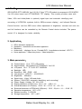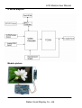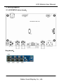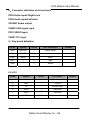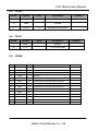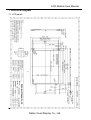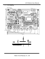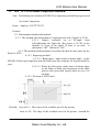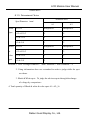
1
LCD MODULE SPECIFICATIONS
GD121MTLD-GTT104SDH01
Good Display
SPEC NO
REV NO
Good Display
Specifications
Type:
Model No.
Description:
Prepared:
Checked:
Approved:
Issue Date:
Standard
GD121MTLD-GTT104SDH01
10.4”, 800 x600dots,
TFT LCD module.
With white LED backlight
VGA and VIDEO input.
Xiaoli Lan
Moon Wu
Boris Jen
2009.06.18
Dalian Good Display Co., Ltd.
Good Display
No.17 Gonghua Street, Shahekou District, Dalian 116021 China
Tel: +86-411-84619565 Fax: +86-411-84619585
E-mail: [email protected]
Website: www.good-lcd.com
www.good-lcd.com.cn
Dalian Good Display Co., Ltd.
1.00
LCD Module User Manual
Catalogue
Content
2
Version
3
1. Profile
4
2. Application
4
3. Main parameter
4
4.Block diagram& picture
5
5. Wiring diagram
6
6. Connector definition of driver board
7-8
7. Structural diagram
9-10
8. 10.4"TFT- LCD PANEL Inspection standard
11-12
9. Packing
13
10. Precaution
13
Dalian Good Display Co., Ltd.
LCD Module User Manual
Version
Date
Version
Content
18th,june,09
VER:1.00
The first version
Dalian Good Display Co., Ltd.
LCD Module User Manual
1. Profile:
GD121MTLD-GTT104SDH01 Ver:1.00 10.4" Color TFT LCD module is composed of JD121MTLD
Ver:1.00 driver board and GTT104SDH01 TFT display. This module provides users with
Video, VGA and Audio(Audio is optional) signal input and automatic identifying and
converting of NTSC/PAL systems, built-in OSD(on-screen display)
and Infrared Remote
Control function. and the OSD menu offers adjustment of brightness, contrast and color etc,
and full functions can be controlled by the Remote Control device included. The power
control IC is designed for better reliability.
2. Application:
●
●
●
●
●
Office electronic equipment
Apparatus、Instrument and measure appliance
Machinery
Audiovisual (displayer for car、Portable DVD、Long-distance terminal、LCD TV)
Home appliance(Video door phone、Video telephone)
3. Main parameter:
z
z
z
z
z
z
z
z
z
z
z
z
z
z
z
z
Product Name:10.4"TFT LCD module
Module Model:GD121MTLD-GTT104SDH01 Ver:1.00
LCD panel:10.4"TFT LCD: GTT104SDH01
Backlight:LED
Resolution:800(RGB)×600
View angle Ø(U/D/L/R):(45/65/65/65)
Brightness: 400cd/m2
Signal input:Video, VGA and Audio
System:PAL/NTSC( automatic identifying and converting)
Power Supply Voltage:DC 12V±25%
Display dimension of LCD (mm):211.2(W)×158.4(H)
Overall dimension of LCD(mm):236.0(W)×176.9(H)×5.6(D)
Structural dimension of PCBA with VGA(mm):132.2(W)×89.9(H)×15.40(D)
Operation temperature:-20℃~+70℃
Relative humidity:5~95% RH
Storage temperature:-30℃~+80℃
Dalian Good Display Co., Ltd.
LCD Module User Manual
4. Block diagram:
Module picture
Dalian Good Display Co., Ltd.
LCD Module User Manual
5. Wiring diagram
5.1 JD121MTLD driver board:
Key-board:
Dalian Good Display Co., Ltd.
LCD Module User Manual
6、Connector definition of driver board
P203 Audio input /Right track
P202 Audio input/Left track
CN15B1 Audio output
CN202 VGA signal input
P201 VIDEO input
CN201 Y/C input
6.1 Key board definition
Pin No.
Symbol
In/Out
J201 description
SW4
SOURCE
I
Signal switch
SW5
POWER
I
Power
SW6
MENU
I
Menu
SW7
+
I
add
SW8
-
I
Minus
Remark
6.2 J301
Pin No.
Symbol
In/Out
Description
1
+5
O
+5 power output
2
GND
-
Ground
3
IR
-
Remote input
4
SAR0
I
Key input
5
SAR1
I
Key input
6
LED
O
LED indicator output
Dalian Good Display Co., Ltd.
Remark
LCD Module User Manual
6.3
CN102
Pin No.
Symbol
In/Out
Description
1
+12V
O
+12V output
2
GND
-
Ground
3
ON/0FF
O
Backlight on/off control
6.4
Remark
CN101
Pin No.
Symbol
In/Out
Description
1
GND
-
Ground
2
+12V
I
+12V Power input
6.5
JP402
No
1
Symbol
I/O
VDD
O
Description
Power Supply
2
VDD
O
Power Supply
3
GND
-
Ground
4
GND
-
Ground
5
IN0-
O
LVDS receiver negative signal channel 0
6
IN0+
O
LVDS receiver positive signal channel 0
7
IN1-
O
LVDS receiver negative signal channel 1
8
IN1+
O
LVDS receiver positive signal channel 1
9
IN2-
O
LVDS receiver negative signal channel 2
10
IN2+
OI
LVDS receiver positive signal channel 2
11
CLK-
O
LVDS receiver negative signal clock
12
CLK+
O
LVDS receiver positive signal clock
13
NC
14
NC
Dalian Good Display Co., Ltd.
Remark
Comment
LCD Module User Manual
7. Structural diagram
7.1 LCD panel:
Dalian Good Display Co., Ltd.
LCD Module User Manual
7.2
PCB diagram:
Dalian Good Display Co., Ltd.
LCD Module User Manual
8.
10.4" TFT- LCD PANEL Inspection standard:
Aim:Establishing the standard of PANLE for inspecting material & progress and
for clients’ inspection.
Scope:Apply to 10.4″TFT LCD
Content:
8.1. Determinant standard and method:
8.1.1. The method and determinant of inspecting the nick of panel of LCD:
8.1.1.1. Inspect vertically (or at 45°angle from
left/right)under the light tube (the power is 20 W) in the
distance of 30cm to the panel. If there is no nick , it
determines “OK”. Otherwise “NG”.
8.1.2. The method and determinative for black & white & color spots for the
Panel of LCD:
8.1.2.1. Inspecting method
8.1.2.1.1. Black spots:under status of denote light,set the
MASK of black spot inspection near the black spot then compare the big and small by
eyes.
8.1.2.1.2. White & Color spots: under status of denote light,
set the Mask of black spot inspection on the white
spot(or color spot) then inspect them by eyes if it
can hide.
8.1.2.2. Division of LCD Panel:
Remark:Area of A1:The center of the available area for the picture
Area of A2:The edge of the available area for the picture(around the
Dalian Good Display Co., Ltd.
LCD Module User Manual
central area)
8.1.3. Determinant Choice
Allowed Area
Spot Diameter(mm)
A1
A2
Black d≤0.15
Irrespective
Irrespective
Spot
0.15<d≤0.3
4
4
0.3<d≤0.5
2
3
0.5<d<0.8
0
2
White d≤0.15
Irrespective
Irrespective
or
0.15<d≤0.3
3
3
color
0.3<d≤0.5
1
2
spot
0.3<d<0.8
0
1
Remark: 1. Size: Average Diameter=(Max. Diameter + Min. Diameter)/2
2. Using information above as a standard in order to judge while the spot
are dense.
3. Black & White spot:To judge the obvious spots through the change
of voltage by comparison。
4. Total quantity of Black & white & color spot: A1+A2 ≤ 4。
Dalian Good Display Co., Ltd.
LCD Module User Manual
9. Packing
TBD
10. Precaution:
1、The
voltage of supply power don't exceed maxmium limit.
2. The connector can’t connect board in reverse, or the board will be burnt and the
products can't funtion well.
3. Please don’t touch it in order to keep your skin non-burn when you electrify the
board (there is High voltage on the board).
4. 10.4” TFT LCD Panel, it is a electric product, so you need to take anti-static
measure when you operate it.
5. 10.4” TFT- LCD Panel is a glasswork, place carefully, broken for fear.
6. The connection if “FPC”, which connect 10.4” Panel to PCBA, Please operate it
carefully in order to keep it well.
7. Don't touch the pin of "variable resistor" when you adjust "VR".
Dalian Good Display Co., Ltd.