1
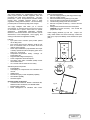
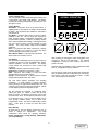
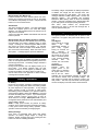
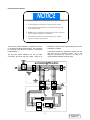
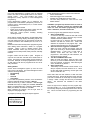
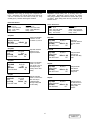
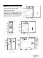
Use the following Modem Mode configuration screen to
control modem operations:
The event code(s) alarm description also display. Then
the message ”Press any key to enter terminal mode...”
displays again. Press a key to enter terminal mode, and
show the LCD display as described earlier in Terminal
Operation. If no keys are pressed for 45 seconds, the
UPS hangs up.
Modem Mode: IN
1-(000) 000-0000
Site ID:
Your Location
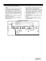
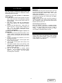
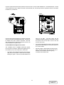
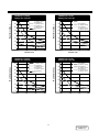
RS-232 with User-Configurable Relays - VCR232C
This provides user-selected contact closure output on the
RS-232 board, for use with remote monitoring devices.
The board also includes two relays. Program these relays
as NO or NC to activate upon any combination of these
alarms:
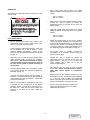
UPS on Battery
Low Battery
UPS on Bypass
Battery Test Fail
UPS Fail Overload
The options of the first line of this screen are IN, OUT,
BOTH, or OFF. IN calls are from a remote terminal
operator to the UPS. OUT calls are alarms reported from
the UPS to a selected phone number with a modem
attached. BOTH enables both IN and OUT calls. OFF
disables modem connections, but a directly connected
computer terminal may still be used.
The second line allows entry of the phone number the
UPS calls when alarms occur. Remember to include a 9
or other characters if required. When initiating a call, the
UPS makes up to 3 attempts to connect, spaced 45 to 90
seconds apart, before giving up.
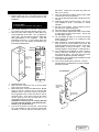
These relay outputs use an RJ45 connector. Connector
and 25’ pigtail supplied. Program the relays via the UPS
LCD display on the front panel.
Enter the Site ID on the fourth line. The UPS includes
Site ID in OUT messages to distinguish multiple UPS’s
programmed to call the same phone number. Use up to
16 characters (letters, numbers, and spaces) for the Site
ID.
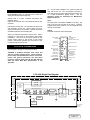
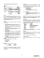
Cables
•
An optional factory-assembled 6-foot cable enables
connection to a modem.
•
A factory-assembled splitter cable enables connection
to a modem (or terminal) and a Computer/LAN
interface.
•
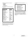
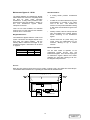
To assemble a customer supplied cable, refer to the
following instructions and Figure #5:
•
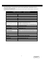
For a modem cable, connect to pins 2, 3, 7, 8, 20, and
22. Connect Pin 2 on one end to pin 3 on the other
end (this applies to two wires). All other connections
are straight through.
For a terminal cable (direct connection, no modem)
connect to pins 2, 3, and 7. All connections are straight
through.
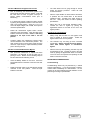
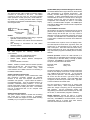
For terminal IN calls, the screen displays ”Press <SPACE
BAR> to enter terminal mode...”. Use the keyboard to get
information from the UPS or to perform remote ON, OFF,
or Transfer as described above. If no keys are pressed for
6 minutes, the UPS hangs up.
For UPS OUT calls, the receiving terminal beeps and
displays the message ”Press any key to enter terminal
mode...”. If no key is pressed within 10 seconds, the
terminal displays present alarm condition(s) information
along with the Site ID. The time of each alarm displays to
the nearest tenth of a second.
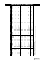
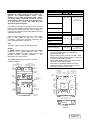
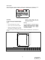
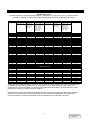
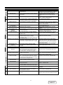
Signal Ground
Not Used
Not Used
Not Used
TXD
RXD
Not Used
Data Carrier Detect (DCD)
Low Battery Common
Low Battery (NC)
Low Battery (NO)
Shutdown Active Low
Power Fail
Active High
13 12 11 10
9
8
7
6
5
4
3
2
1
25 24 23 22 21 20 19 18 17 16 15 14
Altos Tri-Level
On Bypass
Low Battery Active High
Not Used
On UPS (NO)
On Battery (NO)
Common for On Battery,
On UPS, and On Bypass
On Battery (NC)
Data Terminal Ready (DTD)
Shutdown Active High
Not Used
Ring Indicator (R)
29
DISCONTINUED
PRODUCT