1
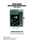
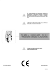
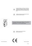
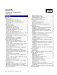
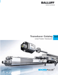
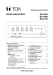
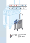
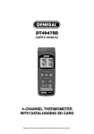
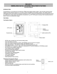
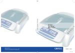
Pool-2000
Installation and Operating Manual
Always wear personal protective
equipment such as gloves and safety
glasses when working with
potentially hazardous chemicals.
Caution—Refer to accompanying
documents.
Caution—Risk of electric shock
Electrical installation of this
equpment should only be performed
by trained personnel in accordance
with local electrical wiring regulations
(in North America, refer to NEC and
CSA, C22.2 CEC Part 1). Before
working with this equipment, isolate
it from any electrical source and lock
out/tag out.
DR2000MF01
Figure 1a. Pool-2000
PREFACE
This manual describes how to install, setup, operate and
maintain the Pool-2000. Material in this manual is subject to
change without notice. Manual revisions will be made on an as
needed basis. Special circumstances involving important design,
operation or application information will be released via
Equipment Technical Bulletins.
A circuit breaker must be included in
the installation’s building. It must be
installed in close proximity to the
equipment and within easy reach of
the operator, and it must be marked
as the disconnecting device for the
equipment.
© Copyright 2009 Beta Technology, Inc.
SAFETY
Additional documentation for Pool
2000 units can be found at:
http://www.beta-technology.com.
These symbols on the unit mean:
If equipment is used in a manner not
specified by the manufacturer, the
protection provided may be impaired.
Direct Current
Alternating Current
SPECIFICATIONS
INTRODUCTION
OPERATING CONDITIONS
The Pool-2000 is a time-activated water-resistant peristaltic
pump for industrial applications. Up to 24 events may be
programmed with variable run times for each event from one
second to 19 minutes and 50 seconds. The Pool-2000 operates a
7-day clock in which events can be programmed to occur every
day or only on particular days throughout the week. A back up
battery keeps the clock running in the event of an interruption in
the electrical power.
Ambient Operating Temperature
5 to 40ºC (41 to 104ºF)
Electrical Power
115V~ 50/60 Hz 0.1A or 230V~ 50/60 Hz
Voltage fluctuations up to +/- 10% of nominal voltage.
Altitude
Max operating altitude 2000 meters (6500 feet)
Humidity
Max relative humidity 80% for temperatures up to 31ºC
(87.8ºF), decreasing linearly to 50% relative humidity at 40ºC
(104ºF).
Ratings
Intended for indoor or outdoor use (CSA approved for indoor
use only).
Pool-2000 (R16871-00 Rev C) December 2009
1210735
1
TIMING CAPABILITY
INSTALLATION
Up to 24 different times per period. Daily, weekly, or mixed
schedule; variable run time 1 second to 19 minutes and 59
seconds.
Refer installation and service to qualified
personnel only.
Installation must comply with all applicable
plumbing and electrical codes.
DIMENSIONS
Size
Inches
Height
5.6
Centimeters
Width* Depth**
4.6
4.8
14.2
11.6
Disconnect power from circulation system
before replacing tubing.
12.2
INSTALLING THE TUBING INTO
THE PUMP CARTRIDGES
*Width includes feet
**Depth with SnapHead pump cartridge in place.
Weight
The Pool-2000 comes with the pump cartridges affixed to it
without tubing. Following these instruction for installing the
tubing into the pump cartridge.
1.85 lbs/0.84 kg
Volume Per Day Output
1.
Flex Tube 0.125”ID: 9.0 GPD/34 liters LPD at
30 psi/2.07 bar
Make sure the Pool-2000 is powered off.
Roller
Assembly
COMPONENTS
Enclosure
Snap Pins
Molded ABS plastic, water-resistant, flame-resistant
Pump
Tube
Pump
Tie Wrap
Tube
Insert
Peristaltic, self-priming and self-checking,
6 Volts DC
Speed & Displacement
DR2000MF09
100 rpm, 2.5 oz per minute at 30/74 milliliters
30 psi/2.07 bar nominal*
Figure 1b. SnapHead Pump Cartridge
Max duty cycle 19 min. 59 sec ON, 20 min. OFF.
2.
Turn the SnapHead pins to the left or right to remove the
pump head.
3.
Loosen but do not remove the small screw at the bottom of
the rear cover and lift the cover from the cartridge.
4.
Coat the inside radius of the pump cartridge (the part that
comes in contact with the tubing) with Dow Corning III
lubricant.
Tubing Material
5.
Place the squeeze tube inside the pump cartridge.
Flex
6.
Press the two tube inserts into the cartridge so that the tie
wrap "buckles" face toward the center of the pump. The
tube must not be twisted during the assembly.
7.
Replace the rear cover and tighten the scew.
8.
Push the black SnapHead pins back into position, with the
arrow pointing up or down.
*Actual values may vary depending on operating conditions. We
recommend that you test output at startup and at regular
intervals for optimum performance,
Hydraulic Performance
Maximum Vacuum: 12 in of mercury
Maximum Pressure: 30 psi
Coin Battery
3 Volt Lithium BR2032 or CR2032 – See OFF-SEASON
STORAGE INSTRUCTIONS—PRESERVING PCB
BATTERY LIFE AND PROGRAMMING DATA in the
MAINTENANCE section for instructions on preserving battery
power and storing the unit during the off-season.
Regulatory
CE
Pool-2000
NSF50
CSA
115V only
For confirmation of regulatory compliance, see rating label on
your Pool-2000.
2
1210735
MOUNTING
The Pool-2000 should be mounted so the LCD screen can be
viewed easily. It should be located close enough to both the
injection point and liquid supply to ensure unobstructed
delivery.
1.
Align the metal mounting bracket and mount on a smooth
surface using screws.
2.
Place the Pool-2000 over the mounting bracket and slide it
down tight.
Pool-2000 (R16871-00 Rev C) December 2009
3.
If desired, a screw can be placed in one of the feet to hold
the unit in place.
The Pool-2000 can also be mounted using
the three plastic feet. If mounting on an
uneven surface, be careful not to over-tighten
or snap the feet off.
Figure 2. Pool-2000 Full Installation
INSTALLING SUPPLY LINES
Cut the desired length of 1/4-inch (6mm) chemical feed
line and attach it to the nut of the left side (suction side) of
the pump squeeze tube.
DR2000
MF03
1.
Figure 3. Installing the Chemical Feed Line to the
Squeeze Tube Fitting.
Pool-2000 (R16871-00 Rev C) December 2009
1210735
3
2.
For the chemical uptake side, a standpipe is provided. Cut
the bottom of the chemical feed line tubing at a 45-degree
angle and press it into the standpipe. Insert the chemical
feed line 0.5 inches (12 mm) above the bottom of the
standpipe. Both the 45-degree cut and the 0.5 inch (12 mm)
distance above the bottom of the standpipe will help avoid
the formation of a seal with the bottom of the chemical
drum and ensure an unobstructed chemical uptake.
DR2000MF02
CUT AT A
45° ANGLE
Figure 6. Plugging Pool-2000 into Outlet.
"
0. 5
DR2000MF04
Figure 4. Cutting Chemical Feed Tubing,
Inserting into Standpipe
DR2000MF05
Figure 5. Chemical Feed Tubing (uptake side) with Standpipe in
Chemical Drum
3.
Cut and connect the desired length of chemical feed line for
the chemical delivery to the right side of the pump squeeze
tube. Run the delivery tube to the desired injection point.
POWER SUPPLY
Dispenser power should be interlocked with
circulation power supply.
This unit comes with a standard power cord. No ground
connection is required.
4
1210735
Pool-2000 (R16871-00 Rev C) December 2009
SETTING THE CLOCK
A 15 amp branch circuit protection (circuit
breaker) must be included in the building’s
electrical installation. It must be installed in
close proximity and within easy reach of the
Pool-2000 operator. The circuit breaker must
be marked as the disconnecting device for
the Pool-2000. If the equipment is used in a
manner not specified by the manufacturer,
the protection provided may be impaired.
Once you enter Program Mode, your first option is to set the
clock. Use the Hours button and the Minutes button to change
the time of day. The clock will display “P” for PM settings. Use
the day button to change the day of the week. We recommend
that you program Monday as day 1.
PROGRAMMING WHEN AN EVENT
WILL OCCUR
OPTIONAL LOW LEVEL ALARM KIT
1.
An optional low level (sonic) alarm and low level alarm lance
are available (see Spare Parts list).
The low level alarm lance is inserted into the chemical drum and
the sonic alarm is installed on the left side of the pump housing.
Both are wired into the appropriate connectors on the main PCB.
The lance detects when the chemical drum is empty and the
sonic alarm issues an audible alarm.
Press the Event button once. You will see the following
screen. This screen indicates which event you are entering.
Example:
E:01
Refer to the installation instructions in the low level alarm kit
for more detailed instructions.
DR1000M04
The screen above indicates that you are entering event
number 1.
SETUP & PROGRAMMING
During normal operation, the Pool-2000 is in Run Mode. In Run
Mode, the screen will display the current time and day of the
week, and the colon will blink once per second.
The Pool-2000 is programmed using the 5 buttons and screen in
the front of the unit.
PROGRAM
2.
Press the Event button again. This screen shows the day
and time this event will begin.
3.
Change the time that the event will occur using the Hours
and Minutes buttons.
4.
Change the day of the week that this event will occur using
the day button. When scrolling through the day menus you
will see that you are able to select from the following
options:
•
Select each day individually, as days 1 through 7.
•
Select all the days of the week, 1 through 7 appear
together.
•
Select week day only, 1 through 5 appear together
•
Select weekend days only, 6 and 7 appear together
EVENT/PRIME
HOUR
MINUTES
Example:
SECONDS/DAY
1
1:45
DR2000MF06
P
DR2000MS03
Figure 8. Pool-2000, Front Plate
The screen above indicates that the event will occur at 1:45 PM
every Monday (only Mondays).
ENTERING PROGRAM MODE
Example:
To begin programming, you must first enter into Program Mode.
To do this, hold down the Program button for 8 seconds. The
colon will blink fast and irregularly while the Program button is
pressed.
The screen will flash and the colon will stop blinking to indicate
that you have successfully entered Program Mode. The screen
display will not change. It will continue to show the current time
and day of the week.
Pool-2000 (R16871-00 Rev C) December 2009
1210735
1234567
8:30
DR2000MS07
The screen above indicates that the event will occur all days at
8:30 AM (everyday).
5
RETURNING TO RUN MODE
PROGRAMMING HOW LONG AN
EVENT WILL BE
Once you have programmed when the event will occur, press the
Event button again. The screen will display the day of the event
and the duration of the event in Minutes and Seconds. Min:Sec
will appear in the bottom of the screen. The maximum run time
is 19 minutes and 59 seconds. Set the duration of the event using
the Minutes button and the Seconds button.
Example:
When you have finished programming, you can return to Run
Mode by pressing the Program button once. The colon will
again flash normally (once per second). If you leave the Pool2000 in Program Mode and unattended for 2 1/2 minutes, it will
switch back into Run Mode automatically.
You can be sure you are in Run Mode by pressing the Prime
button and priming the pump. The Prime button will not prime
the pump if you are not in Run Mode.
PRIMING OR EXTRA SHOT
2:15
MIN:SEC
1.
Ensure that you are in Run Mode.
2.
Press the Prime button to operate the pump.
MAINTENANCE
DR2000MS05
The above screen indicates that the event will have a duration of
2 minutes and 15 seconds.
Once you have finished programming the first event, press the
Event button again to move to next event. You can program up
to 24 events this way.
In situations where two events have been
programmed for the same time and day, the
highest numbered event will be the one the
Pool-2000 accepts. For example, if event #1
is set for 30 seconds at 2:00 on day 1 and
event #4 is set for 10 seconds at 2:00 on
day 1, event #4 will take precedence and the
pump will activate for 10 seconds at 2:00 on
day 1.
CLEARING UNWANTED EVENTS
As a rule, it is a good idea to clear events that you do not plan to
use. This eliminates the occurrence of any unwanted events. To
clear unwanted events:
1.
Go to the event screen of the first event you want to clear.
2.
Press and hold the Hours and Minutes buttons.
3.
While still pressing the Hours and Minutes buttons, press
and hold the Event button. The unit will scroll through all
higher-numbered events and clear them (by setting the
duration to “000”).
Disconnect power from circulation system
before replacing tubing.
Safety glasses and protective clothing should
be worn while servicing the Pool-2000.
Refer installation and service to qualified
personnel only.
OFF-SEASON STORAGE
INSTRUCTIONS—PRESERVING PCB
BATTERY LIFE AND
PROGRAMMING DATA
The dispenser’s PCB battery normally lasts about 10 years with
continuous use. However, there may be times, like during the
off-season, when your dispenser will be stored and left unused
for months at a time. When the dispenser is unplugged and
drawing backup power, the battery life is only about 6 months,
and once the battery runs out, all programming is lost.
The unit will stop clearing after event 24.
Example of Clearing Unwanted Events
Let’s say you’ve programmed events 1 through 5 and are not
planning to use events 6 through 24. It is advisable to be sure
that there are no events programmed for 6 through 24. To do
this:
1.
Go to the event 6 screen.
2.
Press the Hours, Minutes and then Event buttons and hold
them down. The unit will scroll from event 6 through 24,
setting all values to “000”. This process will stop when it
returns to event 1. You now have events 1 through 5 as you
programmed them and events 6 through 24 cleared.
6
1210735
Pool-2000 (R16871-00 Rev C) December 2009
ensures more accurate product use and reduces service calls. In
general, short feed lines of a large diameter will improve pump
tube life.
REPLACING PUMP CARTRIDGES
To Remove
9.
Turn off power to the unit to ensure that the pump does not
run during maintenance.
Roller
Assembly
Snap Pins
Pump
Tube
Tie Wrap
Tube
Insert
DR2000MF09
Figure 8.1. Pool-2000 Main PCB
Figure 9. SnapHead Pump Cartridge
Follow these steps to ensure maximum battery life and to retain
programming data:
•
If possible, store the dispenser plugged in. This will
preserve its programming and preserve the life of the
backup battery.
•
If #1 cannot be done follow these steps:
10. Remove the cartridge from the motor housing by twisting
the snap pins at top and bottom 90º to the left or right.
11. Remove the supply and feed lines from the old pump
squeeze tubing and connect them to the new pump squeeze
tubing.
To Install
1.
Store the dispenser for no more than 6 months. At
startup of the new season, verify unit still has a
working display. If so, plug unit into power source for
15-20 seconds. This will charge the capacitor on PCB.
2.
Remove the 4 screws on the front of the dispenser to
access its PCB, but do not remove the harness between
the PCBs.
1.
Align and engage the pump drive spline with the motor
gear by rotating the roller assembly.
2.
Turn the snap pins so that the arrow is pointed up. Then
push in until you hear a distinct click.
Replacing Pump Squeeze Tubing
Splash danger! Because the squeeze tube
contains chemical product and is flexible, extra
caution should be taken while changing the
squeeze tube to insure that the chemical does
not splash in the eyes or on the hands or
clothing of the service person.
IMPORTANT: YOU MUST REPLACE THE OLD
BATTERY WITH THE NEW ONE WITHIN 15
SECONDS OF REMOVING OLD BATTERY IN
ORDER TO RETAIN PROGRAMMING.
3.
4.
Remove battery from battery holder on main PCB
(needle-nose pliers may help).
Always wear protective eyewear, gloves and
protective clothing when changing the squeeze
tube.
Replace battery with Beta item # 058942 within 15
seconds of removal. Reassemble. Programmed data
should be intact.
1.
Disconnect power from the dispenser.
PERIODIC MAINTENANCE
2.
Remove the cartridge as described above.
Pump & Squeeze Tube Replacement
Schedule
3.
Loosen but do not remove the small screw at the bottom of
the rear cover and lift the cover from the cartridge.
4.
Pull the roller assembly out of the pump cartridge to release
the pump squeeze tubing.
5.
Pull the tube inserts out of the pump cartridge.
6.
Remove the squeeze tube.
7.
Coat the inside radius of the pump cartridge (the part that
comes in contact with the tubing) with Dow Corning III
lubricant.
8.
Replace it with a new squeeze tube.
Since every installation is different (chemicals, tube runs,
operating frequency, and so on), an exact tube replacement
schedule cannot be specified. With use, the tube slowly evolves
from round to oval and the amount of chemical pumped
decreases. By regularly checking the amount of chemical
pumped, you can determine general tube life. It is recommended
that you closely monitor the time it takes the original tube to
reach the end of its flex life, and then establish a replacement
schedule. Replacing tubes at regularly scheduled intervals
Pool-2000 (R16871-00 Rev C) December 2009
1210735
7
9.
Press the two tube inserts into the cartridge so that the tie
wrap "buckles" face toward the center of the pump.
Remember, the tube must not be twisted during the
assembly.
10. Replace the roller assembly.
5.
Place the bezel face down on the work surface.
6.
Remove the 4 screws holding the main PCB to the bezel.
7.
Gently lift the main PCB out of the bezel.
8.
If the zebra strips and display screen stick to the old PCB,
remove them and place them in the bezel, being careful to
keep their orientation.
9.
Align the new PCB over the zebra strips and replace the 4
screws. Be sure to tighten the screws into position. The
pressure these screws exert on the PCB is important for
maintaining water resistance and holding the display in
place.
11. Replace the rear cover.
12. Re-tighten the screw.
How To Replace Pump Motor
To Remove
1.
Ensure that power is off.
2.
Remove the 4 screws holding the front plate (bezel) in
place.
10. Reattach the motor supply wires to the main PCB at the
terminal marked “motor”.
3.
Remove the front plate.
4.
Remove the pump cartridge from the motor assembly,
leaving the chemical lines attached.
11. Reattach the power supply to the terminal marked
“+6VDC”.
12. Remount the front plate (bezel) and retighten the screws,
being careful not to damage the gasket.
Between the main PCB and the front plate
(bezel) are the buttons, screen and zebra
strips. It is important that these items are
properly aligned and that the screws holding
the PCB in place be properly tightened. If
these items are not properly aligned and held
in place by pressure from the 4 screws, water
resistance may be lost around the buttons or
the screen may not display properly.
How to Replace the Power PCB
5.
Remove the electrical connections at the back of the motor.
6.
Compress the two flex ears on the back of the motor until
the motor slides out through the hole in the front plate.
1.
Disconnect power to the unit.
2.
Remove the 4 screws holding the front plate of the Pool2000 control box in place. Remove the front plate (bezel),
being careful not to damage the gasket.
3.
Detach the power wire connection from the main PCB.
4.
Battery must be replaced within 15 seconds to retain
programming. See Off-Season Storage Instructions—
Preserving PCB Battery Life and Programming Data at
the beginning of the Maintenance section.
To Replace
1.
Locate the alignment tip of the motor housing so it is in the
down position.
5.
Detach the power cord.
2.
Slide the pump motor housing into the front plate hole. The
holding ears will expand to hold the pump motor in place.
Verify that both ears popped out and are locked in place.
6.
Remove the screws holding the power PCB in place.
7.
Gently lift out the power PCB.
3.
Reinstall the electrical connections at the back of the motor.
8.
4.
Install the pump cartridge.
Align the new power PCB and replace the screws. Be sure
to tighten the screws into position.
5.
Prime the pump to verify proper pump rotation (clockwise).
If the direction is wrong, switch the motor wires.
9.
Reattach the power cord to the terminal block.
11. Remount the front plate (bezel) and retighten the screws,
being careful not to damage the gasket.
How to Replace the Main PCB
1.
Disconnect power to the unit.
2.
Remove the 4 screws holding the front plate of the
Pool-2000 control box in place. Remove the front plate
(bezel), being careful not to damage the gasket.
3.
Detach the power wire connection coming from the power
PCB to the main PCB.
4.
Detach the motor supply wires from the PCB.
8
10. Reattach the power wire connection from the main PCB.
How to Replace Coin Battery
1210735
1.
Ensure that power is off.
2.
Remove the 4 screws holding the front plate of the
Pool-2000 control box in place. Remove the front plate
(bezel), being careful not to damage the gasket.
3.
Locate the coin battery on the PCB.
Pool-2000 (R16871-00 Rev C) December 2009
4.
Slip the coin battery out and replace it with a new one
(3 Volt lithium BR2032 or CR2032).
5.
Remount the front plate (bezel) and retighten the screws,
being careful not to damage the gasket.
6.
Push the Prime button and try to prime the pump. If the
pump does prime, check that events are properly
programmed.
Also:
1. Verify that the power is connected.
When the lithium backup battery is removed,
all programmed events will be erased and the
clock will revert to its default setting of 12:00
AM, Monday.
Cleaning the Unit
2.
Check for 6 to 11 volts in the wire harness from the power
PCB to the main PCB. If the voltage is absent replace the
power PCB.
3.
Check for 6 volts DC or greater at the motor connection
wires with the motor disconnected and the pump prime
button activated. If this voltage is present, replace the
motor gearbox. If the voltage is absent, replace the main
PCB.
Wipe pump housing clean with a dry rag.
TROUBLESHOOTING
Pump Runs Continuously
For a programmed event to occur, the event
must be programmed at least 1 minute in the
future. If you return to Run Mode after the
start of a programmed event, that event will
not occur until the next programmed interval.
If the pump runs without being activated, replace the main PCB.
Pump is Running Backwards
Check that the polarity of the wires from the main PCB to the
motor is correct.
Clock Resets to 12:00 AM and Events are
Erased When Unplugged or Power is Lost
Pump Runs Too Slowly
1.
Check that the squeeze tube or pump cartridge is not
jammed.
2.
Check the chemical uptake line for kinks.
3.
Verify that the chemical uptake line is not forming a seal
against the side or bottom of the chemical drum (See:
INSTALLING SUPPLY LINES in INSTALLATION
section).
4.
Replace backup battery.
Pump Will Not Operate When Programmed
Interval Occurs
Check event programming. If setup is correct, and the prime
switch activates the pump, replace the main PCB.
If the liquid being pumped is very viscous the pump may
labor in order to move it. Using a less viscous chemical,
pumping shorter distances, setting longer run times, and
assuring that the squeeze tube is in good condition will help
address this issue.
Pump Will Not Pull Liquid from the Supply
Container
1.
If there is too much vacuum created, the pump will not be
able to move the chemical. This is easily recognized when
the squeeze tubing collapses. If this happens:
Also:
1. Verify that the correct line power is installed and adequate
power is arriving to the unit.
a)
Check that the squeeze tube or pump cartridge is not
jammed.
b)
Check the chemical uptake lines for kinks.
2.
c)
Ensure that the chemical uptake line is not forming a
seal against the side or bottom of the chemical drum
(See INSTALLING SUPPLY LINES in
INSTALLATION section).
d)
Using a less viscous chemical, pumping shorter
distances, setting longer run times and ensuring that
the squeeze tube is in good condition will help address
the issue.
Check for 6.0 volts DC or greater at the motor connection
wires with the motor disconnected and the pump prime
button activated. If this voltage is present, replace the
motor gearbox. If the problem persists after the motor
gearbox has been replaced, replace the power PCB. If the
voltage is absent replace the main PCB.
Pump Will Not Run
1. Check that the squeeze tube or pump cartridge is not
2.
jammed.
2.
Check the chemical uptake line for kinks.
3.
Verify that the chemical uptake line is not forming a seal
against the side or bottom of the chemical drum (See:
INSTALLING SUPPLY LINES in INSTALLATION
section).
PRODUCT REPAIR
4.
Check to see that the motor connection wires are properly
connected from the main PCB to the motor gearbox.
5.
Press the Program button once to assure that you are in Run
Mode. If you are in Run Mode the colon should blink once
per second. You must be in Run Mode for programmed
events to occur.
Pool-2000 (R16871-00 Rev C) December 2009
Check to see that there is not an air leak somewhere along
the chemical supply line.
1210735
If an item is in need of repair, please call or write to obtain a
Return Authorization (RA) number. Call Customer Service at 1800-858-2382 (within the U.S.A) or 831-426-0882. They
provide RA numbers. Then, please write the number on the
outside of the box before sending. It is very helpful to our
Repair Department to include a note explaining the nature of the
problem. Failure to obtain an authorization number before
returning an item may delay repair of the equipment.
9
SPARE PARTS
Item #
Description
1203652
Flex tube, 0.125 ID
1206740
Pump cartridge without tube
058942
Main PCB battery
093288
Dow Corning III lubricant
1202397
PCB, Main
1202396
PCB, Power 115V
057755
Motor/Gearbox 6V
058942
Coin-Cell Battery, PCB
1202678
230 VAC PCB
10
1210735
Pool-2000 (R16871-00 Rev C) December 2009
APPENDIX/DRAWING LIBRARY
Seq# Description
1
2
3
4
5
6
7
Code #
Seq# Description
SnapHead Pump Cartridge 091940
w/Flex Tube
Pump Motor Gearbox
057755
6 VDC
M3 x 12 mm Panhead
N/A
Bezel Screws
Pump Gasket
099705
Main Bezel
N/A
LCD
N/A
Foam Spacer
N/A
8
9
10
11
12
16
16
17
14
15
Zebra Strips
Buttons
Main PCB
Bezel Gasket
Main PCB Screws
Power PCB 115 VAC
Power PCB 230 VAC
Bucket
Power PCB Screws
Strain Relief
Code #
N/A
N/A
1202397
1202615
N/A
1202396
1202678
N/A
N/A
N/A
Beta Technology is ISO9001 Certified
Pool-2000 (R16871-00 Rev C) December 2009
1210735
11