1
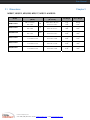
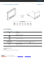
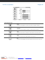
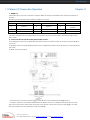
USER
MANUAL
Widescreen LCD Quad Display
Wide 19”, 22” Screen Size
Widescreen LCD Quad Display
Models
NQW922
NQW819
Widescreen LCD Drawer
Models
NQW119
4:3 LCD Quad Display
17", 19", 20" screen size
4:3 LCD QuaD Display
Models
NPQ817 / NPQ919 / NPQ1020
4:3 LCD Display
Models
NPQ117 / NPQ119 / NPQ120
Options: - DC Power
User Manual
Contents
Chapter 1
Getting Started
1.1
Important Safeguards..........................................................1
1.2
Regulatory Notice................................................................2
1.3
Before Installation................................................................3
1.4
Unpacking............................................................................3
1.5
Optional Accessories...........................................................3
1.6
Peripheral Products.............................................................4
Part 1
Widescreen LCD Quad Display
Chapter 2
NQW922 & NQW819
Chapter 3
2.1
Package Contents...............................................................5
2.2
Structure Diagram...............................................................6
2.3
I n s t a l l a t i o n .... ... ... ... ... .... ... ... ... ... .... ... ... ... ... .... ... ... ... ... .... ... . 7 - 8
2.4
Connection...................................................................9
NQW119
3.1
Package Contents...............................................................10
3.2
Structure Diagram...............................................................11
3.3
How to Install “One Man” Installation Slides................12-13
3.4
How t o Use the Slides......................................................14
3.5
Connection...................................................................15
Chapter 4
LCD Specification...............................................................................................16
Chapter 5
Dimensions……….................................................................................................17
Part 2
4:3 LCD Quad Display
Chapter 6
NPQ817, NPQ919 & NPQ1020
6.1
Package Contents.............................................................18
6.2
Structure Diagram.............................................................19
6.3
Installation.................................................................20
6.4
C o n n e c t io n . . . . . . . . . . . . . . . . . . . . . . . . . . . . . . . . . . . . . . . . . . . . . . . . . . . . . . . . . . . . . . . . . . . . 2 1
i-Tech Company LLC
TOLL FREE: (888) 483-2418 • EMAIL: [email protected] • WEB: www.iTechLCD.com
User Manual
Contents
Chapter 7
NPQ117, NPQ119 & NPQ120
7.1
Package Contents.............................................................22
7.2
Structure Diagram.............................................................23
7.3
How to Install “One Man” Installation Slides................24-25
7.4
How to Use the Slides......................................................26
7.5
Connect ion...... ... .... . ..... ... .... .... ..... ... .... .... ..... ... .... .... ..... ...2 7
Chapter 8
LCD Specification...............................................................................................28
Chapter 9
Dimensions……….................................................................................................29
Chapter 10
Operation
Chapter 11
10.1
On-screen Display Operation............................................30
10.2
On-screen Menu................................................................31
Quad Specification
11.1
11.2
11.3
11.4
11.5
11.6
11.7
Chapter 12
Options
12.1
Chapter 11
Basic System Connection..................................................32
Alarm I/O Connection & Operation..............................33-34
Remote Control Connection & Operation.....................35-39
Quad Display Connection............................................40
Quad Display On-screen Menu .................................. 41-43
VC R O p e r a t i o n s . . . . . . . . . . . . . . . . . . . . . . . . . . . . . . . . . . . . . . . . . . . . . . . . . . . . . . . . . . . . . 4 4
Quad Display Specification ...............................................44
DC Power..........................................................................45
Trouble Shooting.................................................................................................46
i-Tech Company LLC
TOLL FREE: (888) 483-2418 • EMAIL: [email protected] • WEB: www.iTechLCD.com
User Manual
1.1 Important Safeguards
Chapter 1
Please read all of these instructions carefully before you use the device. Save this manual for future reference.
What the warranty does not cover
■ Any product, on which the serial number has been defaced, modified or removed.
■ Damage, deterioration or malfunction resulting from:
□ Accident, misuse, neglect, fire, water, lightning, or other acts of nature, unauthorized product modification, or
failure to follow instructions supplied with the product.
□ Repair or attempted repair by anyone not authorized by us.
□ Any damage of the product due to shipment.
□ Removal or installation of the product.
□ Causes external to the product, such as electric power fluctuation or failure.
□ Use of supplies or parts not meeting our specifications.
□ Normal wear and tear.
□ Any other causes which does not relate to a product defect.
■ Removal, installation, and set-up service charges.
i-Tech Company LLC
TOLL FREE: (888) 483-2418 • EMAIL: [email protected] • WEB: www.iTechLCD.com
User Manual
1.2 Regulatory Notice
Chapter 1
Legal Information
First English printing, October 2002
Information in this document has been carefully checked for accuracy; however, no guarantee is given to the
correctness of the contents. The information in this document is subject to change without notice. We are not liable for
any injury or loss that results from the use of this equipment.
Safety Instructions
■ Unplug equipment before cleaning. Don’t use liquid or spray detergent; use a moist cloth.
■ Keep equipment away from excessive humidity and heat. Preferably, keep it in an air-conditioned environment with temperatures not exceeding 40º Celsius (104º Fahrenheit).
■ When installing, place the equipment on a sturdy, level surface to prevent it from accidentally falling and
causing damage to other equipment or injury to persons nearby.
■ When the drawer is in an open position, do not cover, block or in any way obstruct the gap between it and
the power supply. Proper air convection is necessary to keep it from overheating.
■ Arrange the equipment’s power cord in such a way that others won’t trip or fall over it.
■ If you are using a power cord that didn’t ship with the equipment, ensure that it is rated for the voltage
and current labeled on the equipment’s electrical ratings label. The voltage rating on the cord should be
higher than the one listed on the equipment’s ratings label.
■ Observe all precautions and warnings attached to the equipment.
■ If you don’t intend on using the equipment for a long time, disconnect it from the power outlet to prevent
being damaged by transient over-voltage.
■ Keep all liquids away from the equipment to minimize the risk of accidental spillage. Liquid spilled on to
the power supply or on other hardware may cause damage, fire or electrical shock.
■ Only qualified service personnel should open the chassis. Opening it yourself could damage the equipment and invalidate its warranty.
■ If any part of the equipment becomes damaged or stops functioning, have it checked by qualified service
personnel.
Regulatory Notices Federal Communications Commission (FCC)
This equipment has been tested and found to comply with the limits for a Class B digital device, pursuant to Part 15 of
the FCC rules. These limits are designed to provide reasonable protection against harmful interference in a residential
installation.
Any changes or modifications made to this equipment may void the user’s authority to operate this equipment. This
equipment generates, uses, and can radiate radio frequency energy and, if not installed and used in accordance
with the instructions, may cause harmful interference to radio communications.
However, there is no guarantee that interference will not occur in a particular installation. If this equipment does cause
harmful interference to radio or television reception, which can be determined by turning the equipment off and on,
the user is encouraged to try to correct the interference by one or more of the following measures:
■ Re-position or relocate the receiving antenna.
■ Increase the separation between the equipment and receiver.
■ Connect the equipment into an outlet on a circuit different from that to which the receiver is connected.
i-Tech Company LLC
TOLL FREE: (888) 483-2418 • EMAIL: [email protected] • WEB: www.iTechLCD.com
User Manual
1.3 Before Installation
Chapter 1
■ It is very important to locate the Rackmount LCD Drawer / Display in a suitable environment.
■ The surface for placing and fixing the Rackmount LCD Drawer / Display should be stable and level or mounted
into a suitable cabinet.
■ Make sure the place has good ventilation, is out of direct sunlight, away from sources of excessive dust, dirt,
heat, water, moisture and vibration.
■ Convenience for connecting the Rackmount LCD Drawer / Display to the related facilities should be well
considered too.
1.4 Unpacking
The LCD keyboard drawer comes with the standard parts shown on the package contents. Check and make sure
they are included and in good condition. If anything is missing, or damage, contact the supplier immediately.
1.5 Optional Accessories
1. Power Cord
1.1 IEC power cord
1.2 NEMA 5-15 power cord (US)
1.3 BS 1363 power cord (UK)
1.4 CEE 7/4 power cord (German)
1.5 AS 3112 power cord (Australia)
i-Tech Company LLC
TOLL FREE: (888) 483-2418 • EMAIL: [email protected] • WEB: www.iTechLCD.com
User Manual
1.6 Peripheral Products
Chapter 1
Item
Model No.
Description
Matrix Cat6 KVM
MC0116 / MC0216 / MC0316
MC1116 / MC1216 / MC2116
MC0132 / MC0232 / MC0332
MC1132 / MC1232 / MC2132
Matrix Cat6 16 port KVM
Matrix IP Cat6 16 port KVM
Matrix Cat6 32 port KVM
Matrix IP Cat6 32 port KVM
Matrix DB-15 KVM
M018/ M028 / M038
M118 / M128 / M218
M0116 / M0216 / M0316
M1116 / M1216/ M2116
Matrix DB-15 8 port KVM
Matrix IP DB-15 8 port KVM
Matrix DB-15 16 port KVM
Matrix IP DB-15 16 port KVM
Combo Cat6 KVM
NVC800 / NVCCE800 / NVCIP800
NVC1600 / NVCCE1600 / NVCIP1600
NVC3200/ NVCCE3200 / NVCIP3200
Combo Cat6 8 port KVM
Combo Cat6 16 port KVM
Combo Cat6 32 port KVM
Combo DB-15 KVM
NVS801 / NVCE800 / NVIP-802
NVS1601 / NVCE1600 / NVIP-1602
Combo DB-15 8 port KVM
Combo DB-15 16 port KVM
PS/2 DB-15 KVM
NV401A / NV801A / NV1601A
4 / 8 / 16 port PS/2 DB-15 KVM
Keyboard Drawer
NK1
NK2
Rackmount keyboard drawer (with
KVM options)
Rackmount keyboard drawer (short
depth version)
i-Tech Company LLC
TOLL FREE: (888) 483-2418 • EMAIL: [email protected] • WEB: www.iTechLCD.com
User Manual
2.1 Package Contents
NQW819 & NQW922
1 Rackmount LCD display x 1 pc
2 User manual x 1pc
3 6’ VGA cable (male to male) x 1pc
4 Power cord x 1pc
5 Auto switch power adapter x 1pc
6 M3.2*4.5mm screw x 4 pcs
7 Power adapter bracket x 1 pc
i-Tech Company LLC
TOLL FREE: (888) 483-2418 • EMAIL: [email protected] • WEB: www.iTechLCD.com
Chapter 2
User Manual
2.2 Structure Diagram
Chapter 2
RP-W719 & RP-W822
1 LCD interchangeable module kit
2 LCD membrane
3 Power adapter bracket
Power adapter bracket installation
M3.2*4.5mm screw x 4 pcs
i-Tech Company LLC
TOLL FREE: (888) 483-2418 • EMAIL: [email protected] • WEB: www.iTechLCD.com
User Manual
2.3 Installation
Chapter 2
NQW819
■ Install each screws shown in Figure 1.
Figure 1.
■ Fixed the LCD into the rack.
* M6 screws are not provided.
Figure 2.
i-Tech Company LLC
TOLL FREE: (888) 483-2418 • EMAIL: [email protected] • WEB: www.iTechLCD.com
User Manual
2.3 Installation
Chapter 2
NQW922
Figure 3.
Figure 4.
■ Install each screw shown in Figure 3.
* M6 screws are not provided.
■ Insert the upper part of the LCD display to the rack
shown in Figure 4.
Figure 5.
■ Push the lower part of the LCD into the rack.
Figure 6.
■ Installation completed.
i-Tech Company LLC
TOLL FREE: (888) 483-2418 • EMAIL: [email protected] • WEB: www.iTechLCD.com
User Manual
2.4 Connection
Chapter 2
NQW819 & NQW922
■ Please refer to P.27 - 39
Caution: The Rackmount LCD Drawer & Display are hot-pluggable, but components of connected
devices, such as the servers and KVM switch, may not be hot-pluggable. Plugging and unplugging
cables while servers and KVM are powered on may cause irreversible damage to the servers, KVM and
Rackmount LCD Drawer. Before attempting to connect anything to the Rackmount LCD Drawer, we
suggest turning off the power to all devices before connecting them. Apply power to connected devices
again only after the Rackmount LCD Drawer is receiving power. The company is not responsible for
damage caused in this way.
i-Tech Company LLC
TOLL FREE: (888) 483-2418 • EMAIL: [email protected] • WEB: www.iTechLCD.com
User Manual
3.1 Package Contents
NQW119
1 LCD drawer x 1 pc
2 6’ VGA cable (male to male) x 1pc
3 User manual x 1 pc
4 Power cord x 1 pc
5 Mounting bracket x 2 pcs
6 M6*15mm screw x 8 pcs
7 M6 cage nut x 8 pcs
8 Cup washer x 8 pcs
i-Tech Company LLC
TOLL FREE: (888) 483-2418 • EMAIL: [email protected] • WEB: www.iTechLCD.com
Chapter 3
User Manual
3.2 Structure Diagram
Chapter 3
NQW119
1 LCD interchangeable module kit
3 LCD + Quad display membrane
2 “One Man” Installation Slides
4 Thumb Screw
i-Tech Company LLC
TOLL FREE: (888) 483-2418 • EMAIL: [email protected] • WEB: www.iTechLCD.com
User Manual
3.3 How to Install “One Man” Installation Slides
Chapter 3
Install into rack
■ Attach the left and right mounting bracket to
rack 19” mounting rails.
■ Adjust the rear mouting bracket to fit your rack.
■ M6 screw and cup washer x 6 pcs included.
Caution: Leaving the screws slightly loose,
until you complete the installation in step
■ Pick up the LCD keyboard drawer.
■ Insert the LCD keyboard drawer into the
mounting bracket.
■ Pull and hold the left & right black arrow buttons
on the rails.
■ Return the LCD keyboard drawer to park position.
i-Tech Company LLC
TOLL FREE: (888) 483-2418 • EMAIL: [email protected] • WEB: www.iTechLCD.com
User Manual
3.3 How to Install "One Man" Installation Slides
Chapter 3
■ Attach front left and right mounting ears of the LCD
keyboard drawer to vertical mounting rails.
■ M6 screw and cup washer x 2 pcs included.
Complete the installation
■ Tighten all 8 pcs of M6 screw to complete the installation.
i-Tech Company LLC
TOLL FREE: (888) 483-2418 • EMAIL: [email protected] • WEB: www.iTechLCD.com
User Manual
3.4 How to Use the Slides
Chapter 3
NQW119
■ A black arrow release button is located on the
outside of each slide. (shown in Figure 7).
Figure 7
■ Pull and hold the black arrow button on either side
of the LCD keyboard drawer to unlock. (shown in
Figure 10).
Figure 8
■ Push the LCD keyboard drawer into the rack.
(shown in Figure 9).
Caution : Keep your fingers away from the slide top
Figure 9
i-Tech Company LLC
TOLL FREE: (888) 483-2418 • EMAIL: [email protected] • WEB: www.iTechLCD.com
User Manual
3.4 Connection
Chapter 3
NQW119
■ Please refer to P.28 - 40
Caution: The Rackmount LCD Drawer & Display are hot-pluggable, but components of connected
devices, such as the servers and KVM switch, may not be hot-pluggable. Plugging and unplugging
cables while servers and KVM are powered on may cause irreversible damage to the servers, KVM and
Rackmount LCD Drawer. Before attempting to connect anything to the Rackmount LCD Drawer, we
suggest turning off the power to all devices before connecting them. Apply power to connected devices
again only after the Rackmount LCD Drawer is receiving power. The company is not responsible for
damage caused in this way.
i-Tech Company LLC
TOLL FREE: (888) 483-2418 • EMAIL: [email protected] • WEB: www.iTechLCD.com
User Manual
4.1 Specifications
Chapter 4
NQW922, NQW819 & NQW119
Item
Diagonal Size
Description
19" TFT
22" TFT
1440 x 990
1680 x 1050
300
300
Color Support
16.7 M
16.7 M
Contrast Ratio (typ.)
1000:1
1000:1
Viewing Angle (H/V)
160˚ x 160˚
170˚ x 160˚
408 x 255
474 x 296
Tr Response Time (ms)
1.3
3.6
LCD Panel MTBF (hrs)
50,000
50,000
Max. Resolution
Brightness (cd/m²)
Display Area (mm)
VGA Signal Input
Analog RGB, 0.7Vp-p
Sync. Type
Separate H/V, Composite, SOG
720 x 400, 70 Hz
640 x 480, 60 / 70 / 72 / 75 Hz
800 x 600, 60 / 70 / 72 / 75 Hz
1024 x 768, 60 / 70 / 75 Hz
Resolution
1152 x 864, 60 / 70 / 75 Hz
1280 x 720, 60 / 70 / 75 Hz
1280 x 720, 60 / 75 Hz
1280 x 1024, 60 / 70 / 75 Hz
1280 x 1024, 60 / 75 Hz
1440 x 900, 60 Hz
Plug & Play DDC
Power Input
1680 x 1050, 60 Hz
EDID 1.3
Auto-sensing 100 to 240VAC, 50 / 60Hz
Power Consumption
Compatibility
Max. 48 Watt, Standby 5 Watt
Multi-platform - Mix PCs, SUNs, IBMs, HPs & DELLs.
Options
DC Power
DC power input with 12V, 24V, 48V selection
Environmental
Operation
0˚ to 50˚C Degree
Storage
-5˚ to 60˚C Degree
Relative Humidity
5~90%, non-condensing
Shock
10G acceleration (11ms duration)
Vibration
5~500Hz 1G RMS random vibration
i-Tech Company LLC
TOLL FREE: (888) 483-2418 • EMAIL: [email protected] • WEB: www.iTechLCD.com
User Manual
5.1 Dimensions
Chapter 5
NQW922, NQW819 & NQW119
Model
NQW922
NQW819
NQW119
Product Dimension
(W x D)
500.4 x 70.5mm
19.7 x 2.8”
480 x 71.5mm
x 2.8”
18.9
445 x 650 x 44 mm
17.5 x 25.6 x 1.73 ”
Packing Dimension
(W x D x H)
Net Weight
Gross Weight
9U
565 x 539 x 156 mm
22.2 x 21.2 x 6.1"
12 kg
26 lb
15 kg
33 lb
8U
565 x 495 x 156 mm
22.2 x 19.5 x 6.1"
8 kg
18 lb
10 kg
22 lb
581 x 755 x 172 mm 22.9
x 29.7 x 6.8”
13 kg
29 lb
18 kg
40 lb
i-Tech Company LLC
TOLL FREE: (888) 483-2418 • EMAIL: [email protected] • WEB: www.iTechLCD.com
User Manual
6.1 Package Contents
NPQ817, NPQ919 & RP-W1020QD
1 Rackmount LCD display x 1 pc
2 User manual x 1 pc
3 6’ VGA cable (male to male) x 1pc
4 Power cord x 1pc
5 Auto switch power adapter x 1pc
6 M3.2*4.5mm screw x 4 pcs
7 Power adapter bracket x 1 pc
i-Tech Company LLC
TOLL FREE: (888) 483-2418 • EMAIL: [email protected] • WEB: www.iTechLCD.com
Chapter 6
User Manual
6.2 Structure Diagram
Chapter 6
NPQ817, NPQ919 & NPQ1020
1 LCD interchangeable module kit
2 2-in-1 LCD + Quad display membrane
3 Power adapter bracket
Power adapter bracket installation
M3.2*4.5mm screw x 4 pcs
i-Tech Company LLC
TOLL FREE: (888) 483-2418 • EMAIL: [email protected] • WEB: www.iTechLCD.com
User Manual
6.3 Installation
Chapter 6
NPQ817, NPQ919 & NPQ1020
■ Install each screws shown in Figure 10.
Figure 10.
■ Fixed the LCD into the rack.
* M6 screws are not provided.
Figure 11.
i-Tech Company LLC
TOLL FREE: (888) 483-2418 • EMAIL: [email protected] • WEB: www.iTechLCD.com
User Manual
6.3 Installation
Chapter 6
NP920 & SNP920
■ Install each screws shown in Figure 12.
Figure 12.
■ Fixed the LCD into the rack.
* M6 screws are not provided.
Figure 13.
i-Tech Company LLC
TOLL FREE: (888) 483-2418 • EMAIL: [email protected] • WEB: www.iTechLCD.com
User Manual
6.4 Connection
Chapter 6
NPQ817, NPQ919 & NPQ1020
■ Please refer to P.28 - 40
Caution: The Rackmount LCD Drawer & Display are hot-pluggable, but components of connected
devices, such as the servers and KVM switch, may not be hot-pluggable. Plugging and unplugging
cables while servers and KVM are powered on may cause irreversible damage to the servers, KVM and
Rackmount LCD Drawer. Before attempting to connect anything to the Rackmount LCD Drawer, we
suggest turning off the power to all devices before connecting them. Apply power to connected devices
again only after the Rackmount LCD Drawer is receiving power. The company is not responsible for
damage caused in this way.
i-Tech Company LLC
TOLL FREE: (888) 483-2418 • EMAIL: [email protected] • WEB: www.iTechLCD.com
User Manual
7.1 Package Contents
NPQ117, NPQ119 & NPQ120
1 LCD drawer x 1 pc
2 6’ VGA cable (male to male) x 1pc
3 User manual x 1 pc
4 Auto switch power adapter ( for external power version) x 1pc
5 Power cord x 1pc
6 Mounting bracket x 2 pcs
7 M6*15mm screw x 8 pcs
8 M6 cage nut x 8 pcs
9 Cup washer x 8 pcs
i-Tech Company LLC
TOLL FREE: (888) 483-2418 • EMAIL: [email protected] • WEB: www.iTechLCD.com
Chapter 7
User Manual
7.2 Structure Diagram
Chapter 7
NPQ117, NPQ119 & NPQ120
1 LCD interchangeable module kit
3 LCD + Quad display membrane
2 “One Man” Installation Slides
4 Thumb Screw
i-Tech Company LLC
TOLL FREE: (888) 483-2418 • EMAIL: [email protected] • WEB: www.iTechLCD.com
User Manual
7.3 How to Install "One Man" Installation Slides
Chapter 7
Install into rack
■ Attach the left and right mounting bracket to
rack 19” mounting rails.
■ Adjust the rear mouting bracket to fit your rack.
■ M6 screw and cup washer x 6 pcs included.
Caution: Leaving the screws slightly loose,
until you complete the installation in step
■ Pick up the LCD keyboard drawer.
■ Insert the LCD keyboard drawer into the
mounting bracket.
■ Pull and hold the left & right black arrow buttons
on the rails.
■ Return the LCD keyboard drawer to park position.
i-Tech Company LLC
TOLL FREE: (888) 483-2418 • EMAIL: [email protected] • WEB: www.iTechLCD.com
User Manual
7.3 How to Install "One Man" Installation Slides
Chapter 7
■ Attach front left and right mounting ears of the LCD
keyboard drawer to vertical mounting rails.
■ M6 screw and cup washer x 2 pcs included.
Complete the installation
■ Tighten all 8 pcs of M6 screw to complete the installation.
i-Tech Company LLC
TOLL FREE: (888) 483-2418 • EMAIL: [email protected] • WEB: www.iTechLCD.com
User Manual
7.4 How to Use the Slides
Chapter 7
NPQ117, NPQ119 & NPQ120
■ A black arrow release button is located on the
outside of each slide. (shown in Figure 12).
Figure 12
■ Pull and hold the black arrow button on either side
of the LCD keyboard drawer to unlock. (shown in
Figure 13).
Figure 13
■ Push the LCD keyboard drawer into the rack.
(shown in Figure 14).
Caution : Keep your fingers away from the slide top
Figure 14
i-Tech Company LLC
TOLL FREE: (888) 483-2418 • EMAIL: [email protected] • WEB: www.iTechLCD.com
User Manual
7.5 Connection
Chapter 7
NPQ117, NPQ119 & NPQ120
■ Please refer to P.28 - 40
Caution: The Rackmount LCD Drawer & Display are hot-pluggable, but components of connected
devices, such as the servers and KVM switch, may not be hot-pluggable. Plugging and unplugging
cables while servers and KVM are powered on may cause irreversible damage to the servers, KVM and
Rackmount LCD Drawer. Before attempting to connect anything to the Rackmount LCD Drawer, we
suggest turning off the power to all devices before connecting them. Apply power to connected devices
again only after the Rackmount LCD Drawer is receiving power. The company is not responsible for
damage caused in this way.
i-Tech Company LLC
TOLL FREE: (888) 483-2418 • EMAIL: [email protected] • WEB: www.iTechLCD.com
User Manual
8.1 Specifications
Chapter 8
NPQ817, NPQ919, NPQ1020, NPQ117, NPQ119 & NPQ120
Item
Description
LCD Manufacturer
Diagonal Size
Max. Resolution
Brightness (cd/m²)
Color Support
17" TFT
19" TFT
20" TFT
1280 x 1024
1280 x 1024
1600 x 1200
300
300
300
16.7 M
16.7 M
16.7 M
Contrast Ratio (typ.)
1000:1
1000:1
800:1
Viewing Angle (H/V)
160˚ x 160˚
160˚ x 160˚
160˚ x 160˚
408 x 306
Display Area (mm)
338 x 270
376 x 301
Tr Response Time (ms)
1.3
1.3
1
LCD Panel MTBF (hrs)
50,000
50,000
50,000
VGA Signal Input
Analog RGB, 0.7Vp-p
Sync. Type
Separate H/V, Composite, SOG
720 x 400, 70 Hz
640 x 480, 60 / 70 / 72 / 75 Hz
640 x 480, 60 / 70 / 72 / 75 Hz
800 x 600, 60 / 70 / 72 / 75 Hz
1024 x 768, 60 / 70 / 75 Hz
Resolution
1152 x 864, 60 / 70 / 75 Hz
1280 x 720, 60 / 70 / 75 Hz
1280 x 720, 60 / 75 Hz
1280 x 1024, 60 / 70 / 72 / 75 Hz
1280 x 1024, 60 / 70 / 75 Hz
-
1400 x 1050, 60 Hz
Plug & Play DDC
Power Input
1600 x 1200, 60 Hz
EDID 1.3
Auto-sensing 100 to 240VAC, 50 / 60Hz
Power Consumption
Compatibility
Regulation Approval
Max. 48 Watt, Standby 5 Watt
Multi-platform - Mix PCs, SUNs, IBMs, HPs & DELLs.
FCC, CE
Options
DC Power
DC power input with 12V, 24V, 48V selection
Environmental
Operation
0˚ to 50˚C Degree
Storage
-5˚ to 60˚C Degree
Relative Humidity
5~90%, non-condensing
Shock
10G acceleration (11ms duration)
Vibration
5~500Hz 1G RMS random vibration
i-Tech Company LLC
TOLL FREE: (888) 483-2418 • EMAIL: [email protected] • WEB: www.iTechLCD.com
User Manual
9.1 Dimensions
Chapter 9
NPQ817, NPQ919, NPQ1020, NPQ117, NPQ119 & NPQ120
Model
Product Dimension
(W x D)
Packing Dimension
(W x D x H)
Net Weight
Gross Weight
NPQ817 series
480 x 71.5 mm
18.9 x 2.8"
8U
565 x 450 x 156 mm
22.2 x 17.7 x 6.1"
7 kg
15 lb
8.5 kg
19 lb
NPQ919 series
480 x 71.5 mm
18.9 x 2.8"
9U
565 x 495 x 156 mm
22.2 x 19.5 x 6.1”
8 kg
18 lb
10 kg
22 lb
NPQ1020 series
480 x 71.5 mm
18.9 x 2.8"
10U
565 x 539 x 156 mm
22.2 x 21.2 x 6.1"
12 kg
26 lb
15 kg
33 lb
NPQ117 series
442 x 600 x 44 mm
17.4 x 23.6 x 1.73"
581 x 755 x 172 mm
22.9 x 29.7 x 6.8"
12 kg
26 lb
17 kg
37 lb
NPQ119 series
442 x 600 x 44 mm
17.4 x 23.6 x 1.73"
581 x 755 x 172 mm
22.9 x 29.7 x 6.8”
13 kg
29 lb
18 kg
40 lb
NPQ120 series
442 x 650 x 44 mm
17.4 x 25.6 x 1.73"
589 x 856 x 168 mm
23.2 x 33.7 x 6.8"
14 kg
31 lb
19 kg
42 lb
i-Tech Company LLC
TOLL FREE: (888) 483-2418 • EMAIL: [email protected] • WEB: www.iTechLCD.com
User Manual
10.1 On Screen Display Operation
Chapter 10
LCD + Quad
display
membrane
For LCD OSD Menu
Membrane Switch
Function
Power light
Green = On
Orange = Power saving
Power on / off LCD
Display the OSD menu
Scrolls through menu options and adjusts the displayed control
(To auto adjustment by pressing the button
for 5 seconds)
Exit the OSD screen
Toggle analog, digital & video connection (DVI-D and video options only)
For Quad Display Control
Remarks:
■ Quad Display Control please refer to P.28 - 40
i-Tech Company LLC
TOLL FREE: (888) 483-2418 • EMAIL: [email protected] • WEB: www.iTechLCD.com
10.2 On-screen Menu
Chapter 10
OSD Configuration Page
Image:
To enter into the brightness, contrast, colour temp, red, green, and blue
Geometry:
To enter into the auto adjust, H position, V position, phase and clock
Video:
To enter into the colour, tint, sharpness, noise reduction, DCDi and TV Setup
Audio:
To enter into volume, bass, treble, balance, AVL and mute
Misc:
To enter into the language, OSD position, graphic mode, OSD time, ratio, reset
i-Tech Company LLC
TOLL FREE: (888) 483-2418 • EMAIL: [email protected] • WEB: www.iTechLCD.com
User Manual
11.1 Basic System Connection
Chapter 11
1. VCR in :
This BNC connector is connected to video output from VCR/DVR. A pre-recorded quad screen signal from a
tape can be played back through a VCR/DVR and displayed on the video output channels. Push the VCR
button (#2) to switch the device to VCR Playback mode.
2. VCR out :
This BNC connector is to be connected to the Video in from your VCR/DVR. It will only provide a quad screen
video to ensure an un-interrupted video recording for all four cameras. The display video is not affected by
the control panel.
3. Terminations :
These impedance switches are used to provide proper termination for each camera input. These switches
toggle between 75Ω and Hi-Z impedance. Incorrect termination will degrade the quality of the video signal.
All video inputs not “looped through” to another device, the corresponding switches need to be set to 75Ω
termination position. If another device is connected to video out loop through connector set the
corresponding termination switch to Hi-Z position. Any device connected to the video out loop through
connectors needs to be configure to 75Ω video termination. The factory default termination setting is 75Ω.
4. Ch1 In, Ch2 In, Ch3 In, and Ch4 In Video IN connectors :
These BNC connectors are used to connect to the video out from camera. Four cameras can be connected
to these connectors to form a quad screen in the following mapping order.
5. Ch1 Out, Ch2 Out, Ch3 Out, and Ch4 Out Video Loop through connectors :
These connectors are used to loop video signals from each camera out to other devices.
i-Tech Company LLC
TOLL FREE: (888) 483-2418 • EMAIL: [email protected] • WEB: www.iTechLCD.com
User Manual
11.2 Alarm I/O Connection Operation
Chapter 11
1. ALARM I/O :
This female type 9 pin D-sub connector is used for alarm sensor input and alarm output control connections. It
provides
Normal Open and Normal Close contacts for alarm out control.
Pin Assignment for Alarm Connector (female type)
PIN#
PIN#
PIN#
7
Normal Open
Contact
1
Sensor 1
4
Sensor 4
2
Sensor 2
5
Reset In
8
Common Contact
3
Sensor 3
6
GND
9
Normal Close Contact
The Alarm Hold Time can be configured from 0 second to 99 minutes for FIO-8037 / FIO-8134 through system
Setup menu.
2. VCR Connection for Tape Recording Start and Stop Control :
Connecting the contacts of VCR RECORD and STOP switch to the alarm output NC and NO contacts will allow
you to use
an ordinary VCR to record for longer period of time. Combined with alarm sensor detection, the VCR will record
only when
an alarm sensor is activated.
*. If more than one sensor have been trigged, VCR will start to record after the last trigged event.
*. In order to make use of the alarm called full screen display function, the VIDEO IN connector from the VCR
has to be connected to LIVE monitor connector of the device. If more than one sensor are trigged, VCR will
then record all the events in full screen mode accordingly.
i-Tech Company LLC
TOLL FREE: (888) 483-2418 • EMAIL: [email protected] • WEB: www.iTechLCD.com
User Manual
11.2 ALARM I/O Connection & Operation
Chapter 11
3 Sensor Activated Alarm
The unit is equipped with 4 alarm sensor inputs. If any alarm is activated:
■ the built-in buzzer will be activated.
■ the quad will switch the corresponding channel indicator LED to blinking mode.
■ a warning message depending on different models will be displayed as follows:
Quad output channel (#4)
Blinking Alarm & Title message on the activated
channel in quad screen
LIVE output channel (#5)
Full screen display of the activated channel. Also
display a blinking Alarm message
Above mentioned alarm can be cleared by: If the device is operated under Security Lock ON mode, Push Lock
button for 2 seconds to disable the function then push any button in the front panel.
4 Video Loss Alarm
Loss of video at any input is automatically detected by the device. The device will:
■ Activate the built-in buzzer.
■ Switch the corresponding channel indicator LED to blinking mode.
■ Display warning message on quad screen:
Quad output channel (#4)
■ The warning message and the buzzer can be
cleared by pushing Lock button (#2) for more than 4
seconds if the device is operated under Security lock
On mode, or pushing any button on the front panel if
the device is operated under Security lock OFF mode.
Blinking Video Loss & Title message
on the activated channel in quad
screen
i-Tech Company LLC
TOLL FREE: (888) 483-2418 • EMAIL: [email protected] • WEB: www.iTechLCD.com
User Manual
11.3 Remote Control Connection
i-Tech Company LLC
TOLL FREE: (888) 483-2418 • EMAIL: [email protected] • WEB: www.iTechLCD.com
Chapter 11
User Manual
11.3 Remote Control Connection & Operation
Chapter 11
The device may be controlled via the male type 9 pin D-sub/RS-232 connector (#13) from a RC-5002 keypad, terminal
or computer using ASCII code.
Note: Please power off the unit before connecting the Remote Control keypad.
1. Pin assignment of the male type 9 pin D-sub connector:
Pin Assignment for Remote Control Connector
1
GND
4
NC
7
VCC
2
RX
5
NC
8
GND
3
TX
6
VCC
9
GND
When a computer is used to control this device through a RS-232 port, pin 6, 7, 8, and 9 must be disconnected to
prevent connecting the VCC and GND signals from the device to the computer. A RS-232 port only uses pin 1, 2, and 3
for control
signal transmission.
2. A terminal or computer can be connected to the male type 9 pin D-sub connector on the real panel from it RS-232
port to control this device using standard, uppercase ASCII codes.
2.1 The ASCII command codes for the quad are listed in the table below. The transmission protocol is 1200-baud
rate, 8 data bit, 1 start bit, 1 stop bit, and no parity.
Function
ASCII Command Code
Quad Screen Display
E
CH 1
A
CH 2
B
CH 3
C
CH 4
D
Freeze *1
EA, EB, EC, ED
Auto Switching Sequence
F
VCR/Live
G
Key Lock *2
H
Setup Menu *3
GH
Text Select Down *4
(GH) A
Text Select Up
(GH) B
Cursor Left
(GH) C
Cursor Right
(GH) D
Alarm Reset
I
i-Tech Company LLC
TOLL FREE: (888) 483-2418 • EMAIL: [email protected] • WEB: www.iTechLCD.com
User Manual
11.3 Remote Control Connection & Operation
Chapter 11
*1. For FIO-8037: in order to control the device to operate in Zoom mode, the computer has to
first send command code ” to switch the signal source from camera to VCR/DVR, at this time
the device will automatically zoom channel 1 video from VCR/DVR to full screen. User can
then input a corresponding channel code to zoom any other specific channel. Input the
corresponding channel code again to put the specific channel to freeze mode and send
the code again to clear the freeze mode.
Example: Input GE, (GE) B, (GE) C, and (GE) D for zooming the video signal in channel 1 to 4
from VCR/DVR. Input “A”, “B”, “C”, “D” again to freeze the specific channel. Send
command code “G” again to get back to Live input mode.
*2. Computer has to send out command code “H” continuously for 2 seconds to switch the
device between security lock ON and OFF mode. If any alarm is activated under security
lock ON mode, the device has to send out command code “H” continuously for more than
4 seconds to clear the alarm.
*3. Setup menu is switched ON by sending VCR/DVR and Lock button codes together.
*4. Text Select and Cursor Control functions can be performed only under menu Setup mode.
2.2 Right after computer/terminal has sent out the above mentioned control command code to the
device, the device will respond with following status code back to computer through RS-232 port:
Status
Code
Quad Status
Status
Code
Quad Status
EF
Device in Quad mode
DE
CH1 in Sequence mode
EE
CH1 in Freeze mode
DD
CH2 in Sequence mode
ED
CH2 in Freeze mode
DB
CH3 in Sequence mode
EC
CH1 & 2 in Freeze mode
D7
CH4 in Sequence mode
EB
CH3 in Freeze mode
CF
Quad display in Sequence mode
EA
CH1 & 3 in Freeze mode
E9
CH2 & 3 in Freeze mode
E
CH1 in Full screen mode
E8
CH1, 2, & 3 in Freeze mode
D
CH2 in Full screen mode
E7
CH4 in Freeze mode
B
CH3 in Full screen mode
E6
CH1 & 4 in Freeze mode
7
CH4 in Full screen mode
E5
CH2 & 4 in Freeze mode
E4
CH1, 2 & 4 in Freeze mode
Attach to above code
E3
CH3 & 4 in Freeze mode
XX-DF
Buzzer/VCR ON
E2
CH1, 3, & 4 in Freeze mode
XX-7F
Security lock ON
E1
CH2, 3, & 4 in Freeze mode
XX-3F
Buzzer & Security lock ON (Stop)
E0
CH1, 2,3, & 4 in Freeze mode
i-Tech Company LLC
TOLL FREE: (888) 483-2418 • EMAIL: [email protected] • WEB: www.iTechLCD.com
User Manual
11.3 Remote Control Connection & Operation
Chapter 11
2.3 The configuration of the status code for both normal and alarm operations:
There are total 2 bytes of the status codes. Byte one, the first 8 bits, shows the current status of the
operation modes that the unit is in. Byte two, the second 8 bits, shows the current status of the
alarm operations of the unit.
BYTE 1: Status code for normal operation modes
b7
b6
b5
b4
LOCK
VCR
SEQU
QUAD
b3
b2
b1
b0
CH4
CH3
CH2
CH1
Channel Select
1110 = CH1
1101 = CH2
1011 = CH3
0111 = CH4
Display Mode
0 = Quad screen display
1 = Full Screen display
Auto-sequencing mode
0 = Auto sequencing mode
1 = Quad or full screen mode
VCR mode
0 = VCR operation
1 = Live operation
Security Lock mode
0 = Security lock ON mode
1 = Security lock OFF mode
Menu Setup mode
00 = Menu setup mode
i-Tech Company LLC
TOLL FREE: (888) 483-2418 • EMAIL: [email protected] • WEB: www.iTechLCD.com
User Manual
11.3 Remote Control Connection & Operation
Chapter 11
BYTE 2: Status code for alarm operations: The first 4 bits show the sensor activated alarm status of each
channel; next 4 bits show the video loss alarm status of each channel. The digit “1” means alarm event is
detected, and “0” means no alarm event is detected.
b7 - b4: Sensor Activated Alarm
b3 - b0: Video Loss Alarm
b7
b6
b5
b4
b3
b2
b1
b0
CH4
CH3
CH2
CH1
CH4
CH3
CH2
CH1
Sensor activated Alarm
0001 = CH1 activated
0010 = CH2 activated
0100 = CH3 activated
1000 = CH4 activated
Video Loss Alarm
0001 = CH1 activated
0010 = CH2 activated
0100 = CH3 activated
1000 = CH4 activated
i-Tech Company LLC
TOLL FREE: (888) 483-2418 • EMAIL: [email protected] • WEB: www.iTechLCD.com
User Manual
11.4 Quad Display Operation
Chapter 11
1 Lock: Security locks out button. Push this button for 2 seconds to enable control panel lock out function. Push this button
again for 2 seconds to disable the function.
2 VCR: Push this button to enter into VCR Playback/Zoom operation. In this mode, the output video is displaying the video
signal from VCR. When operated in Full Screen display mode, push select buttons (#5) to zoom any specific camera
signal pre-recorded on the tape in quad format. Push the select button (#5) again to freeze the expanded picture on
the screen.
VCR
button (#2)
Quad
button (#4)
CH Select
button (#5)
Function
ON
ON
OFF
ON
OFF
Push Once
Display quad video signal from VCR tape
Call up specific quadrant from tape in full screen mode
ON
OFF
Push Twice
Freeze specific quadrant from tape in full screen mode
OFF
X
X
Exit VCR operation and back to normal operation mode
#1, #2 Setup buttons: Push these two buttons simultaneously to get into Menu Setup mode and display page 1 of system
setup menu. Push these two buttons simultaneously again to display page 2 of the setup menu. Use page 1 to program
time/date and camera title and page 2 to configure alarm operations. Under menu setup mode, Channel Select buttons
(#5) are used for cursor control and text selection to program the setup menu. Push the setup buttons simultaneously again
to save the setting. Push the setup buttons fourth time to get back to ordinary operation mode.
Function
UP, DOWN
< , >
Push once
Page 1 menu for time / date / title programming
Text Selection
Cursor Control
Push twice
Page 2 menu for alarm configuration
Text Selection
Cursor Control
Push the third time
Push the fourth time
3 Sequ.:
4
CH Select buttons (#5)
Setup buttons (#1, #2)
Save the settings
Yes / No
Exit setup mode, back to normal
Push this button to enable full page auto sequencing mode. Push this button again to disable it.
: Push this button to switch between Quad/ Full Screen display mode.
5
buttons: When operated in Quad mode, these buttons are used to freeze any specific camera by
pushing the corresponding button. When operated in Full Screen display mode, these buttons are used to select specific
camera to be displayed in full screen.
Quad button (#4)
Channel Select buttons (#5)
Function
ON
ON
Freeze specific camera video in Quad screen mode
OFF
ON
Call up specific camera video in full screen mode
These buttons are also used as cursor control and text select keys under Setup menu mode.
i-Tech Company LLC
TOLL FREE: (888) 483-2418 • EMAIL: [email protected] • WEB: www.iTechLCD.com
User Manual
11.5 Quad Display On-screen Menu
Chapter 11
Right after the unit is turned on, The monitor will display the last setting on the Setup Menu.
1. Page 1 of the Setup Menu - Display Setting
Push Setup buttons (#1, #2) simultaneously to display the Setup Menu on the screen. There are total two pages in the Setup
Menu. Page 1 is used to program TIME, DATE, and camera TITLE. Page 2 is used to program Alarm Operations. Under this
mode, channel selection buttons (#5) on the front panel are used for cursor control and text selection. Use the cursor
control buttons "<" and ">" to move the cursor to the location as desired to program, and use the text select buttons " "
and " " to choose the right alphanumeric character to program.
Page 1: Setting the TIME, DATE, TITLE, and DWELL time:
CH
TITLE
QUAD
1
CH 1
2
CH 2
3
CH 3
4
CH 4
LIVE VIDEO FREEZE
VIDEO OUT:
TITLE:
TIME: 23 : 10 : 10
DATE: 12 - 25 - 2003
DWELL
TIME
03S
03 S
03 S
03 S
03 S
ON
QUAD
ON
ON
ON
LIVE
ON
ON
ON
1.1 TITLE setup:
The Title menu permits the setup of separate titles for each video channel. 8 characters may be entered for each video
channel. The available alphanumeric characters are:
0, 1, 2, 3, 4, 5, 6, 7, 8, 9, A, B, C, D,..... X, Y, Z, . , :, - , / , < , >,
,
, space ,
1.2 DWELL Time setup:
The Dwell time menu permits setting the dwell time for all cameras and the Quad Screen on the LIVE output channel. The
menu shows a table of all cameras and associated dwell time. Dwell time can be programmed by setting a number
between 00 to 99 for each channel in the menu.
■ 01 through 99: Adds the camera input to the auto switching SEQUENCE, with the corresponding dwell time in seconds.
■ 00: Skips the camera input in the auto switching SEQUENCE.
1.3 TIME/DATE setup:
Time and date information can be displayed on the video output channel through both LIVE and QUAD connector.
Bottom of page 1 is used to set the values of time and date and also to enable or disable the display at each output
channel.
The date and time will display in the “MM-DD-YYYY HH:MM:SS” format for NTSC model and “DD-MM-YYYY HH:MM:SS”
format for PAL model.
1.4 TITLE/TIME/DATE disable and enable on LIVE and QUAD video output channel:
The Title/Time/Date display on each output channel can be enabled or disabled by setting ON or OFF in the
corresponding entry.
i-Tech Company LLC
TOLL FREE: (888) 483-2418 • EMAIL: [email protected] • WEB: www.iTechLCD.com
User Manual
11.5 Quad Display On-screen Menu
Chapter 11
2 Page 2 of the setup menu- Alarm Setting
Push Setup buttons (#1, #2) simultaneously and push (#1) button again to display page 2 of the setup menu on the screen.
This Alarm Setting menu is used to set the desired alarm configuration like buzzer, V-loss alarm and V-loss relay.
ALARM SETTING
CH
SENSOR
1
OPEN
2
OPEN
3
OPEN
4
OPEN
SENSITIVITY:
DURATION:
BUZZER:
V-LOSS ALARM:
V-LOSS RELAY:
TYPE
NO
NO
NO
NO
STATUS
ON
ON
ON
ON
0.3 S
30 S
ON
ON
OFF
2.1 Sensitivity:
The features are not applicable in these model.
2.2 Alarm Hold Duration:
The features are not applicable in these model.
2.3 Buzzer:
The device has a build-in buzzer to signal a detected alarm through sound. User can choose to disable the buzzer by
setting it to OFF.
2.4 V-Loss Alarm:
This entry is used to enable or disable the video loss alarm. The device automatically detects loss of video at any input if this
entry is set to ON. User can choose to disable this feature by setting it to OFF for applications like video conferencing or
others that will need constant video source switching.
2.5 V-Loss Relay Control:
The device is equipped with an alarm controlled relay, which can be activated by both sensor trigged alarm and video
loss alarm. This entry allows user to disable the relay activation from a loss of video in any camera input.
3 Save the settings and exit Setup Menu mode
Push (#1) button again will allow you to save the settings and go back to the normal operation mode and show a quad
display on the screen.
i-Tech Company LLC
TOLL FREE: (888) 483-2418 • EMAIL: [email protected] • WEB: www.iTechLCD.com
User Manual
11.5 Quad Display On-screen Menu
Chapter 11
4: The setup menu can be reset to factory setting by pushing the Setup buttons (#1, #2) and power on the quad
simultaneously. The factory setting is as follows:
CH
TITLE
QUAD
1
CH 1
2
CH 2
3
CH 3
4
CH 4
LIVE VIDEO FREEZE
VIDEO OUT:
TITLE:
TIME: 23 : 10 : 10
DATE: 12 - 25 - 2003
DWELL
LIVE
ON
ON
ON
TIME
03S
03 S
03 S
03 S
03 S
ON
QUAD
ON
ON
ON
CH
SENSOR
1
OPEN
2
OPEN
3
OPEN
4
OPEN
SENSITIVITY:
DURATION:
BUZZER:
V-LOSS ALARM:
V-LOSS RELAY:
ALARM SETTING
TYPE
NO
NO
NO
NO
STATUS
ON
ON
ON
ON
0.3 S
30 S
ON
ON
OFF
5. The Quad Display Mode
5.1 Push Quad display button (#4) to switch between Quad screen and Full screen display mode. Right after you
turn on the system, the unit is in the quad mode and displays cameras 1-4.
5.2 Use page 1 of the Setup menu to turn the Title display ON/OFF on each channel and also enable and disable
the Time and Date display on LIVE and QUAD output channels.
5.3 Under Quad screen mode, push channel select button to freeze each camera input.
6. The Full Screen Display Mode
6.1 Push Quad button (#4) to OFF to enter Full screen display mode. Under this mode, you may call up any spe
cific channel in full screen by simply pushing the corresponding channel selection button.
6.2 Push the Quad button (#4) to ON to return to the quad mode.
7. The Still Frame Display Mode
7.1 If the still screen mode is desired, first turn the quad display button (#4) to ON to set the unit to display in the
quad mode. At this time you may press any of the four channel selection buttons (#5) to freeze the
corresponding channel.
7.2 Under Zoom On VCR playback mode, if the unit is showing quad screen, pushing the channel selection but
tons (#5) will call up the specific channel to display in full screen. Push the same channel selection button
again to freeze that channel in full screen.
8. The Auto-Sequence Mode
Push the Sequence button (#3) to ON to set the device to work as a sequencer. Under this mode, the display sequence first
starts with a quad screen and then continues to display each camera input in full screen, and then gets back to quad screen
and so on. Press the Sequence button (#3) to OFF to release this mode.
i-Tech Company LLC
TOLL FREE: (888) 483-2418 • EMAIL: [email protected] • WEB: www.iTechLCD.com
User Manual
11.6 VCR Operations
Chapter 11
Zoom on VCR playback operation:
Push VCR button (#2) to ON will switch the device to VCR playback mode. Under this mode, if the device is on quad
display mode, a pr-recorded quad display video in the tape will be shown on the screen. If the device is in Full screen
display mode, push any channel select buttons (#5) will select and expand the corresponding quadrants of the pre-
Chapter 11
11.6 Quad Display Specifications
Item
Model Number
Description
QD (NTSC)
QD (PAL)
Number of Color
16.7 M
16.7 M
Imaging System
NTSC
PAL
1024 x 525
1024 x 625
60
50
Resolution
Refresh Rate
Video
Input
Video
Output
Camera Input
1.0 Vpp, 75 Ohm x 4
VCR Input
1.0 Vpp, 75 Ohm x 1
Live Monitor
1.0 Vpp, 75 Ohm x 1
Loop Through Out
1.0 Vpp, 75 Ohm x 4
VCR Output
1.0 Vpp, 75 Ohm x 1
Auto Gain Control
Yes
Time / Date
Ye
On Screen Display
Yes
Camera Title
Display Format
Dwell Time
8 Character Title
2 x Zoom On
Playback
Yes
QUAD
Yes
FULL
Yes
SEQUENCY
Yes
0 to 99 Sec Adjustable
Built-in Buzzer
Yes
Key Lock
Yes
i-Tech Company LLC
TOLL FREE: (888) 483-2418 • EMAIL: [email protected] • WEB: www.iTechLCD.com
User Manual
Chapter 12
12.1 DC Power Options
NQW819 & NQW922
NPQ817, NPQ919 & NPQ1020
DC Power input
NQW119 & NPQ120
DC Power input
Model
12V
24V
48V
Input voltage:
12-Volt
24-Volt
48-Volt
Input range:
9 ~ 18V
18 ~ 36V
36 ~ 75V
- No load
50 mA
50 mA
50 mA
- Full load
4950 mA
2450 mA
1220 mA
Output voltage:
12-Volt
12-Volt
12-Volt
Output current:
4.16A
4.16A
4.16A
Efficiency
84%
85%
85%
Input rating
Input current
Output rating
Remarks:
■ Package does not include 1 x power cord and 1 x AC power adapter
i-Tech Company LLC
TOLL FREE: (888) 483-2418 • EMAIL: [email protected] • WEB: www.iTechLCD.com
User Manual
13.1 Troubleshooting
Chapter 13
1. How do I adjust the resolution?
To change monitor resolution, click Start -> Control Panel -> Display. Select Setting tab to adjust the monitor resolution in
Desktop Area. The available resolutions, "640 x 480", "800 x 600", "1024 x 768", "1152 x 864", "1280 x 1024", are determined by
the display card in your computer.
2. Is interference signal appeared on LCD normal when shutting down the computer?
In rare cases, interference may appear on the monitor. This may be caused by signal rate of VGA card and is considered
normal. The image quality can be improved by adjusting the phase or pixel rate automatically or manually.
3. The membrane power light is not ON
Press the power On / Off on LCD membrane to check if the monitor is in the ON mode.
Check the power cord is properly connected to the LCD keyboard drawer and power outlet.
4. Screen image is not centered or sized properly
Press the
button for two seconds to automatically adjust the image.
Adjust the H-position and V-position settings via On-screen menu.
The company reserves the right to modify product specifications without prior notice and assumes no responsibility for any error which may appear in this
publication.
All brand names, logo and registered trademarks are properties of their respective owners.
Copyright 2009 i-Tech Company LLC. All rights reserved.
i-Tech Company LLC
TOLL FREE: (888) 483-2418 • EMAIL: [email protected] • WEB: www.iTechLCD.com