1
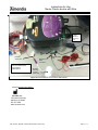
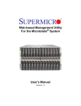
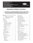
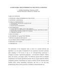
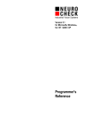
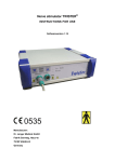
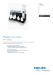
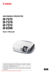
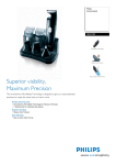
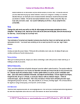
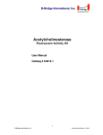
Instructions for Use Neuro Check® device with Wire DEVICE DESCRIPTION: The Neuro Check® device assists in the localization of nerve roots during spinal surgery where visualization is limited. The Neuro Check is designed to route electrical stimulus signals from a standard Electromyography (EMG) System to two sets of electrodes on the device in order to make an assessment as to relative nerve root location. It is comprised of a proximal handle, a rigid shaft, and a thin flexible distal platform featuring an array of electrodes on the top and bottom surfaces with embedded radiopaque markers (See Figure 1 below). Flexible Platform Cable Rigid Shaft Switch Figure 1: Neuro Check device Electrodes Tip Radiopaque Markers Figure 2: Flouroscopic Image of Flexible Electrode Platform HOW SUPPLIED: The iO-Flex® Neuro Check device is supplied sterile for single-patient use and is packaged with the iO-Flex® Wire to facilitate placement of the Neuro Check device and other iO-Flex®devices. Order Number Description iO-NCW iO-Flex Neuro-Check with Wire LBL1210 Rev. Q (DCR 15-0004, Effective Date: 2015-04-07) Page 1 - 17 Instructions for Use Neuro Check® device with Wire INTENDED/INDICATION FOR USE: The Neuro Check device can be used with an iO-Flex cutting and biting device for localization of motor nerves in settings where visualization is compromised. CONTRAINDICATIONS: None known. WARNINGS: Do not proceed with iO-Flex® decompression devices unless all steps are repeated and an acceptable EMG response indicating safe location is achieved. Patient movement may occur during stimulation and may lead to inadvertent neural injury. Take adequate steps to avoid stimulation when patient movement could cause injury. Portable and mobile RF communications equipment can affect function of the device. Do not use Neuro Check in conjunction with high frequency monopolar or bipolar electrosurgical equipment and neurodiagnostic equipment. Simultaneous use may result in burns at the site of the electrical stimulator and/or amplifier electrodes, and possible damage to the electrical stimulator. The system is not designed to operate in an explosive environment or in the presence of flammable anesthetics. The use of accessories, transducers and cables other than those specified by Amendia, may result in increased electro-magnetic emissions or decreased electro-magnetic immunity of the device. Do not attempt to service unit. No user serviceable parts are inside. Decompressing L1/L2 with the iO-Flex system is not advised due to the theoretical risk of damage to the conus medullaris and the low incidence of stenosis at this level. PRECAUTIONS: This device should only be used by personnel trained in the use of this device. Use only as directed and described in this IFU. Read all instructions prior to use including the Directions for Use for the NeuroCheck EMG Connection Set Up Failure to properly follow instructions may result in improper functioning of the device and may lead to patient injury. The Neuro Check device is intended to be used in conjunction with a certified, Nationally Recognized Testing Lab (NRTL) approved Electromyography (EMG) intra-operative neuromonitoring system, capable of outputting stimulus signals under the following conditions: Useable Ranges Recommended Stimulus Settings Neuro Check Stimulus Conditions Frequency Pulse Width 3.13 – 5.00 Hz max. 150 - 500µs max. 4.13 Hz LBL1210 Rev. Q (DCR 15-0004, Effective Date: 2015-04-07) 300µs Output Current 0.5 - 50mA max. 0.5 - 50mA max. Page 2 - 17 Instructions for Use Neuro Check® device with Wire The iO-Flex Wire is manufactured from a nickel-titanium alloy. Persons allergic to nickel-titanium alloy (including the major elements of nickel and titanium) may suffer an allergic reaction to this device. For use only with iO-Flex System devices. Do not use with other than specified components from another manufacturer. Do not use the product after the “Use By” date. Do not use the product if packaging integrity appears compromised, open, or damaged in any way! Do not attempt use if any component of the system appears damaged, bent, crushed, or is missing! For single patient use only. Do not reuse or resterilize! Reuse or attempted resterilization of the device may lead to device failure and subsequent patient injury. Attempted resterilization of the device may create the risk of contamination and patient infection! Do not use with neuromuscular blocking agents as these may impair EMG collection resulting in false readings! Do not use excessive force when pulling in or positioning as the device or neural structures may become damaged! Do not immerse the device in liquid. Immersing the device in liquid could cause the unit to fail! CAUTION: Always exercise caution handling the sharp distal tip of the iO-Wire to prevent needle-stick injuries! CAUTION: Federal (U.S.A.) law restricts this device to sale by or on the order of a physician. ADVERSE EVENTS The complication rate of the iO-Flex Neuro Check or any iO-Flex System Device in commercial use has been demonstrated to be low (<5% device-related). The events listed below are associated with use of the iOFlex System in order of more to least likely. Transient nerve irritation Hematoma Bone fracture Durotomy with or without CSF leakage Neuropathy Bleeding requiring transfusion Infection Paralysis Bowel/Bladder incontinence LBL1210 Rev. Q (DCR 15-0004, Effective Date: 2015-04-07) Page 3 - 17 Instructions for Use Neuro Check® device with Wire DIRECTIONS FOR USE: Step Action 1 Inspect all packages for damage. Open using sterile technique and inspect for any signs of physical damage to the device and cable. 2 Remove the Neuro Check device and Wire from the package. 3 4 5 6 7 8 IF... access is to be provided through a fixed tube, THEN... use a tube no more than 9cm in length with a minimum inner diameter (ID) of 16mm. After access to the posterior spinal canal has been achieved and the iO-Flex® Probe has been properly positioned (see Instructions for Use - iO-Flex Probe), introduce the sharp distal end of the Wire into the proximal handle of the Probe. Advance the Wire through the iO-Flex Probe and out the skin lateral to the initial incision. Adjust the Probe as necessary to achieve desired iO-Wire exit trajectory. While depressing the release button on the Distal Handle, advance the sharp end of the Wire through the funnel of the Distal Handle to desired location. The Distal Handle can be repositioned at any time by again depressing the release button and moving the handle relative to the Wire. (See Instructions for Use, Distal Handle). When the Wire is in the desired position, retract the Catheter of the Probe and remove the Probe (See Instructions for Use, iO-Flex Probe). Attach the Neuro Check device to the proximal end of the Wire. Hold the Wire at a 90 degree angle to the tip of the Neuro Check device. Insert the barrel feature of the Wire into the opening on the Neuro Check device and rotate it 90 degrees to lock it into place (See Figure 3). Neuro Check Tip iO-Wire Barrel Step 1. Align Wire barrel with Neuro Check device tip. Step 2. Insert Wire barrel into Neuro Check device tip. Step 3. Rotate Wire 90° up wards and pull forward. Figure 3: Engaging the iO-Wire to the Neuro Check Tip LBL1210 Rev. Q (DCR 15-0004, Effective Date: 2015-04-07) Page 4 - 17 Instructions for Use Neuro Check® device with Wire Step 9 Action Advance the Neuro Check device into the foramen ensuring that the white surface of the handle and more importantly, the corresponding electrodes of the Neuro Check device adjacent to the white handle, face away from the patient (see Figure 4). White Handle Surface Figure 4: Neuro Check device orientation during insertion 10 Use fluoroscopic guidance to confirm correct placement and to confirm that Electrode Platform is not twisted. (See Figure 5). CAUTION: Do not stimulate while advancing the Neuro Check device into position. Figure 5: Fluoroscopic image of twisted Neuro Check device. LBL1210 Rev. Q (DCR 15-0004, Effective Date: 2015-04-07) Page 5 - 17 Instructions for Use Neuro Check® device with Wire Step 11 Action Set the EMG system to output the following recommended stimulus settings: Useable Ranges Recommended Stimulus Settings Neuro Check Stimulus Conditions Frequency Pulse Width 3.13 – 5.00 Hz 150 - 500µs 4.13 Hz 300µs Output Current 0.5 - 50mA max. 0.5 - 50mA max. Warning: Set up EMG software to limit the maximum allowable stimulation current to 50mA during use of the Amendia Neuro Check Device to reduce the possibility of overstimulation. 12 Refer to the hospital supplied EMG intra-operative Neuromonitoring user manual for specific set-up and operation. 13 The NeuroCheck® device is able to stimulate with electrodes facing in the direction of either White or Black handle shell orientation (stimulation surface). The slider switch on the handle determines the stimulation surface. With the White field visible through the status window, stimulation occurs at the electrodes corresponding to the White surface of the device (see Figure 6). When the all Black field is visible, stimulation is active on the corresponding Black surface of the device (see Figure 8). When the circle is visible the device does not transmit current (OFF state) (see Figure 7) Figure 6: Stimulation active White surface Figure 7: OFF-state Figure 8: Stimulation active – Black surface Note: Status window exists on both White and Black surfaces of device. (White surface shown above). 14 After the Neuro Check device is positioned correctly, begin by stimulating the White surface of the Neuro Check device. Slide the switch until the White field is visible. Starting at 0 mA, gradually ramp up current until an EMG response is attained. LBL1210 Rev. Q (DCR 15-0004, Effective Date: 2015-04-07) Page 6 - 17 Instructions for Use Neuro Check® device with Wire Step 15 16 17 Action WARNING: Set up EMG System to limit the maximum allowable stimulation current to 50mA during use of the Amendia Neuro Check Device to reduce the possibility of overstimulation. Note the required threshold stimulation current to elicit the EMG response. Reduce current to 0 mA. Slide the switch until the Black field is visible. Again, slowly increase current up from 0 mA, just until an EMG response is elicited. WARNING: Set up EMG System to limit the maximum allowable stimulation current to 50mA during use of the Amendia Neuro Check Device to reduce the possibility of overstimulation. Note the required threshold stimulation current to elicit the EMG response. Reduce current to 0mA. Note: During threshold stimulation current determination process, the stimulation of each surface is stopped once an EMG response is elicited by that surface. The delivered current thresholds are dependent on the patient response. It can be expected that the White surface current thresholds will differ from the Black surface current thresholds. 18 19 When safe device-to-nerve-root location is achieved (device found to be dorsal to the nerve root), turn off stimulus signal, disengage and remove the Neuro Check, leaving the Wire in place. CAUTION: Do not proceed with iO-Flex decompression devices unless the nerve to wire relative location is visualized or all steps are repeated and an acceptable EMG response indicating safe device location is achieved. Disengage the Neuro Check device from the proximal end of the Wire as illustrated below: (See Figure 9). Step 1. Align Wire and Neuro Check device Rx tip straight and push wire into the Rx tip. Step 2. Rotate Wire 90° downwards. Step 3. Pull Wire away from Rx tip Figure 9: Disengaging the wire from the Neuro Check Tip. 20 The iO-Wire is now in the desired position and ready to accept an iO-Flex Microblade Shaver device. Refer to the iO-Flex MSB Instructions for Use to continue. LBL1210 Rev. Q (DCR 15-0004, Effective Date: 2015-04-07) Page 7 - 17 Instructions for Use Neuro Check® device with Wire Step 21 Action At the completion of the procedure, dispose of used product in accordance with all local regulations for disposable medical products. Technical Help Guideline: Situation Possible Cause(s) Ventral threshold > Dorsal threshold - Nerve root may - Remove Neuro Check device and wire. have been - Reinsert and reposition Probe more caudal and dorsal. inadvertently - Repeat steps 4-18 hooked No EMG response up to 50 mA for both dorsal and ventral electrode sets Recommendation - Device unplugged, - Confirm similarity of output and return current - Paralytics active, - Confirm full train of four response. - Electrodes not in - Apply below steps a) – e) in Bipolar mode. close enough proximity to nerve - Nerve may be unresponsive to electrical stimulation. - Apply below steps a) – e) in Monopolar mode. a. Pull electrodes further out lateral. b. Set stimulation to ventral (black) channel at a constant amperage. c. Slowly draw electrodes back medial with constant bottom current until response attained. d. Reduce current back to 0mA. e. Recheck Dorsal and Ventral readings (per steps 14-17). - Redeploy probe more cephalad in foramen. Similar Dorsal and Ventral Thresholds Nerve may be parallel to Electrode Platform - Apply above steps a) – e) in bipolar mode only. Use previously attained ventral threshold value as constant ventral current set point. - Redeploy Probe more caudal in foramen TECHNICAL SPECIFICATIONS: Twisted Cable Pair Length iO-Wire Length Cables 152” (386cm) Accessories 26” (66cm) LBL1210 Rev. Q (DCR 15-0004, Effective Date: 2015-04-07) Page 8 - 17 Instructions for Use Neuro Check® device with Wire SYMBOLS: Symbol Description Use only with Type BF medical equipment isolated patient connection. + - Plus, positive polarity indicated with red. Minus, negative polarity indicated with black. Manufacturer Lot Number Model Number YYYY-MM-DD Content of Packaging Sterile – Method of Sterilization Using Irradiation Do Not Reuse - Single Use Only Do Not Use if Package is Open or Damaged Consult Instructions for Use Rx only Caution – Federal (USA) law restricts this device to sale by or on the order of a physician. GUIDANCE AND MANUFACTURER’S DECLARATIONS: Guidance and manufacturer’s declaration for electromagnetic emissions: please refer to EMG Systems Operators Manual or Directions for Use. LBL1210 Rev. Q (DCR 15-0004, Effective Date: 2015-04-07) Page 9 - 17 Instructions for Use Neuro Check® device with Wire TYPICAL EMG SYSTEM HARDWARE SETUPS: Cadwell System Setup (Bipolar Mode): 1.1 Insert the Neuro Check’s Red and Black cable connectors into the corresponding [Red + Positive] and [Black – Negative] receptacles on the EMG intra-operative neuromonitoring system stimulus output box. Neuro Check red connector Neuro Check black Connector Fig 1. Cadwell Bipolar Setup Cadwell System Setup (Monopolar Mode): 2.1 Note: Typically, monopolar setup is used only when nerve is unresponsive to bipolar stimulation. 2.2 Insert the Black cable connector into the corresponding [Black – Negative] receptacle on the EMG intra-operative neuromonitoring system stimulus output box. 2.3 The Stimulus Return electrode connector is plugged into the [Red + Positive] receptacle of the EMG neuromonitoring system stimulus output box. The Neuro Check red Connector is not connected! NeuroCheck black Connector 2.4 Fig 2. Cadwell Monopolar Setup The stimulus return electrode is connected to the patient, per the instructions for the Stimulus return electrode, or physician instructions. LBL1210 Rev. Q (DCR 15-0004, Effective Date: 2015-04-07) Page 10 - 17 Instructions for Use Neuro Check® device with Wire Nuvasive NeuroVision JJB System Setup (Bipolar Mode): 3.1 3.2 The Nuvasive NeuroVision JJB system requires an adapter (order code iO-N Adapter) in order for the NeuroCheck to connect with the JJB system. Fig 3. JJB Adapter Connect the JJB Adapter, the Nuvasive JJB Handpiece, and the Neuro Check as illustrated in Figures 4- 6 below. JJB Adapter NeuroCheck black connector JJB Handpiece JJB Handpiece Fig 4. Mate the JJB adapter with the Nuvasive JJB Handpiece receptacle. 3.3 Fig 5. Then rotate Handpiece black tip clockwise to lock down adapter. Finally, insert the NeuroCheck’s red connector into JJB system box as shown in Fig 7 below. NC red connector Note: Fig 6. Insert Neuro Check black connector into rear of adapter. NC black connector Fig 7. Nuvasive JJB Adapter Connections (Bipolar) The JJB adapter may be reused after wipe down cleaning and low-level disinfection using Isopropyl Alcohol (min 70%) or equivalent. Nuvasive NeuroVision JJB System Setup (Monopolar Mode): LBL1210 Rev. Q (DCR 15-0004, Effective Date: 2015-04-07) Page 11 - 17 Instructions for Use Neuro Check® device with Wire Note: 4.1 4.2 Typically, monopolar setup is used only when nerve is unresponsive to bipolar stimulation. The Nuvasive NeuroVision JJB system requires an adapter (Catalog # iO-N Adapter) in order for the NeuroCheck to connect with the JJB system. Connect the JJB Adapter, the Nuvasive JJB Handpiece, and the Neuro Check as illustrated in Figs 810 below. JJB Adapter [Male] NeuroCheck black connector JJB Handpiece JJB Handpiece Fig 8. Mate the JJB adapter with the Nuvasive JJB Handpiece receptacle. 4.3 Fig 9. Then rotate Handpiece black tip clockwise to lock down adapter. Fig 10. Insert Neuro Check black connector into rear of adapter. Insert the Nuvasive anode lead and Nuvasive electrode into the JJB system box, as shown below. Nuvasive anode lead Nuvasive electrode (adhesive surface side) 4.4 Note: 4.5 Fig 11. Nuvasive anode and electrode attachment (monopolar) Place Nuvasive electrode (stimulus return) on patient per Nuvasive instructions or physician instruction. In Monopolar mode the NC red connector wire remains unconnected! Overall Nuvasive JJB monopolar connections shown below: LBL1210 Rev. Q (DCR 15-0004, Effective Date: 2015-04-07) Page 12 - 17 Instructions for Use Neuro Check® device with Wire Nuvasive anode lead NC black connector Nuvasive electrode Fig 12. Nuvasive JJB Adapter Connections (Monopolar) Note: The JJB adapter may be reused after wipe down cleaning and low-level disinfection using Isopropyl Alcohol (min 70%) or equivalent. Nuvasive NeuroVision M5 System Setup (Bipolar Mode): 5.1 The Nuvasive NeuroVision M5 system requires two adapters (order code iO-N Adapter) in order for the NeuroCheck to communicate with the M5 system in bipolar mode. M5 Adapter Cable M5 Adapter Pin Fig 13. Nuvasive M5 Adapters (Bipolar) LBL1210 Rev. Q (DCR 15-0004, Effective Date: 2015-04-07) Page 13 - 17 Instructions for Use Neuro Check® device with Wire Connect the M5 Adapter Pin to the NeuroCheck and M5 stimulation clip as shown in Figs 14-16 below. NeuroCheck Black Connector 5.2 M5 Pin NeuroCheck Black Connector M5 Adapter Pin M5 Stimulation Clip Patient Module ‘s Accessory port M5 Stimulation Clip Fig 14. Insert the needle portion of the M5 Pin into the NeuroCheck’s black connector. Fig 15. Using the Nuvasive supplied M5 Stimulation Clip, clasp the M5 Pin’s exposed metal body. Fig 16. Plug the connector end of the M5 Stimulation Clip into the accessory port of the Patient Module Connect the M5 Adapter Cable to the NeuroCheck’s red connector. Connect the M5 adapter cable’s horseshoe shaped connector to the Nuvasive anode lead (Figure 17). M5 Adapter Cable 5.3 NeuroCheck Red Connector M5 Adapter Cable Nuvasive anode lead Note: Fig 17. M5 Adapter Cable Connection The M5 adapter components may be reused after wipe down cleaning and low-level disinfection using Isopropyl Alcohol (min 70%) or equivalent. Verify connections with Fig 18 for a bipolar configuration set up. LBL1210 Rev. Q (DCR 15-0004, Effective Date: 2015-04-07) Page 14 - 17 Instructions for Use Neuro Check® device with Wire Patient Module ‘s Accessory port Nuvasive Anode lead M5 Pin M5 Stimulation Clip NeuroCheck Black Connector Nuvasive M5 Adapter Connections (Bipolar) M5 Adapter Cable NeuroCheck Red Connector Fig 18: Nuvasive M5 Adapter Connections (Bipolar) Nuvasive NeuroVision M5 System Setup (Monopolar Mode): Note: 6.1 Typically, monopolar setup is used only when nerve is unresponsive to bipolar stimulation. The Nuvasive NeuroVision M5 system requires an adapter (order code iO-N Adapter) in order for the NeuroCheck to communicate with the M5 system in monopolar mode. LBL1210 Rev. Q (DCR 15-0004, Effective Date: 2015-04-07) Page 15 - 17 Instructions for Use Neuro Check® device with Wire M5 Adapter Pin Fig. 19 Nuvasive M5 Adapter (Monopolar) Connect the M5 Adapter Pin to the NeuroCheck and M5 stimulation clip as shown in Figs 20-22 below. NeuroCheck Black Connector 6.2 M5 Pin NeuroCheck Black Connector M5 Adapter Pin M5 Stimulation Clip Patient Module ‘s Accessory port M5 Stimulation Clip Fig 20. Insert the needle portion of the M5 Pin into the NeuroCheck’s black connector. Fig 21. Using the Nuvasive supplied M5 Stimulation Clip, clasp the M5 Pin’s exposed metal body. Fig 22. Plug the connector end of the M5 Stimulation Clip into the accessory port of the Patient Module Note: in Monopolar mode the NC red wire remains unconnected! 6.3 Connect the Nuvasive electrode (or needle) to the Nuvasive anode lead. Place Nuvasive electrode on patient per Nuvasive instructions or physician instructions. Nuvasive electrode (adhesive surface side) Nuvasive anode lead Fig 23. Nuvasive electrode pad connection Note: The M5 adapter components may be reused after wipe down cleaning and low-level disinfection using Isopropyl Alcohol (min 70%) or equivalent. Verify connections with Figure 24 for a monopolar configuration set up. LBL1210 Rev. Q (DCR 15-0004, Effective Date: 2015-04-07) Page 16 - 17 Instructions for Use Neuro Check® device with Wire Patient Module‘s Accessory port M5 Adapter Pin Nuvasive Anode lead Nuvasive M5 Adapter Connections (Monopolar) NeuroCheck Black Connector M5 Stimulation Clip Nuvasive electrode (typically upper back) Fig 24. Nuvasive Adapter Connections (Monopolar) Manufactured in the USA by: Amendia, Inc. 1755 West Oak Pkwy. Marietta, GA 30062 877.755.3329 www.amendia.com LBL1210 Rev. Q (DCR 15-0004, Effective Date: 2015-04-07) Page 17 - 17