1
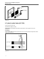
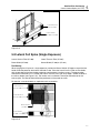
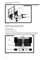
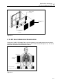
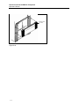
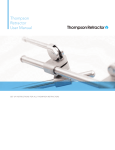
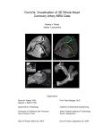
Nuclear Associates
®
CLEAR-Pb
Transparent X-Ray Compensation Filters
For Spinal Radiography
User Manual
February 2005
Manual No. 38609 Rev. 2
©2004, 2005 Fluke Corporation, All rights reserved.
All product names are trademarks of their respective companies
(Blank page)
Table of Contents
Section 1:
1.1
General Information ................................................................. 1-1
Section 2:
2.1
Applications & Specifications ........................................................ 2-1
Applications & Specifications ....................................................................... 2-1
Section 3:
3.1
Filter Holder Mounting Instructions ................................................ 3-1
Filter Holder Mounting Instructions .............................................................. 3-1
Section 4:
4.1
Filter Positioning (General) ............................................................ 4-1
Filter Positioning (General) .......................................................................... 4-1
Section 5:
5.1
5.2
5.3
5.4
5.5
5.6
5.7
5.8
5.9
5.10
5.11
5.12
5.13
Detailed Filter Positioning .............................................................. 5-1
AP Full Spine 13 cm and Under (Small to Average Patient) (72” FFD) ....... 5-1
AP Full Spine 14-19 cm (Above Average Patient) (72” FFD)....................... 5-2
AP Full Spine 20-25 cm (Large Patient) (72” FFD) ...................................... 5-4
AP Full Spine Over 25 cm (Very Large Patient) (72” FFD) .......................... 5-5
AP Lateral Cervical Spine (72” FFD)............................................................ 5-6
Lateral Thoracic Spine (40” FFD) ................................................................ 5-7
Lateral Full Spine (Single Exposure)............................................................ 5-8
AP Thoracic Spine (40” FFD)....................................................................... 5-9
AP Erect Abdominal Examination (40” FFD).............................................. 5-10
Lateral Lumbar Spine (L5-S1) Interspace (30” FFD) ................................. 5-11
Slim Lateral Spot for C7 (30” FFD) ............................................................ 5-12
Shoulder (40” FFD) .................................................................................... 5-13
Ribs (40” FFD) ........................................................................................... 5-14
Introduction .................................................................................................. 1-1
i
(Blank page)
General Information
Introduction
1
Section 1
General Information
1.1 INTRODUCTION
CLEAR-Pb Compensation Filters are made of a lead-plastic material that is 30% lead by weight. Since
lead is an efficient absorber of x-rays, the filters will attenuate the x-ray beam. By varying the shape and
thickness of the filters, many combinations of filtering action can be achieved...from almost complete
attenuation to full penetration. (See Figure 1-1.)
Figure 1-1
Filters Attenuate X-ray Beam to Provide Even Exposure Throughout Image Area
Figure 2-2
Collimator with Filter Holder (57-426) and AP/PA Wedge (57-405) in Place
1-1
Nuclear Associates CLEAR-Pb Transparent
Operators Manual
CLEAR-Pb Filters are transparent and lightweight. By means of our "Quick-Stik" system of magnetic
strips on the filters, and a filter holder that slides into the collimator's accessory tray, the filters can be held
firmly in place and repositioned instantly. (See Figure 2-2) You can see and adjust the area and/or degree
of filter coverage as necessary. Last-minute positioning checks of the patient, x-ray collimator, and filters
are possible, thanks to the filter transparency. Selected-area beam shaping has never been so simple
and effective.
CLEAR-Pb Filters should be used with a rare-earth film/screen combination to improve image quality and
keep patient exposure to a minimum. CLEAR-Pb Compensation Filters are not compatible with gradient
speed intensifying screens. Consult your film manufacturer for the proper film/screen combination. This
instruction manual provides typical suggested procedures for using CLEAR-Pb Compensation Filters.
However, individuals may modify this technique to suit their own requirements.
1-2
Applications and Specifications
Applications and Specifications
2
Section 2
Applications & Specifications
2.1 Applications & Specifications
The filters and accessories are available individually or as a set (57-445). The 57-445 CLEAR-Pb X-Ray
Compensation Filter Set includes a multi-purpose AP/PA wedge filter (72" FFD), a lateral cervical filter, a
lateral thoracic filter, a pediatric and adult gonad shield, a breast shield assembly, two AP/PA build-up
filters (one thick, one thin), a filter holder, and two mounting plates. A 40" FFD AP/PA wedge Filter is
optional. Filters purchased individually require a filter holder (56-426) to make them compatible with the xray collimator. One filter holder (with mounting plates) is recommended for each x-ray machine. All Filters
have magnetic mounting strips at each end to attach to the matching steel rails on the filter holder.
AP/PA Wedge Filter (72" FFD)
Model 57-405: Size 6 ½” long x 2 ¼” wide x 3/8" thick; weighs 6 oz.
AP/PA Wedge Filter (40” FFD)
Model 57-415: Identical to Model 57-405 except that it is 4-1/8" wide; weighs 10 oz.
Lateral Cervical Filter (72" FFD)
Model 57-406: 6 ½" long x 1 ¼" wide x 3/8" thick; weighs 4 oz.
Lateral Thoracic Filter (72" FFD)
Model 57-407: 6 ½" long x 1 ¼" wide x 3/8" thick; weighs 4 oz.
Breast Shields
Model 57-409: 3" long x 3" wide x 1/8" thick; weighs 2 oz. Will attach to Model 57-426 filter holder with or
without the use of a filter (set of 2 pieces).
Build-Up Filter AP/PA (Thin)
Model 57-430: 6 ½" long x 1 ¼" wide x 1/8" thick. Has magnetic tape on one side, steel on the opposite
side, to allow filter stacking; weighs 2 oz.
Build-Up Filter AP/PA (Thick)
Model 57-434: 6 ½" long x 1 ¼" wide x 9/32" thick. Has magnetic tape on one side, steel on the opposite
side, to allow for filter stacking; weighs 3 oz.
Filter Holder
Model 57-426: Clear plastic, 6 ½" wide x 5 ½" long x ¼" thick. Has two steel rails, 1" wide x 5 ½" long, for
positioning filters and shields. Only one filter holder is needed per x-ray machine.
Mounting Plates
Model 57-411: Clear plastic, 9" long x 9" wide x 1/16" thick. Attached to filter holder with screws. Easily
cut to fit collimator assembly. Two mounting plates are included with each filter holder assembly.
2-1
Nuclear Associates CLEAR-Pb Transparent
Operators Manual
Gonad Shield
Adult, Model 57-408: 6 ½" long x 1” wide x 1/16" thick. Has a shamrock-shaped, 0.030" thick lead shield
made up of three overlapping circles, each ½" diameter; weighs ½ oz.
Gonad Shield
Pediatric, Model 57-444: 6 ½" long x 1" wide x 1/16" thick. Has shamrock-shaped, 0.030" thick lead shield
made of three overlapping circles, each ¼' diameter; weighs ¼ oz. Also for imaging sacroiliac region of
adult female.
Filter
Model No.
Applications
Length x Width
Max. Thickness
Trough Width
Configuration
Filter Materials
Plastic
Lead-Plastic
Magnetic Tape
2-2
AP/PA
(72” FFD)
57-405
Full spine,
AP or PA
AP or oblique
esophagram
Lateral chest
AP/PA
(40” FFD)
57-415
Full spine,
AP or PA
6.5” L x 2.25” W
0.1”
˙
6.5” L x 4.125” W
0.1”
˙
Lateral
Thoracic
57-407
Lat. full spine
Oblique or AP
esophagram
(obese patients)
Angiography of
neck, lower head
(may need 2
filters)
6.5” L x 1.25” W
0.15”
˙
Lateral
Cervical
57-406
Lat. cerv. spine
Lat. full spine
(with 57-407 Filter)
Lateral aortic arch
6.5” L x 1.25” W
0.3”
˙
Applications and Specifications
Applications and Specifications
Filter
Model No.
Applications
Length x Width
Max. Thickness
Build-Up
(Thin)
57-430
Additional
Filtration to even
out density in
cervical area.
6.5” L x 1.25” W
0.125”
2
Build-Up
(Thick)
57-434
Additional filtration
to even out density
in cervical area.
Breast
Shields
57-409
Full-body shielding when imaging the full
spine. Permits vertical and horizontal
adjustment of shielded area.
6.5” L x 4.125” W
0.28”
3” L x 3” W
0.12”
Configuration
Filter Materials
Plastic
Lead-Plastic
Magnetic Tape
Shield
2-3
Nuclear Associates CLEAR-Pb Transparent
Operators Manual
(Blank page)
Filter Holder Mounting Instructions
Filter Holder Mounting Instructions
3
Section 3
Filter Holder Mounting Instructions
3.1 Filter Holder Mounting Instructions
If the collimator housing has an accessory tray, the two 9" x 9" X 1/16" acrylic mounting plates (held
together by 4 screws) should be cut to fit the rails of the tray (Figure 3-2). If the tray channel is less than
1/8" wide, only one of the mounting plates is required. The other should be removed and retained as a
spare.
To separate the filter holder from the mounting plate(s), remove the four small screws holding them
together (Figure 3-1). Carefully measure the collimator's accessory tray and mark one or both of the
mounting plates for cutting. A cardboard template is recommended as a cutting guide. Make a trial fitting
with the template before cutting the plastic to ensure that the filter holder will be in the proper position on
the mounting plate. If the final shape of the mounting plate is not square, be sure to check for proper
longitudinal orientation of the filter holder (Figure 3-2).
To cut the plastic mounting plate(s), use a plastic scoring knife. Cut each plate separately. Score the
plastic at the desired locations, making sure that each score runs the full length (width) of the plate. Make
the scores deep by going over each scratch several times.
Next, place the scored plate over the edge of a table, with the score mark on top and exactly above the
edge. Hold the plastic sheet flat to the table top with one hand. With the other hand, bend the
overhanging part of the plastic sheet down. If the score mark lines up exactly at the table edge, the
overhanging piece will break cleanly at the mark.
Check that the mounting plate slides easily into the accessory tray. To make any fine adjustments needed
for a proper fit, use a file or fine sandpaper.
Re-attach the filter holder to the mounting plate(s), and insert the assembly into the collimator's accessory
tray (Figure 3-2). If your collimator does not have an accessory tray, the filter holder may be mounted with
self-stick Velcro-type material. This attachment kit (Model 57-426-1100) is available from Fluke
Biomedical.
If the steel rails on the filter holder intrude into the x-ray field of view, unscrew the rails and turn them
around (Figure 3-3). Since the screw holes in these rails are off center, turning the rails will set them 3/4"
further apart.
If desired, the magnetic tape on some or all of the filters can be cut to match the new position of the
holder rails. Using a sharp knife, cut through the magnetic tape (on each side of the filter) in a line parallel
to, and 3/8” from, the inner edge. Remove this 3/8" strip, leaving a 5/8" tape strip along the outer edge of
the filter, which matches the new position of the filter holder rails.
The use of the filters and holder is not changed by the above procedure.
3-1
Nuclear Associates CLEAR-Pb Transparent
Operators Manual
Figure 3-1.
Screws Attach Mounting Plates to Filter Holder
Cut mounting plates to size
of accessory tray.
Filter holder, cut to proper
fit.
It slides into rails of
collimator’s accessory tray.
Beam exit window.
Figure 3-2.
Figure 3-3.
3-2
Turning the Steel Rails Increases Spacing Between Them
Filter Positioning (General)
Filter Positioning (General)
4
Section 4
Filter Positioning (General)
4.1 Filter Positioning (General)
This section contains a general description of filter positioning. Read it thoroughly before continuing.
When performing examinations with 72" FFD, a 14" x 36" cassette and preferably rare-earth intensifying
screens, proceed as described below. Sectional or multiple view radiographs on 14” x 17" or smaller films
may also be taken with the same filter orientation.
1. Position the patient, cassette, and x-ray tube as usual.
2. Attach the appropriate filter to the filter holder by the "Quick Stik” magnetic system. The magnetic
tape on the filters should align with the steel rails on the filter holder assembly. Adjust to the proper
height by sliding it up and down. The transparency of CLEAR-Pb filters allows the use or the
collimator light. However, shadow lines or the filter edges are clearly identifiable to aid in correct
placement. Either side of the filter can be outward.
3. Position the Breast Shields on top of the filter by attaching the steel side of the Breast Shields to the
magnetic mounting material at both sides of the filter.
Please Note: The Breast Shields may be used without a filter by simply attaching the magnetic side
of the Breast Shields to the filter holder rails.
Also, when using Build-Up Filters (57-430 and/or 57-434), you might prefer first attaching the Breast
Shields (magnetic side) to the filter holder rails, then positioning the AP/PA Filter over the Breast
Shields, and attaching the Build-Up Filter (metal side) over the AP/PA Filter.
4. Turn on the collimator light and position the filter so that the top edge of its shadow is at the level of
the external auditory meatus.
5. Position the Gonad Shield on the steel rails, using the shadow projected on the patient. Apply the
shamrock-shaped lead shield, with the single leaf pointing cephalad for male patients and caudad
for females.
NOTE
The inferior aspect of the sacroiliac joints will be
blocked on females. This does not apply for use on
males.
6. When radiographing the sacroiliac region of an adult female, use the smaller-diameter Pediatric
Gonad Shield (57-444).
7. Double check the filter position before exposing the film.
4-1
Nuclear Associates CLEAR-Pb Transparent
Operators Manual
(Blank page)
Detailed Filter Positioning
AP Full Spine 13 cm and Under (Small to Average Patient)(72” FFD)
5
Section 5
Detailed Filter Positioning
5.1 AP Full Spine 13 cm and Under (Small to Average Patient)
(72”FFD)
Breast Shields (57-409)
AP/PA Wedge Filter (57-405)
Gonad Shield (57-408) or (57-444)
For smaller patients, position the filter 1" above the level of the external auditory meatus. This will result in
reduced (filtered) exposure to the neck and upper chest (See Figure 5-1).
The measurement is taken in the AP position at the level of the third lumbar vertebra.
AP/PA Filter
(57-405)
Breast Shields
(57-409)
Gonad Shield
(57-408) or
(57-444)
Figure 5-1.
5-1
Nuclear Associates CLEAR-Pb Transparent
Operators Manual
AP/PA Filter
(57-405)
Breast Shields
(57-409)
Gonad Shield
(57-408) or
(57-444)
Figure 5-2.
5.2 AP Full Spine 14-19 cm (Above Average Patient) (72"
FFD)
AP/PA Filter (57-405)
Build-Up Filter (Thin) (57-430)
Breast Shields (57-409)
Adult Gonad Shield (57-408) or Pediatric Gonad Shield (57-444)
For above average patients, position the AP/PA (57-405) filter 1" above the level of the external auditory
meatus. Place the Breast Shields (57-409) on top of the AP/PA wedge (57-405). Place the Thin Build-Up
Filter (57-430) on top of the Breast Shields, with the top edge of the filter at the mid-portion of the chin
(midway between the inferior alveolar border and the mental protuberance) (See Figure 5-3). The
purpose of the Build-Up Filter is to increase the attenuation of the x-ray beam in the cervical area. This is
necessary because exposure factors will have to be adjusted to properly expose the lumbar area, due to
increased abdominal density. The measurement is taken in the AP position at the level of the third lumbar
vertebra
NOTE
When using the Build-Up Filters, always position
the steel slide against the magnet. Magnet against
magnet will result in filter movement due to
repelling magnetic fields.
5-2
Detailed Filter Positioning
AP Full Spine 14-19 cm (Above Average Patient)(72” FFD)
5
AP/PA Filter
(57-405)
Thin Build-Up Filter
(57-430)
Breast Shield
(57-409)
Gonad Shield
(57-408) or (57-444)
Figure 5-3.
AP/PA Filter
(57-405)
Breast Shields
(57-409)
Thin Build-Up
Filter (57-430)
Gonad Shield
(57-408) or
(57-444)
When using Build-Up Filter (57430), you might prefer first
attaching the Breast Shields
(magnetic side) to the filter
holder rails, then positioning
the AP/PA filter over the Breast
Shields, and attaching the
Build-Up Filter (metal side) over
the AP/PA Filter.
Figure 5-4.
5-3
Nuclear Associates CLEAR-Pb Transparent
Operators Manual
5.3 AP Full Spine 20-25 cm (Large Patient) (72" FFD)
Breast Shields (57-409)
Build-Up Filter (Thin) (57-430)
AP/PA Wedge Filter (57-405)
Gonad Shield (57-408) or (57-444)
Position the top edge of the AP/PA (57-405] Filter at the level of the external auditory meatus. Attach the
Breast Shields to the AP/PA Wedge Filter bilaterally. Place the Thin Build-Up Filter (57-430] on top of the
Breast Shields, at the base of the nose (see Figure 5-5). The measurement is taken in the AP position at
the level of the third lumbar vertebra.
Thin Build-Up Filter
(57-430)
AP/PA Filter
(57-405)
Breast Shield
(57-409)
Gonad Shield
(57-408) or (57-444)
Figure 5-5.
AP/PA Filter
(57-405)
Breast Shields
(57-409)
Thin Build-Up
Filter (57-430)
Gonad Shield
(57-408) or
(57-444)
5-4
When using Build-Up Filter (57430), you might prefer first
attaching the Breast Shields
(magnetic side) to the filter
holder rails, then positioning
the AP/PA filter over the Breast
Shields, and attaching the
Build-Up Filter (metal side) over
the AP/PA Filter.
Detailed Filter Positioning
AP Full Spine 20-25 cm (Very Large Patient)(72”FFD)
5
Figure 5-6
5.4 AP Full Spine Over 25 cm (Very Large Patient) (72" FFD)
Breast Shields (57-409)
72" AP/PA Wedge Filter (57-405)
Build-Up Filter (Thick) (57-434)
Build-Up Filter (Thin) (57-430)
Gonad Shield (57-408) or (57-444)
Position the top edge of the AP/PA Filter at the level of the external auditory meatus. Attach the Breast
Shields on top of the AP/PA Wedge Filter. Place the Build-Up Filter (thick) on top of the Breast Shields,
with the top edge at the base of the nose. Position the Build-Up Filter (thin) on top of the Thick Build-Up
Filter to provide additional filtration for the odontoid process (see Figure 5-7). An increase in technique is
necessary as the patient measurement increases. The measurement is taken in the AP position at the
level of the third lumbar vertebra.
Thin Build-Up Filter
(57-430)
Thick Build-Up Filter
(57-434)
AP/PA Filter
(57-405)
Breast Shield
(57-409)
Gonad Shield
(57-408) or (57-444)
Figure 5-7
5-5
Nuclear Associates CLEAR-Pb Transparent
Operators Manual
AP/PA Filter
(57-405)
Breast Shields
(57-409)
Thick Build-Up
Filter (57-434)
Thin Build-Up
Filter (57-430)
Gonad Shield
(57-408) or
(57-444)
When using Build-Up Filter (57430) and (57-434), you might
prefer first attaching the Breast
Shields (magnetic side) to the
filter holder rails, then
positioning the AP/PA filter
over the Breast Shields, and
attaching the Build-Up Filter
(metal side) over the AP/PA
Filter.
Figure 5-8
5.5 AP Lateral Cervical Spine (72" FFD)
72" Non-Bucky
Lateral Cervical Filter (57-406)
For smaller or average-size patients, no filtration is needed,
For patients with broad shoulders, the Lateral Cervical Filter (57-406) may be indicated. Position it with
the shadow of the top edge 1" above the level of the external auditory meatus. The bottom edge should
end at the level of the fourth cervical vertebra (see Figure 5-9).
Lateral Cervical
Filter (57-406)
Figure 5-9.
5-6
Detailed Filter Positioning
AP Lateral Cervical Spine (72” FFD)
5
Lateral Cervical
Filter (57-406)
Figure 5-10.
5.6 Lateral Thoracic Spine (40" FFD)
Lateral Thoracic Filter (57-407)
Breast Shields (56-409)
To best visualize the thoracic vertebrae, the humeral heads should project anterior to the thoracic spine.
This is done by having the patient place the arms in front of the body, with elbows bent and drawn
together, hands supinated perhaps resting on the IV pole to help stabilize the patient.
Attach the Breast Shields to the Filter holder assembly (magnet- to-steel). Place the Lateral Thoracic
Filter on top of the Breast Shields.
The Lateral Thoracic Filter is placed to project 1" below the axillary border (see Figure 5-11).
Breathing technique is utilized. Measurement is taken posterior to the humeral heads.
When imaging patients with kyphosis: Take measurement through the kyphosis only, to prevent
overexposure.
Collimation 7" x 17".
Slide posterior Breast
Shield out of F.O.V.
Lateral Thoracic
Filter (57-407)
Breast Shield
(57-409)
Figure 5-11.
5-7
Nuclear Associates CLEAR-Pb Transparent
Operators Manual
Breast Shields
(57-409)
Lateral Thoracic
Filter (57-407)
Figure 5-12.
5.7 Lateral Lumbar Spine (40" FFD)
Lateral Thoracic Filter [57-407)
Gonad Shield (57-408) or (57-444)
Used primarily on female patients where the hip measurement is 4-8 cm greater than the waist
measurement.
Positioning
Place the bottom edge of the filter just above the iliac crest. Take measurement through the fifth lumbar
vertebra (see Figure 5-12).
Lateral Thoracic
Filter (57-407)
Gonad Shield
(57-408 or 57-444)
Figure 5-13.
5-8
Detailed Filter Positioning
Lateral Lumbar Spine (40” FFD)
5
Lateral Thoracic
Filter (57-407)
Gonad Shield
(57-408 or 57-444)
Figure 5-14.
5.8 Lateral Full Spine (Single Exposure)
Lateral Cervical Filter (57-406)
Lateral Thoracic Filter (57-407)
Breast Shield (57-409)
Gonad Shield (57-408) or (57-444)
Positioning
When imaging the full spine in a single exposure, position the Breast Shields (57-409) on top of the filter
holder. Slide the posterior shield out of the field of view. Place the Lateral Cervical Filter on the shields,
with the top edge of the filter shadow projecting over the external auditory meatus. The bottom edge
should end at the level of C-5. Position the Lateral Thoracic Filter, with its top edge 1" below the level of
the axillary border (see Figure 5-15). The lumbar area is unfiltered. Technique should be set for the
lumbar spine. The Gonad Shield should be positioned as illustrated for males.
For females, raise the shield 4 cm cephalad and 2 cm posterior.
Lateral Cervical
Filter (57-406)
Lateral Thoracic
Filter (57-407)
Breast Shield
(57-409)
Gonad Shield
(57-408 or 57-444)
Figure 5-15.
5-9
Nuclear Associates CLEAR-Pb Transparent
Operators Manual
Breast Plate
(57-409)
Lateral Cervical
(57-406)
Lateral Thoracic
Filter (57-407)
Gonad Shield
(57-408) or
(57-444)
Figure 5-16.
5.9 AP Thoracic Spine (40” FFD)
Breast Shields (57-409)
AP/PA Full Spine Filter (57-415)
Gonad Shield (57-408) or (57-444)
Position the 57-415 (40" FFD) AP/PA Wedge Filter so that the shadow of the filter's thick edge is just
above the external auditory meatus (see Figure 5-17). The tapered section of the filter must be in the
caudad direction. Attach the Breast Shields (57-409) to both sides or the AP/PA Wedge Filter.
Thick Edge
AP/PA Filter
(57-405)
Thin Edge
Breast Shields
(57-409)
Gonad Shield
(57-408) or (57-444)
Figure 5-17.
5-10
Detailed Filter Positioning
AP Thoracic Spine (40” FFD)
5
AP/PA Filter
(57-405)
Breast Shields
(57-409)
Gonad Shield
(57-408) or
(57-444)
Figure 5-18.
5.10 AP Erect Abdominal Examination
Position the 57-405 AP/PA Wedge Filter so that the shadow of its thick edge projects over the patient's
diaphragm. Check that the thin edge of the filter is in the caudad direction (see Figure 5-19). For use on
patients with noticeable increased abdominal density.
Thick Edge
AP/PA Filter
(57-405)
Thin Edge
Gonad Shield
(57-408) or (57-444)
Figure 5-19.
5-11
Nuclear Associates CLEAR-Pb Transparent
Operators Manual
AP/PA Filter
(57-405)
Gonad Shield
(57-408) or (57-444)
Figure 5-20.
5.11 Lateral Lumbar Spine (L5-S1) Interspace (30” FFD)
Lateral Thoracic Filter (57-407)
Position as the diagram indicates, with the Filter on an angle to allow the top edge to be positioned
through the body of the first lumbar vertebra and the bottom edge through the body of the fourth lumbar
vertebra (see Figure 5-21).
Lateral Thoracic
Filter (57-407)
Figure 5-21.
5-12
Detailed Filter Positioning
Lateral Lumber Spine(L5-S1) Interspace (30” FFD)
5
Lateral Thoracic
Filter (57-407)
Figure 5-22.
5.12 Slim Lateral Spot for C7 (30" FFD)
Lateral Thoracic Filter (57-407)
Filter the cervical spine above C7 for a more even density throughout the spine. Position the patient in the
lateral position. Raise the arm closest to the film, drawing it back under his head as far as possible. Have
the patient drop the opposite shoulder by moving his arm posterior to allow the head of the humerus to
move posterior. Position the filter on an angle so that the bottom edge of the filter covers the sixth cervical
vertebra (see Figure 5-23). Increase technique for C7 as required.
Lateral Thoracic
Filter (57-407)
Figure 5-23.
5-13
Nuclear Associates CLEAR-Pb Transparent
Operators Manual
Lateral Thoracic
Filter (57-407)
Figure 5-24.
5.12 Shoulder (40" FFD)
Lateral Thoracic Filter (57-407)
Position the patient as usual. Place the Lateral Thoracic Filter so that its bottom edge covers the
acromioclavicular joint (see Figure 5-25). There is no change in technique.
Lateral Thoracic
Filter (57-407)
Figure 5-25.
5-14
Detailed Filter Positioning
Shoulder (40” FFD)
5
Lateral Thoracic
Filter (57-407)
Figure 5-26.
5.13 Ribs (40" FFD)
40" AP/PA Filter (57-405)
The 40" AP/PA Filter is used to even out densities in the chest cavity as it increases in size. The thin end
of the filter is in the caudad direction (see Figure 5-27). How low the filter is positioned depends on the
shape of the patient.
NOTE
Filter is suggested for above-diaphragm application
only.
Thick Edge
AP/PA Filter
(57-405)
Thin Edge
Figure 5-27.
5-15
Nuclear Associates CLEAR-Pb Transparent
Operators Manual
AP/PA Filter
(57-405)
Figure 5-28.
5-16
(Blank page)
Fluke Biomedical
Radiation Management Services
6045 Cochran Road
Cleveland, Ohio 44139
440.498.2564
120 Andrews Road
Hicksville, New York 11801
516.870.0100
www.flukebiomedical.com/rms