1
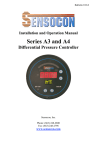
Installation and Operation Manual 2.2 Pressure Connection Two 3/16” pressure connections are located on the back of the unit, labeled “High” and “Low”. For best results, connect 3/16” I.D. push on tubing to the pressure connections. If the High connection has a greater absolute value than the Low connection, the front display will give a positive value. If the HI connection has a lower absolute value than the LO connection, the front display will give a negative value. 2.3 Electrical Connections Series A1 & A2 3.2 Key Function The A1 and A2 have four buttons located on the face of the gauge for set-up and calibration. There is a Span, Zero, Units, and Lock button. The Units button changes the unit of measure and the Lock button locks and unlocks the keypad on the gauge. Span and Zero are used for calibration (see calibration section 4.2). By simultaneously pressing the span and zero buttons for 3 seconds, the unit will be switched from internally sourcing the power for the current loop to requiring an external power supply. 4. OTHER FEATURES 4.1 Opti-Link Optilink™ is an infrared communications technology that allows the user to upload and download program parameters from one unit to another with a programming key. By using the PK-01 universal programming key, the user may program one unit, download those parameters to the universal programming key and then upload that same program from the key to other controls. By using a PK-02 lockout programming key, a user may completely lock (or unlock) the face keypad of the control to eliminate the possibility of unwanted tampering of the control. 4.2 Calibration Periodically, it may be necessary to recalibrate the gauge to maintain the accuracy of the product. To “zero” the gauge, remove the pressure connections from both pressure ports and hold the zero button for 3 seconds. To “span” the gauge, apply the full scale pressure to the High pressure port and hold the span button for 3 seconds while maintaining the full scale pressure. Pressure must be maintained at zero or span during the calibration process. Because the span and zero are non interactive, this should complete the calibration process. NOTES: 1. Supply Voltage is universal from 16-265 VAC or VDC 2. For internally sourced 4-20 mA loop, maximum loop resistance is 750 Ω; for externally sourced loop at 36 VDC, maximum loop resistance is 1800 Ω. 3. Isolation: 4-20 mA: 5000 VAC to all other inputs and outputs The 4-20 mA process output is set to give a linear output from 0 to the full scale pressure range of the product. Other pressure spans such as bidirectional or reduced ranges can be scaled with an OptiLink™ programming key, consult the factory for details. 4.3 Limited Warranty 3. OPERATION 3.1 Display The series A1 displays pressure on a 4 digit LED display and will show 3 or 4 digits depending on the range and accuracy of the product. Negative pressure will be indicated by a negative sign before the numerical indication. Units of measure are displayed above the 4 digit LED display by LED indicators. The Series A2 adds a process arch, which is designed to mimic the indicating needle of a mechanical gauge. The process arch will light up from left to right as the pressure moves away from zero. Process Arch (A2 only) Unit Indication Negative Indication (863) 248-2800 LED Pressure Indication www.sensocon.com LIMITED WARRANTY SENSOCON warrants its products to be free from defects in materials and workmanship for a period of one (1) year from the date of shipment, subject to the following terms and conditions: Without charge, SENSOCON will repair, replace, or refund the purchase price at SENSOCON’s option products found to be defective in materials or workmanship within the warranty period; provided that: i. the product has not been subjected to abuse, neglect, accident, incorrect wiring not our own, improper installation or servicing, or use in violation of labels or instructions provided by SENSOCON; ii. the product has not been repaired or altered by anyone except SENSOCON; iii. the maximum ratings label and serial number or date code have not been removed, defaced, or otherwise changed; iv. examination discloses, in the judgment of SENSOCON, the defect in materials or workmanship developed under normal installation, use and service; and v. SENSOCON is notified in advance of and the product is returned to SENSOCON transportation prepaid before expiration of the warranty period. THIS EXPRESS LIMITED WARRANTY IS IN LIEU OF AND EXCLUDES ALL OTHER REPRESENTATIONS MADE BY ADVERTISEMENTS OR BY AGENTS AND ALL OTHER WARRANTIES, BOTH EXPRESS AND IMPLIED. THERE ARE NO IMPLIED WARRANTIES OF MERCHANTABLILTY OR OF FITNESS FOR A PARTICULAR PURPOSE FOR GOODS COVERED HEREUNDER. 2