1
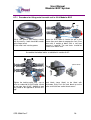
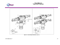
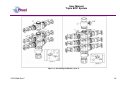
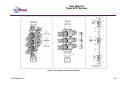
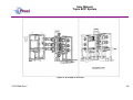
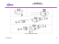
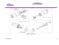
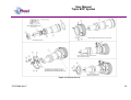
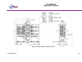
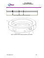
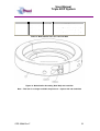
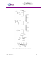
User Manual
Modular BOP System
Figure 2: Modular Map ..................................................................................... 3
Figure 3: BOP Dimensions .............................................................................. 5
Figure 4: Section through BOP rams (closed position) .................................... 6
Figure 5: Equalisation Layout........................................................................... 9
Figure 6: Equalisation Operation 1................................................................. 10
Figure 7: Equalisation Operation 2................................................................. 11
Figure 8: Equalisation Operation 3................................................................. 12
Figure 9: Correct lubrication for storage ......................................................... 14
Figure 10: Qualified Operating Envelope ....................................................... 18
Figure 11: Accessing the rams....................................................................... 21
Figure 12: BOP Wireline Rams ...................................................................... 21
Figure 13: BOP Shear Rams ......................................................................... 22
Figure 14: Example of Two bolted collar and lock block ................................ 24
Figure 15: Example of Single bolted collar and lock block ............................. 24
Figure 16: Assembling the Modules (Part 1) .................................................. 27
Figure 17: Assembling the Modules (Part 2) .................................................. 28
Figure 18: Assembly of the Equalising Block ................................................. 29
Figure 19: Assembly of the Frame ................................................................. 30
Figure 20: Modular Body Assembly ............................................................... 31
Figure 21: Actuator (Part 1)............................................................................ 32
Figure 22: Actuator (Part 2)............................................................................ 33
Figure 23: Modular BOP 193-3568-HV0 (Part 1) ........................................... 39
Figure 24: Modular BOP 193-3568-HV0 (Part 2) ........................................... 40
Figure 25: Modular Body 196-3145-HV0 ....................................................... 42
Figure 26: Modular Actuator 190-2476-HV0 .................................................. 44
Figure 27: Wireline Ram Assy 190-3863-HH0 ............................................... 45
Figure 28: Shear Ram Assy 190-3862-HH0 .................................................. 46
Figure 29: Bottom Sub Assembly................................................................... 47
Figure 30: Top Sub Assembly ........................................................................ 48
Figure 31: Equalisation Assy 190-2806-HV0 ................................................. 49
Figure 32: Bolted Collar Assembly (Single Bolt) 196-3497-HS0 .................... 50
Figure 33: Bolted Collar Assembly (Dual Bolt) 196-3150-HS0 ....................... 51
Figure 34: Equalizing Check Valve Assy 193-4023-HV0 ............................... 53
OPS-3568-Rev F
iii