1
21
2.1.5 Supports and loading
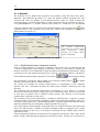
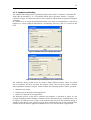
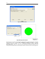
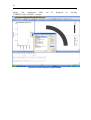
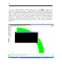
The supports and loading can be a specified using the menu ‘Data | Conditions’. We define the
fixed nodes by checking X-, Y-, Z-Constrains and the type of geometry ‘Surface’. Using the
command ‘Assign’ we selects the end face of the cantilever and finish the assignment of support
conditions.
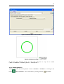
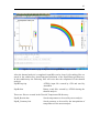
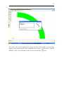
In a similar way we assign the Point-displacement at the node of load application. The load is
applied as a vertical imposed displacement. Consequently the force value is a reaction at this
node.
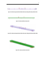
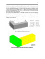
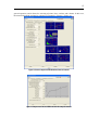
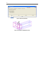
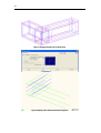
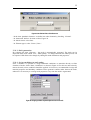
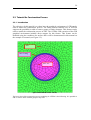
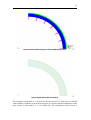
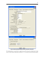
Figure 23: Definition of the surface support in all directions
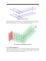
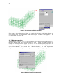
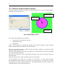
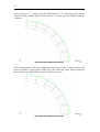
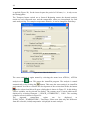
Figure 24: Definition of prescribed displacement in vertical direction
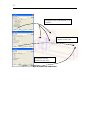
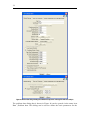
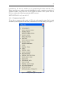
The conditions dialog of GiD can be also used to define ATENA monitors. These are special
type of conditions that does not affect the analysis results. They are merely used to monitor
certain quantities during the analysis. In this example, the following monitors will be specified:
•
Maximal crack width
•
Displacement at the point of load application
• Reaction at the point of load application
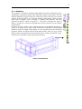
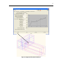
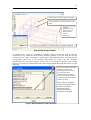
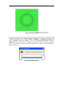
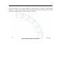
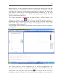
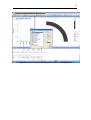
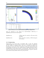
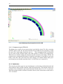
The definition process of the above conditions and monitors is described in Figure 26. The
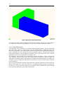
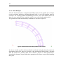
resulting assignment of the boundary conditions can be checked using the command Draw | All
Conditions | Exclude local axis, which can be located at the bottom of the Conditions dialog. It
should be noted that it is also possible to apply these conditions directly on the generated finite
element model, but then the applied conditions are lost every time the mesh is regenerated.