1
OUTPUT SIGNALS
RS-232 / RS-485 Digital Output Signal
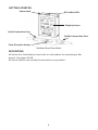
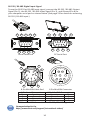
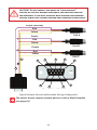
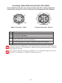
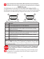
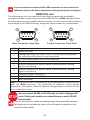
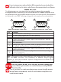
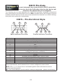
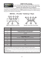
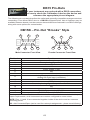
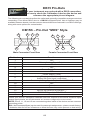
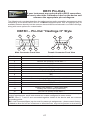
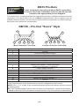
To use the RS-232 or RS-485 output signal, it is necessary to connect the RS-232
/ RS-485 Output Signal (Pin 5), the RS-232 / RS-485 Input Signal (Pin 3), and
Ground (Pin 8) to your computer serial port as shown on page 8. (See page 22
for details on accessing RS-232 / RS-485 output.)
Standard Voltage (0-5 Vdc) Output Signal
M-Series flow meters equipped with a 0-5 Vdc (optional 0-10 Vdc) will have this
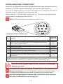
output signal available on Pin 6. This output is generally available in addition to
other optionally ordered outputs. This voltage is usually in the range of 0.010
Vdc for zero flow and 5.0 Vdc for full-scale flow. The output voltage is linear
over the entire range. Ground for this signal is common on Pin 8.
Optional 0-10 Vdc Output Signal
If your meter was ordered with a 0-10 Vdc output signal, it will be available on
Pin 6. (See the Calibration Data Sheet that shipped with your meter to determine
which output signals were ordered.) This voltage is usually in the range of 0.010
Vdc for zero flow and 10.0 Vdc for full-scale flow. The output voltage is linear over
the entire range. Ground for this signal is common on Pin 8.
Optional Current (4-20 mA) Output Signal
If your meter was ordered with a 4-20 mA current output signal, it will be
available on Pin 1. (See the Calibration Data Sheet that shipped with your meter
to determine which output signals were ordered.) The current signal is 4 mA at
0 flow and 20 mA at the meter’s full scale flow. The output current is linear over
the entire range. Ground for this signal is common on Pin 8. (Current output
units require 15-30Vdc power.)
Optional 2nd Analog Output Signal
You may specify an optional 2nd analog output on Pin 2 at time of order. (See
the Calibration Data Sheet that shipped with your meter to determine which
output signals were ordered.) This output may be a 0-5 Vdc, 0-10 Vdc, or
4-20 mA analog signal that can represent any measured parameter. With this
optional output, a meter could output the mass flow rate (0-5 Vdc on pin 6) and
the absolute pressure (0-5 Vdc on pin 2).
If your device is CSA/ATEX approved or equipped with the optional six pin
industrial connector, please contact Alicat.
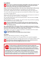
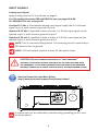
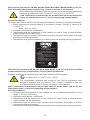
CAUTION! Do not connect this device to “loop powered’”
systems, as this will destroy portions of the circuitry and void
the warranty. If you must interface with existing loop powered
systems, always use a signal isolator and a separate power supply.
11