1
23rd August 2015
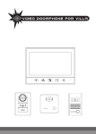
1, 7'' LCD Indoor Monitor 2, 16 different musical chimes,
all with adjustable volume. 3, IR function 4,
Size:230X150X28MM 5, Power:14V,1.2A
OCC-316
1, 1/3 CMOS Image Sensor 2, CMOS 300000 Pixel 3, 6pcs
infrand LEDS 4, Wide angle 150 degree.Metal Design
OCC-212
2
Contents
1.
2.
3.
4.
5.
6.
7.
8.
9.
10.
11.
12.
13.
14.
15.
Introduction...................................................... 4
Outdoor unit..................................................... 5
Indoor unit........................................................ 6
Basic Operation...............................................8
Wiring Diagram..............................................10
Intercom System Installation....................... 12
Camera installation....................................... 13
Monitor wall handling installation................15
Specifications................................................ 16
Operating conditions.................................... 17
Maintenance.................................................. 17
Warnings........................................................ 17
Parts................................................................18
Technical support.......................................... 18
Notes...............................................................19
Note
Note:
Due to ongoing product development and quality improvements,
it is possible that the illustrations shown in this manual differ slightly from
the actual product.
3
1. Introduction
This is a flexible , multifunctional, strong anti-jamming, high secrecy
product .The product has a modern appearance, user-friendly design,
and simple to use individual control buttons. Image is very clear and with
its simple installation it is an ideal home security product which will make
for a safer home environment.
It has a 7 inch TFT digital display screen and a selection of 16
different musical chimes, all with adjustable volume.
Photos taken with the outdoor camera can be viewed indoor, also
have date and time on the photo that be taken. and you can monitor the
outdoor scene at any time. With infrared lights, night visitors can also be
recognized. Indoor unit can give outdoor unit power supply, convenient
and saving energy .
A outdoor unit can support multiple indoor unit, make you at home
can be seen at the outdoor environment.
Screen Display time, and date
Pass CE and ROHS certification
Thank you for your support for our product, your satisfaction is our
aim.
4
2. Outdoor Unit
Key components Description:
(1). Camera lens (sends caller’s image to indoor unit)
(2). Microphone (sends caller’s voice to indoor unit)
(3). Infrared light (enables the camera to function at night)
(4). Speaker (allows the caller to hear the home owner’s voice)
(5). Call button (Used to call the home owner and turn on the camera)
(6). power cable (+)
(7). Audio cable
(8). GND
(9). video cable
(10). Lock cable(+)
(11). Lock cable (-)
5
3. Indoor Unit
6
parts and buttons description:
(1) 7 inch TFT digital display screen (Shows the image of external view
and visitors)
(5) Speaker: Plays the selected musical chime and caller’s voice
(6) Power indicator LED (when the power is connected the LED indicator
light will keep on )
(4) work indicator LED(in display open cases, the LED light will keep on )
(5) .Adjust the brightness button(adjust the video brightness and music)
(6) .Adjust the chroma button(adjust the video chroma and volume)
(7).Monitor button: Enables monitoring the external view without a caller
(8).Unlock button: in the intercom model can open the electric lock
(9).Microphone: Sends the home owner’s voice to the outdoor unit
(10).Talk button: Enables intercom with outdoor unit
(11).Outdoor unit and indoor unit connection socket.
(12).Indoor unit and indoor unit connection socket.
(13).Power connection socket.
(14).Power connection socket.
4.operating instructions
Note: the following operation must meet situation which no abnormalities
and normal .
How to turn to sleep model?
1)How
◆ When outdoor unit call the indoor unit , press ''talk button'' two times into the sleep
model ,or after 15 seconds automatic into sleep mode .
◆ When indoor unit in video model ( no the outdoor unit call situation ) press ''
monitor button '' into sleep model , or after 90 seconds automatic into sleep mode
how to enter into intercom model
2)how
In sleep model ,when press call button of outdoor unit, the chime of indoor unit
7
sounds 15 seconds,after press the “monitor”button on the indoor unit ,then press
“intercom”button,can intercom with outdoor unit(intercom time can keep 90
seconds).when talk,you can press “unlock ”button to open the door, press ‘talk
“or”monitor”button ,then exit the intercom mode
How to monitor
3)How
If the outdoor unit didn't call, users need through the indoor unit monitoring outdoor
conditions, then press "monitoring key" , can see outdoor conditions.the monitor time
can keep 90 seconds ,press “monitor”again,then close monitor.
How to unlock
4)How
Only when in intercom mode ,it can unlock . Press ''unlock button ''
The bell selection and volume adjustment and exit.
5)The
To ensure the power supply is normal :
① .When indoor unit at any mode, can press "Adjust the brightness button" (adjust the
video brightness and music)to selection from 16 pcs musics, press the ''talk button
''exit the music choice .
②
When indoor unit at any mode, can press Adjust the chroma button(adjust the
video chroma and volume) to adjust the volume , press the ''talk button ''exit the
volume choice .
8
5.Wiring Diagram
1. One camera to one monitor
One camera to two monitor
2.
2.O
9
3 Cable Specifications
A: cable of the maximum length for the indoor unit to outdoor unit
B: cable of the maximum length for the indoor unit to indoor unit
C: cable of the maximum length for the lock to outdoor unit
10
0.2MM
0.5MM
1.0MM
A
30M
50M
100M
B
20M
50M
100M
C
2M
3M
5M
Color
Cable function
1
Yellower
Video
2
Black
GND
3
Green
Audio
4
Red
Power
5
Blue
Signal
Color
Cable function
1
Yellower
Video
2
Black
GND
3
Green
Audio
4
Red
Power
6. Intercom System Installation
Mounting Position,
Door Station
The
standard
height
for the
door
station
installation is 1450mm. (note: this depends on
the individual’s height), so the centre of the lens
coincides with the line of vision. The distance
between the ground level and the bottom of the
door station is approximately 1300mm.The total
field of
view of the door station lens is 90 degrees
about the horizontal axis.The maximum
distance between the caller and door station
for a clear image should be less than 750mm.
Mounting Position,
Intercom Station
The standard height for the intercom station
installation is 1300mm (note: this depends on the
individual’s height), so the centre of the monitor
coincides with the line of vision.
The distance between the ground level
and the bottom of the intercom station is
approximately 1300mm.
11
Camera installation
7.
7.C
1. keep the Power cable + - and
lock cable + - through the
Water cycle hole, keep suitable
cable enough then Fixed the 4
screw ,then install the wall
mounting of monitor
on the
wall .
2.electric lock connect at the
right end socket, the left end
socket used connect indoor
12
3,Make sure the cables is fixed
on, then fix on the front cover .
4.Fixed on the bottom 2 screw
then fixed on the 2Silicone mat
13
8. Monitor installation
1.Fixed the 2 screw, install the
wall mounting of monitor on the
wall
2.Install the monitor on the wall
mounting .
3.Connect the DC adapter to the
monitor'
14
9. Specifications
Outdoor camera
Power
DC14V (Receive
power from monitor )
Indoor monitor
Input:AC100-240V
Power
Output:DC 14V/1.2A
CMOS 300,000 pixel
Camera
View angle 150
Screen
degrees.
Illumination
6pcs Infrared light
size
103*150*30MM
50/60HZ
7” TFT
LCD:800*480
Communication
Handfree
Model
Communication
wire
Connection
Chime Melody
4-wire Connection
16Chimes
Maximum
Power
16.8W
Consumption
Dimensions
230×150 × 32mm
15
Operating conditions
10.
10.Operating
① Operating temperature range:-15°C to +55°C
② Operating humidity: less than 85%, non-condensing
11
11.. Maintenance
①
②
③
Use a soft, dry cloth to wipe and dry the machine
Switch off power to the indoor unit before cleaning
Difficult to remove dirt can be cleaned using a neutral detergent with
④
a soft towel before drying with a soft dry cloth
Do not use benzene, thinner or other organic solvents such as
gasoline to clean. These solvents may damage the machine casing
or the surface and may discolor the buttons
12. Warnings
1.
The machine should be installed in a solid, well-ventilated, dry
environment away from direct sunlight, strong magnetic field and
dust
2. Do not use chemicals to clean the surface, you should use a clean,
dry soft cloth to wipe
3. Avoid pressing several keys together
4. Only use products with these units that have been produced by our
factory. Other products may not be compatible and may not work
correctly.
5. Do not disassemble the machine without authorization. If there is a
fault that needs repair, please contact your dealer.
16
6.
Do not install or make any wire adjustment while power supply is
plugged in. It can cause electrical shock or damage to the unit.
7. Do not manually hold down hook switch to verify chime volume. It
could cause loud feedback in the handset and can lead to hearing
damage.
8. Do not mount the monitor where it could be bumped, hit, or easily
jolted.
9. In the case of electrical storms, unplug power supply from AC
outlet. It can cause fire, electrical shock, or power surge.
10. Do not install components in any of the following locations, as it may
cause the system to malfunction:
- High or extreme cold temperature area: under direct sunlight, near
equipment that varies in temperature, in front of air conditioner.
- Places subject to moisture or humidity extremes, such as
bathroom, cellar, greenhouse, etc.
- Places subject to environmental conditions, such as oil, dust,
salts, chemicals, etc.
- Places subject to constant vibration or impact.
- Places where noise generating devices, such as close to TV or radio
equipment.
11. Monitor is designed for indoor use only. Do not install outdoors.
12. Keep the equipment dry. If water should get in, wipe off
immediately. Water contains minerals that can erode electronic circuits.
13. Intercom system is not operational during a power failure.
14. Intercom system may be affected by radio frequency interference
or EMI (Electromagnetic Interference) in areas where broadcasting
station antennas are close by
17
13. Parts
□ Monitor
□ Camera
□ 14V/1.2A power (monitor )
□ User manual
□ Cable (standard configuration 1M)
Note:
Electronic lock is not included
14. Technical Support
1
Please read this user's manual carefully before installation and
use. Save this manual for future reference.
2
Please use and install in strict accordance with the user's manual. If
you meet any problems in the installation process, please call us for
technical support and consulting services.
18
15.【Notes】
(1) Our Company is committed to reform and innovation, and reserves
the right to make changes and improvements without further notice.
Illustrations in this manual are for reference only.
(2) All warranty and liability is void should you or your dealer open the
unit without authorization or remove/deface the product labeling
(3) Please ensure you carefully record and keep the Serial Number
label on the machine. It is the only means of identifying your product.
(4) Warranty: For one year from purchasing this product, we promise to
provide you with free maintenance and technical support. This excludes
damage during installation, unauthorized tampering and willful damage.
(5) Warranty periods different from this cannot be support by the
manufacturer
19
20