1
ROBO-8914VG2AR
Single Board Computer
User's Manual
Version 1.0
Copyright © Portwell, Inc., 2010. All rights reserved.
All other brand names are registered trademarks of their respective owners.
Preface
Table of Contents
How to Use This Manual
Chapter 1 System Overview ....................................................................................................... 1-1
1.1 Introduction.................................................................................................................................. 1-1
1.2 Check List ..................................................................................................................................... 1-2
1.3 Product Specification .................................................................................................................. 1-3
1.3.1 Mechanical Drawing ......................................................................................................... 1-6
1.4 System Architecture .................................................................................................................... 1-7
Chapter 2 Hardware Configuration............................................................................................ 2-1
2.1 Jumpers ......................................................................................................................................... 2-1
2.2 Connectors .................................................................................................................................... 2-4
Chapter 3 System Installation .................................................................................................... 3-1
3.1 Intel® LGA 775 Processor........................................................................................................... 3-1
3.2 Main Memory............................................................................................................................... 3-4
3.3 Installing the Single Board Computer....................................................................................... 3-5
3.3.1 Chipset Component Driver .............................................................................................. 3-5
3.3.2 Intel Integrated Graphics GMCH Chip .......................................................................... 3-5
3.3.3 On-board Fast Ethernet Controllers................................................................................ 3-6
3.3.4 On-board High Definition Audio Controller................................................................. 3-6
3.3.5 Intel Matrix Storage Manager Device ............................................................................. 3-6
3.3.6 AMT Function Installation ............................................................................................... 3-8
3.3.7 Intel Trusted Platform Module ........................................................................................ 3-8
3.4 Clear CMOS Operation............................................................................................................... 3-8
3.5 WDT Function.............................................................................................................................. 3-9
3.6 GPIO ............................................................................................................................................ 3-10
3.6.1 Pin assignment ................................................................................................................. 3-10
3.6.2 ROBO-8914VG2AR GPIO Programming Guide ......................................................... 3-11
3.6.3 Example ............................................................................................................................ 3-12
Chapter 4 BIOS Setup Information ............................................................................................ 4-1
4.1 Entering Setup -- Launch System Setup ................................................................................... 4-1
4.2 Main Menu ................................................................................................................................... 4-2
4.3 Advanced BIOS Features............................................................................................................ 4-3
4.4 PCI/PNP Resource Management............................................................................................ 4-22
4.5 Boot Configuration Features .................................................................................................... 4-24
4.6 BIOS Security Features.............................................................................................................. 4-29
4.7 Advanced Chipset Features ..................................................................................................... 4-30
4.8 Exit............................................................................................................................................... 4-39
Chapter 5 Troubleshooting ........................................................................................................ 5-1
5.1 Hardware Quick Installation ..................................................................................................... 5-1
5.2 BIOS Setting.................................................................................................................................. 5-2
5.3 FAQ ............................................................................................................................................... 5-3
Appendix A
Appendix B
Preface
How to Use This Manual
The manual describes how to configure your ROBO-8914VG2AR system to meet
various operating requirements. It is divided into five chapters, with each chapter
addressing a basic concept and operation of Single Host Board.
Chapter 1 : System Overview. Presents what you have in the box and give you an
overview of the product specifications and basic system architecture for this series
model of single host board.
Chapter 2 : Hardware Configuration. Shows the definitions and locations of
Jumpers and Connectors that you can easily configure your system.
Chapter 3 : System Installation. Describes how to properly mount the CPU, main
memory to get a safe installation and provides a programming guide of Watch Dog
Timer function.
Chapter 4 : BIOS Setup Information. Specifies the meaning of each setup
parameters, how to get advanced BIOS performance and update new BIOS. In
addition, POST checkpoint list will give users some guidelines of trouble-shooting.
Chapter 5 : Troubleshooting. Provides various useful tips to quickly get ROBO8914VG2AR running with success. As basic hardware installation has been
addressed in Chapter 3, this chapter will basically focus on system integration issues,
in terms of backplane setup, BIOS setting, and OS diagnostics.
The content of this manual is subject to change without prior notice. These changes
will be incorporated in new editions of the document. Portwell may make
supplement or change in the products described in this document at any time.
Updates to this manual, technical clarification, and answers to frequently asked
questions
will
be
shown
on
the
following
web
site
:
http://www.portwell.com.tw/.
Preface
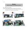
Notice
SBC Handling and Installation Notice
Handling and Installing SBC
Caution: Do not just hold any single side of the SBC; hold evenly on both sides!
Heavy processor cooler may bend the SBC when SBC being held just on one side.
The bending may cause soldering or components damaged.
Preface
Fix your SBC in System
Caution: Suggest your S.I or vendor to use a metal bracket to hold/fix the desktop or server
grade SBC to avoid the vibration damage during transportation. Heavy processor
cooler may bend the SBC when systems are during transportation without any
holder.
Example:
4U chassis :
Use L type mental or plastic or rubber bracket to hold SBC.
2U or 1U chassis: a mental bracket on the bottom of chassis to balance and
support SBC from bending.
System Overview
Chapter 1
System Overview
1.1
Introduction
ROBO-8914VG2AR, the PICMG 1.3 SHB (Single Host Board) combined with either
the Intel® Core 2 Quad processor, and with support 45nm Intel® Core 2 processor
family. The attractive Core 2 Duo processor does not only posses amazing parallel
computing power but also generates 65W TDP (Thermal Design Power). That
makes the system more powerful and reliable with dual-core processor with smaller
and quieter cooling fan.
The SHB adopted Intel® Q45 & ICH10DO chipset. The Q45 embedded Graphics
Media Accelerator 4500 is the 5th generation Intel integrated graphics controller that
supports DirectX 10, Shader model 4.0, and OpenGL 2.1. More than that, user
could utilize even higher-end, the latest PCI Express x16 interface graphics card via
backplane.
ROBO-8914VG2AR built with dual Intel® Gigabit Ethernet. Four DDR3 long DIMM
sockets support system memory up to 8GB. Six SATA 300 ports (dual ports via
backplane) support RAID 0, 1, 5, 10.
To meet bandwidth of storage and expansion cards requirement, the ROBO8914VG2AR was designed flexible with four PCI Express lanes via backplane.
Those four PCI Express lanes could be four PCI Express x1 links or one PCI Express
x4 link. Four PCI Express x1 links configuration can support more PCI Express x1
devices via backplane and one PCI Express x4 link configuration can support RAID
card or special add-on cards such as image processing board. In addition, the
flexible configuration can be leveraged with bridge on backplane to support more
PCI or PCI-X slots that benefits industries with legacy support.
Advanced Management Technology (AMT) 5.0 is feature that ROBO-8914VG2AR
equipped. This technology provides remote access capability via Intel® Gigabit
Ethernet controller. The new technology is a hardware-based solution that uses
out-of-band communication for system management access to client systems. Beside
that, the hardware and software information can be gathering by 3rd party software
then storage in SPI interface EEPROM. Therefore, asset management could be done
at the same time. ROBO-8914VG2AR also supports iTPM (Intel Trusted Platform
Module) function for applications.
ROBO-8914VG2AR User’s Manual
1-1
System Overview
ROBO-8914VG2AR features:
Support Intel® Core 2 Quad, Core 2 Duo, Celeron processor in an LGA775
socket with 1333/1066/800MHz Front Side Bus
Four 240-pin DDR3 SDRAM DIMM socket, support for DDR3 1066/800
DIMMs, up to 8GB system memory
Intel® Q45 integrated GMA 4500 that supports MPEG-2 Decode, DirectX 10,
OpenGL 2.1 and Shader Model 4.0
Equipped dual Intel Gigabit Ethernet ports
Support iAMT 5.0 and iTPM function
One PCI Express x16 external expansion, one PCI Express x4 link (can be
configured as four PCI Express x1) and four PCI devices via backplane
The PICMG 1.3 SHB is the best solution of applications such like flight simulation,
image processing, broadcasting and so on that need performance of display and
storage.
1.2
Check List
The ROBO-8914VG2AR package should cover the following basic items:
One ROBO-8914VG2AR single host board
One dual Serial ports cable kit
One single Parallel port cable kit
One FDD cable
Two 7-pin SATA signal cables
One Installation Resources CD-Title
Optional: One bracket with PS/2 keyboard and mouse
If any of these items is damaged or missing, please contact your vendor and keep all
packing materials for future replacement and maintenance.
ROBO-8914VG2AR User’s Manual
1-2
System Overview
1.3
Product Specification
Main processor
- Intel® Core 2 Quad / Core 2 Duo/Celeron Processor
- FSB: 1,333/1066/800MHz
BIOS
AMI system BIOS with SPI Serial CMOS EEPROM with easy upgrade function
ACPI, DMI, Green function and Plug and Play Compatible
Main Memory
- Support dual-channel DDR3 memory interface
- Non-ECC, non-buffered DIMMs only
- Four DIMM sockets support 1066/800 DDR3-SDRAM up to 8GB System
Memory
L2 Cache Memory
Built-in Processor
Chipset
Intel® Q45 GMCH and ICH10DO chipset
Bus Interface
- Follow PICMG 1.3 Rev 1.0 standard (PCI Express and PCI)
- Support four PCI Express x1 (can be aggregated as one PCI Express x4) through
backplane
- Support four PCI devices through backplane
SATA
- Four SATA 300 ports on-board and dual SATA 300 ports via backplane
- Support Intel® Matrix Storage Technology based on Intel® ICH10DO
Floppy Drive Interface
Support one FDD port up to two floppy drives and 5-1/4"(360K, 1.2MB), 3-1/2"
(720K, 1.2MB, 1.44MB, 2.88MB) diskette format and 3-mode FDD
Serial Ports
Support two high-speed 16C550 compatible UARTs with 16-byte T/R FIFOs
Parallel Port
Support one parallel port with SPP, EPP and ECP modes
USB Interface
Support twelve USB (Universal Serial Bus) ports (two USB ports on bracket that
dedicated to keyboard & mouse; six USB ports on-board and four USB ports via
backplane) for high-speed I/O peripheral devices
PS/2 Mouse and Keyboard Interface
Support one 10-pin header for external PS/2 keyboard/mouse connection
Auxiliary I/O Interfaces
System reset switch, external speaker, Keyboard lock and HDD active LED, etc
ROBO-8914VG2AR User’s Manual
1-3
System Overview
Real Time Clock/Calendar (RTC)
Support Y2K Real Time Clock/Calendar with battery backup for 7-year data
retention
Watchdog Timer
- Support WDT function through software programming for enable/disable and
interval setting
- Generate system reset
On-board VGA
GMCH integrated graphics, 400MHz core frequency; share system memory up to
1GB for system with greater than or equal to 192MB of system memory
On-board Ethernet LAN
Dual Intel® PCI Express x1 interface based Gigabit Ethernet to support RJ-45
connector
High Driving GPIO
Support 8 programmable high driving GPIO
Cooling Fans
Support one 4-pin power connector for CPU fan and one 3-pin power connector
for system fan
System Monitoring Feature
Monitor CPU temperature, system temperature and major power sources, etc.
Bracket
Support dual Ethernet port with 2 indicators, dual USB ports and one CRT port
Outline Dimension (L X W)
338.5mm (13.33”) X 126.39mm (4.98”)
Power Requirements
- +12V (CPU)@ 3.86A
- +12V (System)@ 0.22A
- +5V @ 6.44A
- Test Programs: BurnIn Test V5.3
- Run Time: Full loading
- Test configuration:
CPU Type
SBC BIOS
Memory
VGA Card
VGA Driver
LAN Card
System Configuration
Intel® Core™ 2 Quad CPU Q9400 @2.66GHz L2:6144k
FSB:1333MHz
Portwell,Inc. ROBO-8914 BIOS Rev.:R1.00.E0 (05072010)
Apacer DDR3 1066 2GB (ELPIDA J1108BDBG)*4
Onboard Intel® Q45 Express Chipset
Intel® Q45/Q43 Express Chipset Version 6.14.10.5248
Onboard Intel® 82567LM-3 Gigabit Network Connection
ROBO-8914VG2AR User’s Manual
1-4
System Overview
LAN Driver
LAN Card
LAN Driver
Audio Card
Audio Driver
Chip Driver
USB2.0 Driver
SCSI Card
SCSI HDD
SATA HDD
CDROM
Power Supply
Back plane
Intel® 82567LM-3 Gigabit Network Connection
Version 10.3.39.0
Onboard Intel® 82574L Gigabit Network Connection
Intel® 82574L Gigabit Network Connection Version 10.3.42.0
Onboard Realtek ALC662 Audio
Realtek High Definition Audio Version 5.10.0.5735
Intel® Chipset Device Software Version 9.1.1.1025
Intel® ICH10 Family USB Enhanced Host Version 9.0.0.1005
Adaptec 29160LP
Seagate ST39173W 19GB
Seagate ST3802110AS 80GB
LITE-ON LH20A1S DVD-ROM
FSP350-60GLC
PBPE-12A9 100
Operating Temperature:
0°C ~ 60°C (23°F ~ 140°F)
Storage Temperature
-20°C ~ 80°C
Relative Humidity
5% ~ 90%, non-condensing
ROBO-8914VG2AR User’s Manual
1-5
System Overview
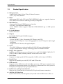
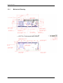
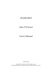
1.3.1
Mechanical Drawing
ROBO-8914VG2AR User’s Manual
1-6
System Overview
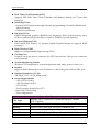
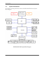
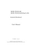
1.4
System Architecture
All of details operating relations are shown in ROBO-8914VG2AR series System
Block Diagram.
ROBO-8914VG2AR System Block Diagram
ROBO-8914VG2AR User’s Manual
1-7
Hardware Configuration
Chapter 2
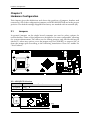
Hardware Configuration
This chapter gives the definitions and shows the positions of jumpers, headers and
connectors. All of the configuration jumpers on ROBO-8914VG2AR are in the proper
position. The default settings shipped from factory are marked with an asterisk ().
2.1
Jumpers
In general, jumpers on the single board computer are used to select options for
certain features. Some of the jumpers are designed to be user-configurable, allowing
for system enhancement. The others are for testing purpose only and should not be
altered. To select any option, cover the jumper cap over (SHORT) or remove (NC) it
from the jumper pins according to the following instructions. Here NC stands for
“Not Connect”.
JP1: ADD2/PGE Selection
JP1
1-2 Short
2-3 Short
Function
PEG ADD2
ROBO-8914VG2AR User’s Manual
2-1
Hardware Configuration
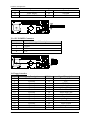
JP2: COM2 Interface Selection
JP2
5-6, 9-11, 10-12, 15-17, 16-18 Short
3-4, 7-9, 8-10, 13-15, 14-16, 21-22 Short
1-2, 7-9, 8-10, 19-20 Short
Function
RS-232 RS-422
RS-485
#1
JP3: CMOS Clear
JP3
1-2 Short
2-3 Short
Function
Normal Operation Clear CMOS Contents
#1
JP4: ME Selection
JP4
Short
Open
Function
Disable
Enable ROBO-8914VG2AR User’s Manual
2-2
Hardware Configuration
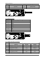
JP5: PCI-E X1,X4 Interface Selection
JP5
Function
Short (1-2, 3-4) PCI-E X4 (Support one slot)
Open
PCI-E X1 (Support four slot) JP6: WDT ,ATX emulation AT mode Selection
JP5
Short (1-2 )
Open (1-2 )
Short (3-4 )
Open (3-4 )
Function
WDT Enable
WDT Disable ATX emulation AT Enable
ATX emulation AT Enable ROBO-8914VG2AR User’s Manual
2-3
Hardware Configuration
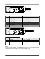
2.2
Connectors
I/O peripheral devices and Flash disk will be connected to these interface connectors
Connector
J1
J2
J3
J4
J5
J6
J7J8/J10/J13
J9
J11
J12
J14
J15
J16/J20
J17
J18/J19/J21/J22
J23
J24
J25/J30/J31
J26
J27
J28
J29
Function
SMBUS Connector
FAN 1 (CPU FAN) Power Connector
FAN 2 (SYSTEN FAN) Power Connector
Parallel Port Connector
+12V Power Connector
CASEOPEN#
DDR3 SLOT
Floppy Connector
COM1 Serial Port 1 Connector
COM2 Serial Port 2 Connector
External PS/2 Keyboard/Mouse Connector
General Purpose I/O Connector
Internal USB Connector
Front Panel Pin HDR
SATA Connector
Ethernet RJ-45 Connector (LAN 1)82567LM
Ethernet RJ-45 Connector (LAN 2) 82574L
External USB Connector
IrDA Connector
TPM Connector
VGA D-SUB Connector
Audio Connector
Remark
5x1 pin header
Connect to CPU
Reserved
6x1 pin header
Reserved
J1: SMBUS Connector
PIN No.
1
2
3
4
5
Signal Description
SMB_CLK
N/C
Ground
SMB_DAT
+5V
#1
ROBO-8914VG2AR User’s Manual
2-4
Hardware Configuration
J2: CPU Fan Connector
PIN No.
1
2
3
4
Signal Description
Ground
+12V
Fan on/off output
Fan Speed control
#1
J3: System Fan Connector
PIN No.
1
2
3
Signal Description
Ground
Fan speed control
Fan on/off output
#1
J4: Parallel Port Connector
PIN No.
1
2
3
4
5
6
7
8
9
10
Signal Description
Strobe#
Data0
Data1
Data2
Data3
Data4
Data5
Data6
Data7
Acknowledge#
ROBO-8914VG2AR User’s Manual
PIN No.
14
15
16
17
18
19
20
21
22
23
Signal Description
Auto Form Feed#
Error#
Initialization#
Printer Select IN#
Ground
Ground
Ground
Ground
Ground
Ground
2-5
Hardware Configuration
11
12
13
Busy
Paper Empty
Printer Select
24
25
26
Ground
Ground
NC
J5: +12V POWER Connector
PIN No.
1
2
3
4
Signal Description
Ground
Ground
+12V
+12V
J9: Floppy Interface
PIN No.
1
3
5
7
9
11
13
15
17
19
21
23
25
27
Signal Description
Ground
Ground
Ground
Ground
Ground
Ground
Ground
Ground
Ground
Ground
Ground
Ground
Ground
Ground
ROBO-8914VG2AR User’s Manual
PIN No.
2
4
6
8
10
12
14
16
18
20
22
24
26
28
Signal Description
Density Select
N/C
DRVEN1
Index#
Motor ENA#
Drive Select B#
Drive Select A#
Motor ENB#
Direction#
Step#
Write Data#
Write Gate#
Track 0#
Write Protect#
2-6
Hardware Configuration
29
31
33
Ground
Ground
Ground
30
32
34
Read Data#
Head Select#
Disk Change#
J11: COM1 Serial Port
PIN No.
1
2
3
4
5
6
7
8
9
10
Signal Description
DCD
DSR
RXD
RTS
TXD
CTS
DTR
RI
Ground
N/C
J12 : COM2 Serial Port 2 Connector
PIN No.
1
2
3
4
5
6
7
Signal Description
RS-232
RS-422
DCD (Data Carrier Detect)
TXN/C
DSR (Data Set Ready)
RXD (Receive Data)
TX+
RTS (Request to Send)
N/C
TXD (Transmit Data)
RX+
CTS (Clear to Send)
N/C
DTR (Data Terminal Ready)
RX-
ROBO-8914VG2AR User’s Manual
RS-485
DATAN/C
DATA+
N/C
N/C
N/C
N/C
2-7
Hardware Configuration
8
9
10
RI (Ring Indicator)
GND (Ground)
N/C
N/C
GND
N/C
N/C
GND
N/C
Note:
J12 (COM2) could be configurable as RS-232/422/485 with jumper JP2.
J14: External PS/2 Keyboard/Mouse Connector
PIN No.
1
3
5
7
9
Signal Description
Mouse Data
N/C
Ground
PS2 Power
Mouse Clock
PIN No.
2
4
6
8
10
Signal Description
Keyboard Data
N/C
Ground
PS2 Power
Keyboard Clock
J15: General Purpose I/O Connector
PIN No.
Signal Description
1
GPIO0
3
5
7
9
GPIO1
GPIO2
GPIO3
Ground
PIN No.
Signal Description
2
GPIO4
4
6
8
10
GPIO5
GPIO6
GPIO7
+5V
Note:
All General Purpose I/O ports can only apply to standard TTL ± 5% signal level
(0V/5V), and each Fan.
ROBO-8914VG2AR User’s Manual
2-8
Hardware Configuration
J17: Front Panel Pin HDR
PIN No.
1
3
5
7
9
11
13
15
Signal Description
PWR_LED(+)
PWR_LED(-)
LAN1_ACT
LAN1_LINK
LAN2_LINK
LAN2_ACT
HDD_LED(+)
HDD_LED(-)
PIN No.
2
4
6
8
10
12
14
16
Signal Description
Speaker(+)
N/C
N/C
Speaker(-)
NC
NC
NC
NC
PIN No.
2
4
6
8
10
Signal Description
5V Dual
USBUSB+
Ground
N/C
J25/J30/J31: External USB Connector
PIN No.
1
3
5
7
Signal Description
5V Dual
USBUSB+
Ground
Key( no pin )
Note:
5V Dual is always available. It's supplied by either 5V VCC power source in normal
operation mode or 5V standby power source in standby mode.
ROBO-8914VG2AR User’s Manual
2-9
Hardware Configuration
J26: IrDA Connector
PIN No.
1
2
3
4
5
6
Signal Description
+5V
N/C
IRRX
IRTX
Ground
N/C
#1
J29: Audio MIC/Line-in/Line-out Connector
PIN No.
1
3
5
7
9
Signal Description
MIC with Reference Voltage
Line-in Left Channel
Line-in Right Channel
Line-out Left Channel
Line-out Right Channel
PIN No.
2
4
6
8
10
#1
ROBO-8914VG2AR User’s Manual
Signal Description
Analog Ground
Analog Ground
Analog Ground
Analog Ground
N/C
#2
2-10
System Installation
Chapter 3
System Installation
This chapter provides you with instructions to set up your system. The additional
information is enclosed to help you set up onboard PCI device and handle Watch
Dog Timer (WDT) and operation of GPIO in software programming.
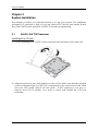
3.1
Intel® LGA 775 Processor
Installing LGA 775 CPU
1) Lift the handling lever of CPU socket outwards and upwards to the other end.
2) Align the processor pins with pinholes on the socket. Make sure that the notched
corner or dot mark (pin 1) of the CPU corresponds to the socket’s bevel end. Then
press the CPU gently until it fits into place . If this operation is not easy or
smooth, don’t do it forcibly. You need to check and rebuild the CPU pin
uniformly.
ROBO-8914VG2AR User’s Manual
3-1
System Installation
Note:
Don’t touch directly by your hand or impacts internal align balls of CPU socket to
avoid motherboard destruction, it is a precise actuator.
3) Push down the lever to lock processor chip into the socket once CPU fits.
4) Follow the installation guide of cooling fan or heat sink to mount it on CPU
surface and lock it on the LGA 775 socket.
Removing CPU
1) Unlock the cooling fan first.
2) Lift the lever of CPU socket outwards and upwards to the other end.
3) Carefully lifts up the existing CPU to remove it from the socket.
4) Follow the steps of installing a CPU to change to another one or place handling
bar to close the opened socket.
ROBO-8914VG2AR User’s Manual
3-2
System Installation
Configuring System Bus
ROBO-8914VG2AR will automatically detect the CPU FSB 800/1066/1333 MHz
used. CPU speed of Intel Core 2 Duo and Intel Core 2 Quad Processor can be
detected automatically.
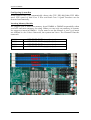
Inserting Memory Module
We suggest you to insert the memory from DIMM0 to DIMM3 sequentially when
you have one more memory for using. When you use only one memory in system,
we suggest to insert in DIMM 0. If you want to use the channel A- slot 2, you must
use channel A- slot 1 first. Otherwise, the system can’t boot. The Channel B has the
same rule.
DIMM3
DIMM2
DIMM1
DIMM0
non-ECC
non-ECC
non-ECC
non-ECC
DDR3
DDR3
DDR3
DDR3
ROBO-8914VG2AR User’s Manual
DIMM channel B - slot 2
DIMM channel B - slot 1
DIMM channel A - slot 2
DIMM channel A - slot 1
3-3
System Installation
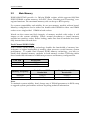
3.2
Main Memory
ROBO-8914VG2AR provide 4 x 240-pin DIMM sockets which supports 800/1066
DDR3 SDRAM as main memory, Non-ECC (Error Checking and Correcting), nonregister functions. The maximum memory size can be up to 8GB capacity.
For system compatibility and stability, do not use memory module without brand.
Memory configuration can be either one double-sided DIMM in either one DIMM
socket or two single-sided DIMM in both sockets.
Watch out the contact and lock integrity of memory module with socket, it will
impact on the system reliability. Follow normal procedures to install memory
module into memory socket. Before locking, make sure that all modules have been
fully inserted into the card slots.
Dual Channel DDR3 DIMM
Dual Channel DDR3 memory technology doubles the bandwidth of memory bus.
Adequate or higher bandwidth of memory than processor would increase system
performance. To enable Dual Channel DDR3 memory technology, you have to
install dual identical memory modules in both memory sockets. Following tables
show bandwidth information of different processor and memory configurations.
CPU FSB
1066MHz
800MHz
Bandwidth
8.5GB/s
6.4GB/s
Memory Frequency
1066MHz
800MHz
Dual Channel DDR
Bandwidth
17GB/s
12.8GB/s
Single Channel DDR
Bandwidth
8.5GB/s
6.4GB/s
Note:
To maintain system stability, don’t change any of DRAM parameters in BIOS setup
to upgrade system performance without acquiring technical information.
ROBO-8914VG2AR User’s Manual
3-4
System Installation
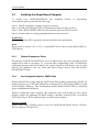
3.3
Installing the Single Board Computer
To install your ROBO-8914VG2AR into
environment, please perform the following:
standard
chassis
or
proprietary
Step 1 : Check all jumpers setting on proper position
Step 2 : Install and configure CPU and memory module on right position
Step 3 : Place ROBO-8914VG2AR into the dedicated position in the system
Step 4 : Attach cables to existing peripheral devices and secure it
WARNING
Please ensure that SBC is properly inserted and fixed by mechanism.
Note:
Please refer to section 3.3.1 to 3.3.7 to install INF/VGA/LAN/Audio/Raid/AMT &
TPM drivers.
3.3.1
Chipset Component Driver
The chipset on ROBO-8914VG2AR is a new chipset that a few old operating systems
might not be able to recognize. To overcome this compatibility issue, for Windows
Operating Systems such as Windows XP, please install its INF before any of other
Drivers are installed. You can select the Intel Chipset driver from the ROBO8914VG2AR CD-title.
3.3.2
Intel Integrated Graphics GMCH Chip
ROBO-8914VG2AR comes with the Intel® GMA 4500 graphics supporting DVMT 5.0
display memory up to 287 MB. Shared 32 accompany it to 1GB system Memory with
Total Graphics Memory. This combination makes ROBO-8914VG2AR an excellent
piece of multimedia hardware.
With no additional video adaptor, this onboard video will usually be the system
display output. By adjusting the BIOS setting to disable on-board VGA, an add-on
PCI-Express by 16 VGA card can take over the system display.
Drivers Support
Please select Intel Graphic driver from the ROBO-8914VG2AR Driver CD-title.
Driver supports Windows XP.
ROBO-8914VG2AR User’s Manual
3-5
System Installation
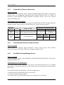
3.3.3
On-board Fast Ethernet Controllers
Drivers Support
Please select Intel Ethernet driver from the ROBO-8914VG2AR Driver CD-title to
install those two integrated Intel® 82567LM Gigabit Ethernet PHY for iAMT 5.0
function & Intel® 82574L Gigabit Ethernet controller drivers. Those two drivers
support Windows XP.
LED Indicator (for LAN status)
This provides two LED indicators to report Intel 82567LM & 82574L Gigabit Ethernet
interface status. Please refer to the table below as a quick reference guide.
82567LM
&82574L
Color
Name of LED
Status
LED
Orange
LAN Linked & Active LED
Speed
LED
3.3.4
Orange
LAN speed LED
Green
Operation of Ethernet Port
Linked
Active
On
Blinking
Giga
Mbps
100
Mbps
10 Mbps
Orange
Green
Off
On-board High Definition Audio Controller
Drivers Support
Please select the Realtek High Definition Codec Audio driver form ROBO8914VG2AR Driver CD-title. The driver supports Windows XP.
3.3.5
Intel Matrix Storage Manager Device
Drivers Support
Please find utility tool for Intel ICH10DO of ROBO-8914VG2AR CD-title. The drivers
support Windows XP.
Installing Serial ATA hard disks
The ROBO-8914VG2AR supports Four Serial ATA hard disk drives. For optimal
performance, install identical drives of the same model and capacity when creating a
disk array.
To install the SATA hard disks for a RAID configuration:
1. Install the SATA hard disks into the drive bays.
2. Connect the SATA signal cables.
3. Connect a SATA power cable to the power connector on each drive.
ROBO-8914VG2AR User’s Manual
3-6
System Installation
Intel RAID configurations
This ROBO-8914VG2AR supports RAID 0, RAID 1, RAID 5, RAID (1+0) and Intel®
Matrix Storage configurations for Serial ATA hard disks drives through the Intel
ICH10DO Southbridge chip.
RAID configurations
RAID 0 (Data striping) optimizes two identical hard disk drives to read and write
data in parallel, interleaved stacks. Two hard disks perform the same work as a
single drive but at a sustained data transfer rate, double that of a single disk alone,
thus improving data access and storage. Use of two new identical hard disk drives is
required for this setup.
RAID 1 (Data mirroring) copies and maintains an identical image of data from one
drive to a second drive. If one drive fails, the disk array management software
directs all applications to the surviving drive as it contains a complete copy of the
data in the other drive. This RAID configuration provides data protection and
increases fault tolerance to the entire system. Use two new drives or use an existing
drive and a new drive for this setup. The new drive must be of the same size or
larger than the existing drive.
RAID 5 stripes both data and parity information across three or more hard disk
drives. Among the advantages of RAID 5 configuration include better HDD
performance, fault tolerance, and higher storage capacity. The RAID 5 configuration
is best suited for transaction processing, relational database applications, enterprise
resource planning, and other business systems. Use a minimum of three identical
hard disk drives for this setup.
RAID 10 is data striping and data mirroring combined without parity (redundancy
data) having to be calculated and written. With the RAID 10 configuration you get
all the benefits of both RAID 0 and RAID 1 configurations. Use four new hard disk
drives or use an existing drive and three new drives for this setup.
Intel Matrix Storage Manager. The Intel® Matrix Storage technology supported by
the ICH10DO chip allows you to create a RAID 0 and a RAID 1 set using only two
identical hard disk drives. The Intel® Matrix Storage technology creates two
partitions on each hard disk drive to create a virtual RAID 0 and RAID 1 sets. This
technology also allows you to change the hard disk drive partition size without
losing any data.
ROBO-8914VG2AR User’s Manual
3-7
System Installation
3.3.6
AMT Function Installation
A major barrier to greater IT efficiency has been removed by Intel® Active
Management Technology (Intel® AMT) a feature on Intel® vPro™ technology.
Using built-in platform capabilities and popular third-party management and
security applications, Intel AMT allows IT to better Discover, Heal, and protects
their networked computing assets.
Drivers Support
Installing ME (Management Engine) Drivers (which includes HECI Driver and
LMS_SOL Driver) and operating PCI serial port and PCI simple communications
controller. Driver supports Windows XP.
3.3.7
Intel Trusted Platform Module
The Trusted Platform Module (TPM) can securely store keys, digital certificates,
passwords and data.
Drivers Support
Please select the TPM Driver form ROBO-8914VG2AR Driver CD-title. Driver
supports Windows XP.
3.4
Clear CMOS Operation
The following table indicates how to enable/disable Clear CMOS Function hardware
circuit by putting jumpers at proper position.
JP3: CMOS Clear
JP3
1-2 Short
2-3 Short
Function
Normal Operation Clear CMOS Contents
ROBO-8914VG2AR User’s Manual
3-8
System Installation
3.5
WDT Function
The working algorithm of the WDT function can be simply described as a counting
process. The Time-Out Interval can be set through software programming. The
availability of the time-out interval settings by software or hardware varies from
boards to boards.
ROBO-8914VG2AR allows users control WDT through dynamic software
programming. The WDT starts counting when it is activated. It sends out a signal to
system reset or to non-maskable interrupt (NMI), when time-out interval ends. To
prevent the time-out interval from running out, a re-trigger signal will need to be
sent before the counting reaches its end. This action will restart the counting process.
A well-written WDT program should keep the counting process running under
normal condition. WDT should never generate a system reset or NMI signal unless
the system runs into troubles.
The related Control Registers of WDT are all included in the following sample
program that is written in C language. User can fill a non-zero value into the Timeout Value Register to enable/refresh WDT. System will be reset after the Time-out
Value to be counted down to zero. Or user can directly fill a zero value into Timeout Value Register to disable WDT immediately. To ensure a successful accessing to
the content of desired Control Register, the sequence of following program codes
should be step-by-step run again when each register is accessed.
Additionally, there are maximum 2 seconds of counting tolerance that should be
considered into user’ application program. For more information about WDT, please
refer to Winbond W83627THG data sheet.
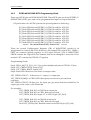
There are two PNP I/O port addresses that can be used to configure WDT,
1) 0x2E:EFIR (Extended Function Index Register, for identifying CR index number)
2) 0x2F:EFDR (Extended Function Data Register, for accessing desired CR)
Below are some example codes, which demonstrate the use of WDT.
//Step1. Enter W83627THG configuration registers mode:
outportb(0x2E, 0x87);
outportb(0x2E, 0x87);
//* Step2. Pin89 to be WDTO
outportb(0x2E, 0x2b);
outportb(0x2E + 1, 0x04);
//* Step3. Select logic device 8:
outportb(0x2E, 0x07);
outportb(0x2E + 1, 0x08);
ROBO-8914VG2AR User’s Manual
3-9
System Installation
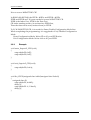
//* Step4. Config WDT using second to be unit:
outportb(0x2E, 0xf5);
outportb(0x2E + 1, 0x00);
//* Step5. Set WDT time-out time:
outportb(0x2E, 0xf6);
outportb(0x2E + 1, time_out);
//* Step6. Exit configuration registers mode:
outportb(0x2E, 0xaa);
3.6
GPIO
The ROBO-8914VG2AR provides 8 programmable input or output ports that can be
individually configured to perform a simple basic I/O function. Users can configure
each individual port to become an input or output port by programming register bit
of I/O Selection. To invert port value, the setting of Inversion Register has to be
made. Port values can be set to read or write through Data Register.
3.6.1
Pin assignment
J15 : General Purpose I/O Connector
PIN No.
1
2
3
4
5
6
7
8
9
10
Signal Description
General Purpose I/O Port 0 (GPIO0)
General Purpose I/O Port 4 (GPIO4)
General Purpose I/O Port 1 (GPIO1)
General Purpose I/O Port 5 (GPIO5)
General Purpose I/O Port 2 (GPIO2)
General Purpose I/O Port 6 (GPIO6)
General Purpose I/O Port 3 (GPIO3)
General Purpose I/O Port 7 (GPIO7)
Ground
+5V
All General Purpose I/O ports can only apply to standard TTL ± 5% signal level
(0V/5V), and each source sink capacity up to 12mA.
ROBO-8914VG2AR User’s Manual
3-10
System Installation
3.6.2
ROBO-8914VG2AR GPIO Programming Guide
There are 8 GPIO pins on ROBO-8914VG2AR. These GPIO pins are from SUPER I/O
(W83627THG) GPIO pins, and can be programmed as Input or Output direction.
J15 pin header is for 8 GPIO pins and its pin assignment as following :
J15_Pin1=GPIO0:from SUPER I/O_GPIO10 with Ext. 4.7K PH
J15_Pin2=GPIO4:from SUPER I/O_GPIO14 with Ext. 4.7K PH
J15_Pin3=GPIO1:from SUPER I/O_GPIO11 with Ext. 4.7K PH
J15_Pin4=GPIO5:from SUPER I/O_GPIO15 with Ext. 4.7K PH
J15_Pin5=GPIO2:from SUPER I/O_GPIO12 with Ext. 4.7K PH
J15_Pin6=GPIO6:from SUPER I/O_GPIO16 with Ext. 4.7K PH
J15_Pin7=GPIO3:from SUPER I/O_GPIO13 with Ext. 4.7K PH
J15_Pin8=GPIO7:from SUPER I/O_GPIO17 with Ext. 4.7K PH
<<<<< Be careful Pin9=GND , Pin10=VCC >>>>>
There are several Configuration Registers (CR) of W83627THG needed to be
programmed to control the GPIO direction, and status(GPI)/value(GPO). CR00h ~
CR2F are common (global) registers to all Logical Devices (LD) in W83627THG.
CR07h contains the Logical Device Number that can be changed to access the LD as
needed. LD7 contains the GPIO10~17 registers.
Programming Guide:
Step1: CR2A_Bit [7.2]. P [1,1,1,1,1,1]; to select multiplexed pins as GPIO10~17 pins
Step2: LD7_CR07h.P [07h]; Point to LD7
Step3: LD7_CR30h_Bit0.P1; Enable LD7
Step4: Select GPIO direction, Get Status or output value.
LD7_CRF0h; GPIO17 ~ 10 direction, 1 = input, 0 = output pin
LD7_CRF2h.P [00h]; Let CRF1 (GPIO data port) non-invert to prevent from
confusion
LD7_CRF1h; GPIO17~10 data port, for input pin, get status from the related bit, for
output pin, write value to the related bit.
For example,
LD7_CRF0h_Bit4.P0; Let GPIO14 as output pin
LD7_CRF2h_Bit4.P0; Let CRF1_Bit4 non-inverted
LD7_CRF1h_Bit4.P0; Output “0” to GPIO14 pin (J15_Pin2)
LD7_CRF0h_Bit0.P1; Let GPIO10 as input pin
LD7_CRF2h_Bit0.P0; Let CRF1_Bit0 non-inverted
Read LD7_CRF1h_Bit0; Read the status from GPIO10 pin (J15_Pin1)
ROBO-8914VG2AR User’s Manual
3-11
System Installation
How to access W83627THG CR?
In ROBO-8914VG2AR, the EFER = 002Eh, and EFDR = 002Fh.
EFER and EFDR are 2 IO ports needed to access W83627THG CR.
EFER is the Index Port, EFDR is the Data Port.
CR index number needs to be written into EFER first,
Then the data will be read/written from/to EFDR.
To R/W W83627THG CR, it is needed to Enter/Enable Configuration Mode first.
When completing the programming, it is suggested to Exit/Disable Configuration
Mode.
Enter Configuration Mode: Write 87h to IO port EFER twice.
Exit Configuration Mode: Write AAh to IO port EFER.
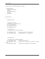
3.6.3
Example
void enter_Superio2_CFG(void)
{
outportb(0x2E, 0x87);
outportb(0x2E, 0x87);
}
void exit_Superio2_CFG(void)
{
outportb(0x2E, 0xAA);
}
void Set_CFG2(unsigned char Addr2,unsigned char Value2)
{
unsigned char d2;
outportb(0x2E, Addr2);
delay(2);
outportb(0x2E +1, Value2);
delay(2);
}
ROBO-8914VG2AR User’s Manual
3-12
System Installation
unsigned char Get_CFG2(unsigned char Addr2)
{
unsigned char d2;
outportb(0x2E, Addr2);
delay(2);
d2 = inportb(0x2E +1);
delay(2);
return(d2);
}
int main(void)
{
unsigned char d2;
enter_Superio2_CFG();
/* CR2A B7 = 1 selet GPIO Port 1*/
d2 = Get_CFG2(0x2A);
d2 = (d2 & 0x7F) | 0x80;
Set_CFG2(0x2A, d2);
/* IO test loop 1 */
/* Set GPIO Port 1 of Superio 2 Enable */
Set_CFG2(0x07, 0x07);
Set_CFG2(0x30, 0x01);
/* Select logic device 07 of Superio2*/
/* Enable GPIO Port 1 of Superio2*/
/* IO test loop 1 */
/* Set GPIO Port 1 of Superio2 Enable */
Set_CFG2(0x07, 0x07);
/* Select logic device 07*/
Set_CFG2(0xF0, 0x0F);
/* GPIO Port 1 of Superio2 is [ooooiiii], o: output,
i:input */
Set_CFG2(0xF2, 0x00);
/* GPIO Port 1 of Superio2 is non-inversed*/
ROBO-8914VG2AR User’s Manual
3-13
System Installation
Set_CFG2(0x07, 0x07);
Set_CFG2(0xF1, 0xFF);
/* Select logic device 07*/
/* Initial back all GPIO Port1 of Superio 2 to hi */
Set_CFG2(0x07, 0x07);
Set_CFG2(0xF1, 0xEF);
Set_CFG2(0x07, 0x07);
d2 = Get_CFG2(0xF1);
/* Select logic device 07*/
/* GP14 of Superio2 -> ~GP10 of Superio2 */
/* Select logic device 07 of Superio2*/
/* get GPIO Port 2 data */
if (d2 == 0xEE )
printf("\n GPIO14->10 test ok");
else
printf("\n GPIO14->10 test fail ");
ROBO-8914VG2AR User’s Manual
3-14
BIOS Setup Information
Chapter 4
BIOS Setup Information
ROBO-8914VG2AR is equipped with the AMI BIOS stored in Flash ROM. These
BIOS has a built-in Setup program that allows users to modify the basic system
configuration easily. This type of information is stored in CMOS RAM so that it is
retained during power-off periods. When system is turned on, ROBO-8914VG2AR
communicates with peripheral devices and checks its hardware resources against the
configuration information stored in the CMOS memory. If any error is detected, or
the CMOS parameters need to be initially defined, the diagnostic program will
prompt the user to enter the SETUP program. Some errors are significant enough to
abort the start up
4.1
Entering Setup -- Launch System Setup
Power on the computer and the system will start POST (Power On Self Test) process.
When the message below appears on the screen, press <Del> key to enter Setup.
Press <Del> to enter SETUP
If the message disappears before you respond and you still wish to enter Setup,
restart the system by turning it OFF and On or pressing the RESET button. You may
also restart the system by simultaneously pressing <Ctrl>, <Alt>, and <Delete> keys.
Press <F1> to Run SETUP or Resume
The BIOS setup program provides a General Help screen. You can call up this screen
from any menu by simply pressing <F1>. The Help screen lists the appropriate keys
to use and the possible selections for the highlighted item. Press <Esc> to exit the
Help screen.
ROBO-8914VG2AR User’s Manual
4-1
BIOS Setup Information
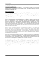
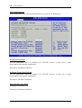
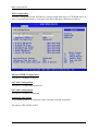
4.2
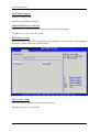
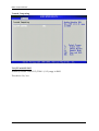
Main Menu
Use this menu for basic system configurations, such as time, date etc.
Standard BIOS Features
AMI BIOS, Processor, System Memory
These items show the firmware and hardware specifications of your system. Read
only.
System Time
The time format is <Hour> <Minute> <Second>. Use [+] or [-] to configure system
Time.
System Date
The date format is <Day>, <Month> <Date> <Year>. Use [+] or [-] to configure
system Date.
ROBO-8914VG2AR User’s Manual
4-2
BIOS Setup Information
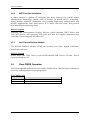
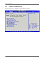
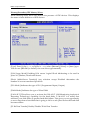
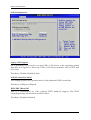
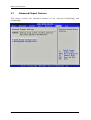
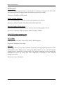
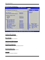
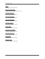
4.3
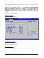
Advanced BIOS Features
Use this menu to set up the items of special enhanced features.
ROBO-8914VG2AR User’s Manual
4-3
BIOS Setup Information
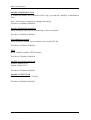
CPU Configuration
These items show the advanced specifications of your CPU. Read only.
Hardware Prefetcher
For UP platforms, leave it enabled. For DP/MP servers, it may use to tune
performance the specific application.
The choice: Disabled, Enabled.
Adjacent Cache Line Prefetch
For UP platforms, leave it enabled. For DP/MP servers, it may use to tune
performance the specific application.
The choice: Disabled, Enabled.
Max CPUID Value Limit
Disabled for Windows XP
The choice: Disabled, Enabled.
ROBO-8914VG2AR User’s Manual
4-4
BIOS Setup Information
Intel(R) Virtualization Tech
A VMM can utilize the additional HW Caps, provided by Intel(R) Virtualization
Tech.
Note: A full reset is required to change the setting.
The choice: Disabled, Enabled.
Execute-Disable Bit capability
When disabled, force the XD feature flag to always return 0
The choice: Disabled, Enabled.
Core Multi-Processing
When disabled, disable one execution core of each CPU die.
The choice: Disabled, Enabled.
PECI
When enabled, enables PECI interface.
The choice: Disabled, Enabled.
Intel(R) Speed Step (tm) Tech
Disable: Disable GV3.
Enable: Enable GV3.
The choice: Disabled, Enabled.
Intel(R) C-STATE Tech
CPU idle is set to C2, C3, C4 State.
The choice: Disabled, Enabled.
ROBO-8914VG2AR User’s Manual
4-5
BIOS Setup Information
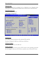
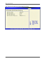
IDE Configuration
The IDE Configuration the IDE devices, such as hard disk drive or CD-ROM drive. It
uses a separate sub menu to configure each hard disk drive (Master and Slave).
Mirrored IDER Configuration
The choice: Disabled, Enabled.
SATA#1 Configuration
The choice: Compatible, Enhanced.
SATA#2 Configuration
The choice: Disabled, Enhanced
Configure SATA#1 as
This setting specifies the function of the on-chip SATA#1 controller.
The choice: IDE, RAID, AHCI.
ROBO-8914VG2AR User’s Manual
4-6
BIOS Setup Information
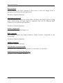
Primary/Secondary IDE Master / Slave
While entering setup, BIOS auto detects the presence of IDE devices. This displays
the status of auto detection of IDE devices.
[Type] Press PgUp/<+> or PgDn/<-> to select [Manual], [None] or [Auto] type.
You can use [Manual] to define your own drive type manually.
[LBA/Large Mode] Enabling LBA causes Logical Block Addressing to be used in
place of Cylinders, Heads and Sectors.
[Block (Multi-Sector Transfer)] Any selection except Disabled determines the
number of sectors transferred per block.
[PIO Mode] Indicates the type of PIO (Programmed Input/Output)
[DMA Mode] Indicates the type of Ultra DMA
[S.M.A.R.T.] This allows you to activate the S.M.A.R.T. (Self-Monitoring Analysis &
Reporting Technology) capability for the hard disks. S. M.A.R.T is a utility that
monitors your disk status to predict hard disk failure. This gives you an opportunity
to move data from a hard disk that is going to fail to a safe place before the hard disk
becomes offline.
[32 Bit Data Transfer] Enable/Disable 32-bit Data Transfer.
ROBO-8914VG2AR User’s Manual
4-7
BIOS Setup Information
Hard Disk Write Protect
Disabled/Enabled device write protection, this will be effective only if device is
accessed through BIOS.
The choice: Disabled, Enabled.
IDE Detect Time Out (Sec)
Select the time out value for detecting ATA/ATAPI device (s).
The choice: 0, 5, 10, 15, 20, 25, 30, 35.
ATA(PI) 80Pin Cable Detection
Select the mechanism for detecting 80Pin ATA (PI) cable.
The choice: Host & Device, Host, Device.
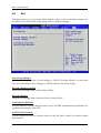
Floppy Configuration
This Sub-Menu contains Setup Items which control configuration of the Internal
Graphics Display Device.
ROBO-8914VG2AR User’s Manual
4-8
BIOS Setup Information
Floppy A
Select the type of floppy drive connected to the system.
The choice: None, 360KB 5 1/4”, 1.2MB 5 1/4”, 720KB 3 1/2”, 1.44MB 3 1/2”,
2.88MB 3 1/2”.
Super IO Configuration
Configure Win627DHG Super IO Chipset.
OnBoard Floppy Controller
This item allows enable/disable onboard Floppy disk controller.
The choice: Disabled, Enabled.
Serial Port 1 Address
Allows BIOS to Select Serial Port1 Base Addresses.
The choice: Disabled, 3F8/IRQ4, 3E8/IRQ4
Serial Port 2 Address
Allows BIOS to Select Serial Port2 Base Addresses.
The choice: Disabled, 2F8/IRQ3, 2E8/IRQ3.
ROBO-8914VG2AR User’s Manual
4-9
BIOS Setup Information
Serial Port 2 Mode
This item allows users to select Infrared transmission mode.
The choice: Normal, IrDA, ASK IR.
Parallel Port Address
This item allows you to configuring I/O of the onboard parallel port.
The choice: Disabled, 378, 278, 3BC.
Parallel Port Mode
There are five different modes for the onboard parallel port:
Watch Dog Timer set
This BIOS testing option is able to reset the system according to the selected table.
The Choice: Disabled, 30, 60, 90, 120, 150, 180, 210 sec.
ROBO-8914VG2AR User’s Manual
4-10
BIOS Setup Information
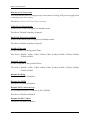
Hardware Health Configure
Configuration / Monitor the Hardware Health. Read only.
ACPI Configuration
ROBO-8914VG2AR User’s Manual
4-11
BIOS Setup Information
AHCI Settings
General ACPI Configuration
ROBO-8914VG2AR User’s Manual
4-12
BIOS Setup Information
Suspend mode
This item specifies the power saving modes for ACPI function. If your operating
system supports ACPI, you can choose to enter the Standby mode in S1 (POS) or S3
(STR) fashion through the setting of this field. Options are:
[S1 (POS)] The S1 sleep mode is a low power state. In this state, no system context is
lost (CPU or chipset) and hardware maintains all system contexts.
[S3 (STR)] The S3 sleep mode is a lower power state where the information of system
configuration and open applications/ files is saved to main memory that remains
powered while most other hardware components turn off to save energy. The
information stored in memory will be used to restore the system when a “wake up”
event occurs.
Repost Video on S3 Resume
Determines whether to invoke VGA BIOS post on S3/STR resume.
The choice: No, Yes
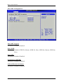
Advanced ACPI Configuration
Advanced ACPI Configuration settings, Use this section to configure additional ACPI
options.
ROBO-8914VG2AR User’s Manual
4-13
BIOS Setup Information
ACPI Version Features
Enable RSDP pointers to 64-bit Fixed System Description Tables.
The choice: ACPI v1.0 / ACPI v2.0 / ACPI v3.0.
ACPI APIC support
Include ACPI APIC table pointer to RSDT pointer list.
The choice: Disabled, Enabled.
AMI OEMB table
Include OEMB table pointer to R(X) SDT pointer list.
The choice: Disabled, Enabled.
Headless mode
Enable / Disable Headless operation mode through ACPI.
The choice: Disabled, Enabled.
South Bridge ACPI Configuration
The South Bridge ACPI related Configuration settings, Use this section to configure
additional ACPI options.
ROBO-8914VG2AR User’s Manual
4-14
BIOS Setup Information
Energy Lake Feature
Select the ACPI state used for System Suspend.
The choice: Disabled, Enabled.
APIC ACPI SCI IRQ
Enable / Disable APIC ACPI SCI IRQ.
The choice: Disabled, Enabled.
USB Device Wakeup From S3/S4
Enable / Disable USB device Wake from S3/S4 mode.
The choice: Disabled, Enabled.
High Performance Event Timer
The choice: Disabled, Enabled.
AHCI Configuration
Select for AHCI Configuration.
ROBO-8914VG2AR User’s Manual
4-15
BIOS Setup Information
AHCI BIOS Support
Enables for supporting
The choice: Disabled, Enabled.
AHCI CD/DVD Boot Time out
Some SATA CD/DVD in AHCI mode need to wait ready longer.
The choice: 0, 5, 10, 15, 20, 25, 30, 35.
AHCI Port0 ~ Port5
While entering setup, BIOS auto detects the presence of IDE devices. This displays
the status of auto detection of IDE devices.
SATA Port0 ~ Port5
Select the type of device connected to the system.
The choice: Auto, Not Installed.
ROBO-8914VG2AR User’s Manual
4-16
BIOS Setup Information
S.M.A.R.T
This allows you to activate the S.M.A.R.T. (Self-Monitoring Analysis & Reporting
Technology) capability for the hard disks. S. M.A.R.T is a utility that monitors your
disk status to predict hard disk failure. This gives you an opportunity to move data
from a hard disk that is going to fail to a safe place before the hard disk becomes
offline.
The choice: Disabled, Enabled.
APM Configuration
Select for APM Configuration.
Power Management/APM
Enables for Power Management.
The choice: Disabled, Enabled.
Power Button Mode
Go into On/Off or Suspend when Power button is pressed.
The choice: On/Off, Suspend.
ROBO-8914VG2AR User’s Manual
4-17
BIOS Setup Information
Restore on AC Power loss
This item allows user to configure the power status of using ATX power supply after
a serious power loss occurs.
The choice: Power Off, Power On, Last state.
Video Power Down Mode
Power Down video in Suspend or Standby mode.
The choice: Disable, Standby, Suspend.
Hard Disk Power Down Mode
Power Down Hard Disk in Suspend or Standby mode.
The choice: Disable, Standby, Suspend.
Standby Time out
Go into Standby in the specified Time.
The choice: Disable. 1 Min, 2 Min, 4 Min, 8 Min, 10 Min, 20 Min, 30 Min, 40 Min,
50 Min, 60 Min.
Suspend Time out
Go into Suspend in the specified Time.
The choice: Disable. 1 Min, 2 Min, 4 Min, 8 Min, 10 Min, 20 Min, 30 Min, 40 Min,
50 Min, 60 Min.
Resume On Ring
The choice: Disabled, Enabled.
Resume On PME#
The choice: Disabled, Enabled.
Resume PCI-E card wake-up
For J24 Ethernet RJ-45 Connector (LAN 2) 82574L
The choice: Disabled, Enabled.
Resume On RTC Alarm
The choice: Disabled, Enabled.
ROBO-8914VG2AR User’s Manual
4-18
BIOS Setup Information
Intel AMT Configuration
Intel AMT Support
The choice: Disabled, Enabled.
Force IDER
The choice: Disabled, IDER Pri. Master, IDER Pri. Slave, IDER Sec. Master, IDER Sec.
Slave
Force SOL
The choice: Disabled, Enabled.
Unconfigure AMT/ME
The choice: Disabled, Enabled.
Activate Remote Assistance
The choice: Disabled, Enabled.
ROBO-8914VG2AR User’s Manual
4-19
BIOS Setup Information
Trusted Computing
TCG/TPM SUPPORT
Enabled/Disable TPM TCG (TPM 1.1/1.2) supp in BIOS.
The choice: No, Yes.
ROBO-8914VG2AR User’s Manual
4-20
BIOS Setup Information
USB Configuration
Legacy USB Support
Set to [Enabled] if you need to use any USB 1.1/2.0 device in the operating system
that does not support or have any USB 1.1/2.0 driver installed, such as DOS and
SCO Unix.
The choice: Disabled, Enabled, Auto.
USB 2.0 Controller Mode
This setting specifies the operation mode of the onboard USB 2.0 controller.
The choice: FullSpeed, HiSpeed.
BIOS EHCI Hand-Off
This is a workaround for OSes without EHCI hand-off support. The EHCI
ownership change should claim by EHCI driver.
The choice: Disabled, Enabled.
ROBO-8914VG2AR User’s Manual
4-21
BIOS Setup Information
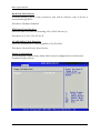
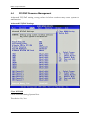
4.4
PCI/PNP Resource Management
Advanced PCI/PnP setting wrong values in below sections may cause system to
malfunction.
Advanced PCI/PnP Settings
Clear NVRAM
Clear NVRAM during System Boot.
The choice: No, Yes.
ROBO-8914VG2AR User’s Manual
4-22
BIOS Setup Information
Plug & Play O/S
No: lets the BIOS configure all the devices in the system.
Yes: lets the operating system configure Plug and Play (PnP) devices not required for
boot if your system has a Plug and Play operating system.
The choice: No, Yes.
PCI Latency Timer
Select value in units of PCI clocks for PCI device latency timer register.
The choice: 32, 64, 96, 128, 160, 192, 224, 248.
Allocate IRQ to PCI VGA
Yes: Assigns IRQ to PCI VGA card if card requests an IRQ.
No: Does not assign IRQ to PCI VGA card even if card requests an IRQ.
The choice: No, Yes.
Palette Snooping
Enabled: informs the PCI devices that an ISA graphics device is installed in the
system so the card will function correctly.
The choice: Disabled, Enabled.
PCI IDE BusMaster
Enabled: Uses PCI bus mastering for reading / writing to IDE drives.
The choice: Disabled, Enabled.
OffBoard PCI/ISA IDE Card
Some PCI IDE cards may require this to be set to the PCI slot number that is holding
the card. AUTO: Works for most PCI IDE cards
The choice: Auto, PCI Slot1, PCI Slot2, PCI Slot3, PCI Slot4, PCI Slot5, PCI Slot6.
IRQ 3 / IRQ 4 / IRQ5 / IRQ7 / IRQ 9 / IRQ 10 / IRQ 11 / IRQ 14 / IRQ 15
Available: Specified IRQ is available to be used by PCI/PnP devices.
Reserved: Specified IRQ is reserved for used by Legacy ISA devices.
The choice: Available, Reserved.
ROBO-8914VG2AR User’s Manual
4-23
BIOS Setup Information
DMA Channel 0 / DMA Channel 1 / DMA Channel 3 / DMA Channel 5 / DMA
Channel 6 / DMA Channel 7
Available: Specified DMA is available to be used by PCI/PnP devices.
Reserved: Specified DMA is reserved for use by Legacy ISA devices.
The choice: Available, Reserved.
Reserved Memory Size
Select Size of memory block to reserve for legacy ISA devices.
The choice: Disabled, 16K, 32K, 64K.
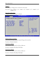
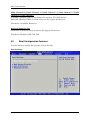
4.5
Boot Configuration Features
Use this menu to specify the priority of boot devices.
Boot Setttings
ROBO-8914VG2AR User’s Manual
4-24
BIOS Setup Information
Boot Setttings Configuration
Quick Boot
Allows BIOS to skip certain tests while booting. This will decrease the time needed
to boot the system.
The choice: Disabled, Enabled.
Quiet Boot
Disabled: Displays normal POST messages.
Enabled: Displays OEM Logo instead of POST messages.
The choice: Disabled, Enabled.
AddOn ROM Display Mode
Set display mode for Option ROM.
This item is used to determine the display mode when an optional ROM is initialized
during POST. When set to [Force BIOS], the display mode used by AMI BIOS is
used. Select [Keep Current] if you want to use the display mode of optional ROM.
The choice: Force BIOS, Keep Current.
ROBO-8914VG2AR User’s Manual
4-25
BIOS Setup Information
Bootup Num-Lock
Select Power-on state for Numlock.
This setting is to set the Num Lock status when the system is powered on.
Setting to [On] will turn on the Num Lock key when the system is powered on.
Setting to [Off] will allow users to use the arrow keys on the numeric keypad.
The choice: Off, On.
PS/2 Mouse support
Select support for PS/2 Mouse.
Select [Enabled] if you need to use a PS/2-interfaced mouse in the operating system.
The choice: Disabled, Enabled, Auto.
Wait For ‘F1’ If Error
When this setting is set to [Enabled] and the boot sequence encounters an error, it
asks you to press F1. If disabled, the system continues to boot without waiting for
you to press any keys.
The choice: Disabled, Enabled.
Hit ‘DEL’ Message Display
Set this option to [Disabled] to prevent the message as follows:
Hit Del if you want to run setup
It will prevent the message from appearing on the first BIOS screen when the
computer boots. Set it to [Enabled] when you want to run the BIOS Setup Utility.
The choice: Disabled, Enabled.
Interrupt 19 Capture
Interrupt 19 is the software interrupt that handles the boot disk function. When
enabled, this BIOS feature allows the ROM BIOS of these host adaptors to "capture"
Interrupt 19 during the boot process so that drives attached to these adaptors can
function as bootable disks. In addition, it allows you to gain access to the host
adaptor's ROM setup utility, if one is available.
When disabled, the ROM BIOS of these host adaptors will not be able to "cap ture"
Interrupt 19. Therefore, you will not be able to boot operating systems from any
bootable disks attached to these host adaptors. Nor will you be able to gain access to
their ROM setup utilities.
The choice: Disabled, Enabled.
ROBO-8914VG2AR User’s Manual
4-26
BIOS Setup Information
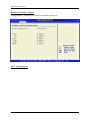
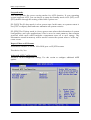
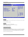
Boot Device Priority
1st Boot Device
The items allow you to set the sequence of boot devices where BIOS attempts to load
the disk operating system. First press <Enter> to enter the sub-menu. Then you may
use the arrow keys (↑↓) to select the desired device, then press <+>, <-> or
<PageUp>, <PageDown> key to move it up/down in the priority list.
The choice: (Network: IBA GE Slot 00C8 v1324), Disabled.
ROBO-8914VG2AR User’s Manual
4-27
BIOS Setup Information
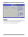
Hard Disk Drives
1st Drive
This setting allows users to set the priority of the removable devices. First press
<Enter> to enter the sub-menu. Then you may use the arrow keys (↑↓) to select the
desired device, then press <+>, <-> or <PageUp>, <PageDown> key to move it
up/down in the priority list.
ROBO-8914VG2AR User’s Manual
4-28
BIOS Setup Information
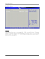
4.6
BIOS Security Features
Use this menu to set supervisor and user passwords.
Security Settings
Install or Change the password.
Supervisor Password / Change Supervisor Password
Supervisor Password controls access to the BIOS Setup utility. These settings allow
you to set or change the supervisor password. Please press “Enter” to key-in.
User Password / Change User Password
User Password controls access to the system at boot. These settings allow you to set
or change the user password.
Boot Sector Virus Protection
Boot Sector Virus Protection.
The choice: Disabled, Enabled.
ROBO-8914VG2AR User’s Manual
4-29
BIOS Setup Information
4.7
Advanced Chipset Features
This menu controls the advanced features of the onboard Northbridge and
Southbridge.
ROBO-8914VG2AR User’s Manual
4-30
BIOS Setup Information
North Bridge Chipset Configuration
Memory Remap Feature
ENABLE: Allow remapping of overlapped PCI memory above the total physical
memory. DISBALE: Do not allow remapping of memory.
The choice: Disabled, Enabled.
PCI MMIO Allocation
4GB To 3072MB. (Read Only)
DRAM Frequency
Users are recommended to use Auto for memory frequency selection.
The choice: Auto, 533, 667, 800, 1067 MHz.
Configure DRAM Timing by SPD
This option provides DRAM plug-and-play support by serial presence detect (SPD)
mechanism via the system management bus (SMBUS) interface.
The choice: Disabled, Enabled.
ROBO-8914VG2AR User’s Manual
4-31
BIOS Setup Information
Memory Hole
In order to improve performance, certain space in memory is reserved for ISA cards.
This memory must be mapped into the memory space below 16MB.
The choice: Disabled, 15MB-16MB.
Initate Graphic Adapter
Select which graphics controller to use as the primary boot device.
The choice: IGD, PCI/IGD, PCI/PEG, PEG/IGD, PEG/PCI.
Internal Graphics Mode Select
Select the amount of system memory used by the internal graphics device.
The choice: Enabled, 32MB, Enabled, 64MB, Enabled, 128MB.
IGD GTT Graphic smemory size
No VT mode, 2MB. (Read Only)
PAVP Mode
GMCH Protected Audio Video Path (PAVP) BIOS Support.
The choice: Disabled, Lite, High.
PEG Port
This setting allows you to select whether to use the on-chip graphics processor or the
PCI Express card. When set to [Auto], the BIOS checks to see if a PCI Express
graphics card is installed. If it detects that a PCI Express graphics card is present, the
motherboard boots up using that card. Otherwise, it defaults to the onboard
graphics processor.
The choice: Auto, Disabled.
ROBO-8914VG2AR User’s Manual
4-32
BIOS Setup Information
Video Function Configuration
DVMT Mode Select
Intel's Dynamic Video Memory Technology (DVMT) allows the system to
dynamically allocate memory resources according to the demands of the system at
any point in time. The key idea in DVMT is to improve the efficiency of the memory
allocated to either system or graphics processor.
It is recommended that you set this BIOS feature to DVMT Mode for maximum
performance. Setting it to DVMT Mode ensures that system memory is dynamically
allocated for optimal balance between graphics and system performance.
The choice: Fixed Mode, DVMT Mode.
DVMT/FIXED Memory
When set to DVMT/FIXED Mode, the graphics driver will allocate a fixed amount of
memory as dedicated graphics memory, as well as allow more system memory to be
dynamically allocated between the graphics processor and the operating system.
The choice: 128MB, 256MB.
ROBO-8914VG2AR User’s Manual
4-33
BIOS Setup Information
Flat Panel Type
The choice: 640x480 18 bit, 800x600 18 bit, 1024x768 18 bit, 1280x1024 18bit,
1400x1050 18 bit, 1600x1200 18bit, 800x600 24 bit, 1024x768 24 bit, 1280x1024 24 bit.
Spread Spectrum Clock
The choice: Disabled, Enabled.
South Bridge Configuration
USB Functions
This setting specifies the function of the onboard USB controller.
The choice: Disabled, 2 USB Ports, 4 USB Ports, 6 USB Ports.
USB Port Configure
The choice: 6x6 USB Ports, 8x4 USB Ports.
USB 2.0 Controller
Set to [Enabled] if you need to use any USB 2.0 device in the operating system that
does not support or have any USB 2.0 driver installed, such as DOS and SCO Unix.
ROBO-8914VG2AR User’s Manual
4-34
BIOS Setup Information
GbE LAN Boot
When [Enabled], the BIOS attempts to boot from a LAN boot image before it
attempts to boot from a local storage device.
The choice: Enabled, Disabled.
GbE Wake Up From S5
This field specifies whether the system will be awakened from the S5 power saving
mode when activity or input signal of onboard LAN For J23 Ethernet RJ-45
Connector (LAN 1)82567LM is detected.
The choice: Enabled, Disabled.
GPI09 Configuration
The choice: WOL Enabled, High, Low.
HDA Controller
This setting controls the High Definition Audio interface integrated in the
Southbridge.
The choice: Enabled, Disabled.
SMBUS Controller
The choice: Enabled, Disabled.
SLP_S4# Min. Assertion Width
The choice: 4 to 5 seconds, 3 to 4 seconds, 2 to 3 seconds, 1 to 2 seconds.
PCIE Port 0/ Port 1/ Port 2/ Port 3/ Port 4
The choice: Auto, Enabled, Disabled.
ROBO-8914VG2AR User’s Manual
4-35
BIOS Setup Information
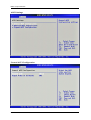
ME Subsystem Configuration
BootBlock HECI Message
The choice: Disabled, Enabled.
HECI Message
The choice: Disabled, Enabled.
End Of Post S5 HECI Message
The choice: Disabled, Enabled.
ME HECI Configuration
Enable/Disable ME-HECI, ME-IDER, ME-KT.
ME-HECI (Read Only)
This setting Enable the ME-HECI.
ME-IDER
The choice: Disabled, Enabled.
ROBO-8914VG2AR User’s Manual
4-36
BIOS Setup Information
ME-KT
The choice: Disabled, Enabled.
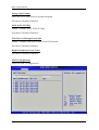
ME QST Configuration
Enable/Disable FAN Speed Monitor1, 2, 3.
FAN Speed Monitor1
The choice: Disabled, Enabled.
FAN Speed Monitor2
The choice: Disabled, Enabled.
FAN Speed Monitor3
The choice: Disabled, Enabled.
QST Configuration
The choice: Unlocked, Locked.
QST SST BUS
The choice: Unlocked, Locked.
QST Sensor Thresholds
The choice: Unlocked, Locked.
QST Manual Fan Ctrl
The choice: Unlocked, Locked.
QST Chipset
The choice: Unlocked, Locked.
Thermal Sensor
The choice: Displayed, Hidden.
ROBO-8914VG2AR User’s Manual
4-37
BIOS Setup Information
iQST Hardware Health Sensor Monitoring (Read Only)
ROBO-8914VG2AR User’s Manual
4-38
BIOS Setup Information
4.8
Exit
This menu allows you to load the BIOS default values or factory default settings into
the BIOS and exit the BIOS setup utility with or without changes.
Exit Saving Changes
Exit System Setup and save your changes to CMOS. Pressing <Enter> on this item
asks for confirmation: Save changes to CMOS and exit the Setup Utility.
Discard Changes and Exit
Abandon all changes and exit the Setup Utility.
Discard Changes
Abandon all changes and continue with the Setup Utility.
Load Optimal Defaults
Use this menu to load the default values set by the SBC manufacturer specifically for
optimal performance of the SBC.
Load Failsafe Defaults
Use this menu to load the default values set by the BIOS vendor for stable system
performance.
ROBO-8914VG2AR User’s Manual
4-39
Troubleshooting
Chapter 5
Troubleshooting
This chapter provides a few useful tips to quickly get ROBO-8914VG2AR running
with success. As basic hardware installation has been addressed in Chapter 2, this
chapter will primarily focus on system integration issues, in terms of BIOS setting,
and OS diagnostics.
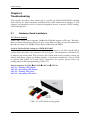
5.1
Hardware Quick Installation
ATX Power Setting
Unlike other Single board computer, ROBO-8914VG2AR supports ATX only. Therefore,
there is no other setting that really needs to be set up. However, there are only two connectors
that must be connected—PWR2 (24 pins Power Connector) and PWR1.
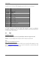
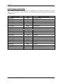
Serial ATA Hard Disk Setting for IDE/RAID/AHCI
Unlike IDE bus, each Serial ATA channel can only connect to one SATA hard disk at
a time; there are total four connectors, SATA1~4 port. The installation of Serial ATA
is simpler and easier than IDE, because SATA hard disk doesn’t require setting up
Master and Slave, which can reduce mistake of hardware installation. All you need
to operate IDE, RAID (0/1) and AHCI application for system, please follow up
setting guide in BIOS programming (Table 5-1).
Detect sequence: SATA1 SATA2 SATA3 SATA4
SATA1 -- Primary IDE Master
SATA2 -- Secondary IDE Master
SATA3 -- Primary IDE Slave
SATA4 -- Secondary IDE Slave
Table. 5-1 SATA Mode setting guide
ROBO-8914VG2AR User’s Manual
5-1
Troubleshooting
5.2
BIOS Setting
It is assumed that users have correctly adopted modules and connected all the
devices cables required before turning on ATX power. CPU, CPU Fan, 240-pin DDR3
SDRAM, keyboard, mouse, floppy drive, SATA hard disk, DVI-I connector, device
power cables, ATX accessories are good examples that deserve attention. With no
assurance of properly and correctly accommodating these modules and devices, it is
very possible to encounter system failures that result in malfunction of any device.
To make sure that you have a successful start with ROBO-8914VG2AR, it is
recommended, when going with the boot-up sequence, to hit “DEL” key and enter
the BIOS setup menu to tune up a stable BIOS configuration so that you can wake up
your system far well.
Loading the default optimal setting
When prompted with the main setup menu, please scroll down to “Load Optimal
Defaults”, press “Enter” and “Y” to load in default optimal BIOS setup. This will
force your BIOS setting back to the initial factory configuration. It is recommended
to do this so you can be sure the system is running with the BIOS setting that
Portwell has highly endorsed. As a matter of fact, users can load the default BIOS
setting any time when system appears to be unstable in boot up sequence.
Auto Detect Hard Disks
In the BIOS => Standard CMOS setup menu, pick up any one from
Primary/Secondary Master/Slave IDE ports, and press “Enter”. Setup the selected
IDE port and its access mode to “Auto”. This will force system to automatically pick
up the IDE devices that are being connected each time system boots up.
Improper disable operation
There are too many occasions where users disable a certain device/feature in one
application through BIOS setting. These variables may not be set back to the original
values when needed. These devices/features will certainly fail to be detected.
When the above conditions happen, it is strongly recommended to check the BIOS
settings. Make sure certain items are set as they should be. These include the COM1/
COM2 ports, USB ports, external cache, on-board VGA and Ethernet.
It is also very common that users would like to disable a certain device/port to
release IRQ resource. A few good examples are
Disable COM1 serial port to release IRQ #4
Disable COM2 serial port to release IRQ #3
Etc…
ROBO-8914VG2AR User’s Manual
5-2
Troubleshooting
A quick review of the basic IRQ mapping is given below for your reference.
IRQ#
IRQ #0
IRQ #1
IRQ #2
IRQ #3
IRQ #4
IRQ #5
IRQ #6
IRQ #7
IRQ #8
IRQ #9
IRQ #10
IRQ #11
IRQ #12
IRQ #13
IRQ #14
IRQ #15
Description
System Timer
Keyboard Event
Usable IRQ
COM2
COM1
Usable IRQ
Diskette Event
Usable IRQ
Real-Time Clock
Usable IRQ
Usable IRQ
Usable IRQ
IBM Mouse Event
Coprocessor Error
Hard Disk Event
Usable IRQ
It is then very easy to find out which IRQ resource is ready for additional
peripherals. If IRQ resource is not enough, please disable some devices listed above
to release further IRQ numbers.
5.3
FAQ
Installation Problem
Question:I forget my password of system BIOS, what am I supposed to do?
Answer: You can simply short 2-3 pins on JP3 to clean your password.
Note:
Please visit our technical web site at
http://www.portwell.com.tw
For additional technical information, which is not covered in this manual, you can
mail to [email protected] or you can also send mail to our sales, they wull
be very delighted to forward them to us.
ROBO-8914VG2AR User’s Manual
5-3
Appendix A
System Memory Address Map
Each On-board device in the system is assigned a set of memory addresses, which
also can be identical of the device. The following table lists the system memory
address used.
Memory Area
0000-003F
0040-004F
0050-006F
0700-0483
0484-053F
0540-9EFE
9EFE-9EFE
9F00-9FBF
9FC0-9FFF
A000-AFFF
B000-B7FF
B800-BFFF
C000-CAFF
CB00-CC49
CC4A-CFFF
D000-DFFF
E000-EEFF
EF00-EFFF
F000-FFFF
HMA
Size
Device Description
1K
Interrupt Area
0.3K
BIOS Data Area
0.5K
System Data
16K
DOS
2.9K
Program Area
614K
[Available]
0.1K
Unused
= Conventional memory ends at 640K =
3K
Extended BIOS Area
1K
Unused
64K
VGA Graphics
32K
Unused
32K
VGA Text
44K
Video ROM
5.2K
Unused
14K
High RAM
64K
Page Frame
60K
Unused
4K
ROM
64K
System ROM
64K
First 64K Extended
ROBO-8914VG2AR User’s Manual
Appendix B
Interrupt Request Lines (IRQ)
Peripheral devices can use interrupt request lines to notify CPU for the service
required. The following table shows the IRQ used by the devices on board.
IRQ#
IRQ 0
IRQ 1
IRQ 2
IRQ 3
IRQ 4
IRQ 5
IRQ 6
IRQ 7
IRQ 8
IRQ 9
IRQ 10
IRQ 11
IRQ 12
IRQ 13
IRQ 14
IRQ 15
Current Use
System ROM
System ROM
[Unassigned]
System ROM
System ROM
[Unassigned]
System ROM
[Unassigned]
System ROM
[Unassigned]
[Unassigned]
[Unassigned]
System ROM
System ROM
System ROM
IDE
ROBO-8914VG2AR User’s Manual
Default Use
System Timer
Keyboard Event
Usable IRQ
COM2
COM1
Usable IRQ
Diskette Event
Usable IRQ
Real-Time Clock
Usable IRQ
Usable IRQ
Usable IRQ
IBM Mouse Event
Coprocessor Error
Hard Disk Event
Usable IRQ