1
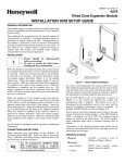
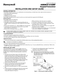
N8281V1 5/01 Rev. B 4209U Universal Group Zoning Multiplex Module INSTALLATION AND SETUP GUIDE FEATURES For all fire alarm (NFPA) certified installations, the 4209U must be tamper protected or mounted in a tamper-protected cabinet. The ADEMCO 4209U Group Zoning Multiplex Module is a 4-zone expander that allows use of available expansion zones provided by ADEMCO controls that support polling loop devices. Its primary purpose is to provide additional 2-wire smoke detector loops to the control. Other devices may be used, but all zones must be programmed for a fire response type. Characteristics of this device include: • Uniquely identifies 4 supervised zones or 2 supervised zones in the “grouped” mode (groups two supervised zones together into one zone). • Supports up to 16 2-wire smoke detectors on each of its 4 loops, regardless of group setting. • DIP Switches can be used to set zone numbers or serial numbers. • When used in the serial number mode, each serial number in the selected group can be assigned to any zone number. • Tamper protected. When the module is to be mounted inside the control’s cabinet tamper protection is not required if the cabinet is supervised. Insert self-tapping screws (provided) in two adjacent raised tabs at the back of the cabinet, leaving the heads projecting 1/8”. Hang the module on the screw heads via the two slotted holes on the back of the module’s housing. When the installation is complete install the cover and affix the Serial Number and Zone Assignment Tables to the inside cover of the control. WIRING CE MOUNTING 1. 2. Power should be disconnected before proceeding. Be sure to mount the 4209U before making any wire connections. For CE installations ADEMCO N6361 EMI suppression bead is required. Refer to the N6361 installation guide for wire routing instructions. Polling loop and protection loop wires can be brought in either through the back or front of the unit by removing the knockouts. Use 22 gauge twisted pair wire for polling loop connections. All protection loops use 2k EOL resistors (included). A maximum resistance of 100 ohms is allowed on protection loops (excluding EOLR). See Figure 2 for all connections. Keep in mind that even in the grouped mode, each set of terminals must have its own 2k EOLR, and it must be connected across the loop wires at the last detector. When mounted remotely tamper protection is required. Holes on the back of the module’s housing permit it to be mounted horizontally or vertically. Wires can exit from the side or the breakout on the back of its housing. To enable tamper protection, set DIP Switch 8 to OFF and attach the tamper magnet (provided) (Figure 1) to the module inside cover. Be sure to enable the expansion zone tamper option at the control (program field *24 = 0). When the installation is complete install the cover and affix the Serial Number and Zone Assignment Tables to the inside cover of the control. If the modules cover is removed, the magnet attached to the cover, positioned near the reed switch, will cause a tamper signal to be sent to the control for every active zone on the 4209U module. Power Connections must be made so that power to the smoke detectors can be momentarily interrupted to clear the alarm. This can be done either via the control’s auxiliary relay (if supported) or through a relay on a 4204 relay module. Wire the common of the relay to 12VDC and the N.C. contact on the 4209U (TB2, terminal 3). The relay you use must be programmed for “Smoke Protector Reset” (see control panel’s instructions). When you reset an alarm at the keypad, the relay arm will swing momentarily to the N.O. contact, causing an interruption of power. DIP SWITCH SETTINGS ZONE ASSIGNMENT MODE: In the zone assignment mode, the DIP Switches on the 4209U are used to assign the unit to a group of 4 consecutive zones in the “non-grouped” mode, or 2 consecutive zones in the “grouped” mode. These zone numbers, once designated for the 4209U, cannot be used for anything else, even if you don’t use them all. Follow the steps below using Table 1 for DIP Switch settings. Serial Number Mode: 1. INSERT BOTTOM TABS FIRST. 2. ENGAGE TOP WITH CLIP. In the serial number mode, the DIP Switches on the 4209U are used to assign the unit to a group of 4 serial numbers, or 2 serial numbers in the “grouped” mode. You can assign any serial number to any zone number (except hardwire zone numbers on the control) and you do not lose zone numbers if you don’t use all 4 loops on the 4209U. Follow the steps below using Table 2 for DIP Switch settings. 4219-002-V0 Figure 1. Tamper Magnet Installation 1 4209U ON 2 3 5 TB2 POSITIONS 2-5: SELECT THE 2 (GROUPED) OR 4 (NON GROUPED) SENSOR DEVICE GROUP ADDRESS (SHOWN ON, ON, ON, OFF = 2nd GROUP SELECTION). 6 7 8 OFF SELECT GROUP MODE (SHOWN OFF = NON GROUPED). ON O N 1 4 } POSITION 1: ON DEVICE TYPE (SHOWN ON = “SERIAL NUMBER” MODE). POSITION 7: NOT USED. SET TO “OFF.” POSITION 8: SELECT TAMPER PROTECTION SETTING (SHOWN OFF = TAMPER ENABLED). SIDEVIEW ( ) GND 4 POSITION 6: (+) 12VDC SWITCHED POWER SOURCE, (VIA CONTROL PANEL’S AUXILIARY RELAY OR 4204 RELAY MODULE). 3 2 ( ) 1 REED (TAMPER) SWITCH (+) TB1 1 (+) LOOPS: THE EOL RESISTOR MUST BE CONNECTED ACROSS THE LOOP WIRES AT THE LAST DETECTOR 2 ( ) A (+) ( ) 4 3 (+) ( ) B (+) 5 (+) 6 ( ) C 7 (+) (+) ( ) SMOKE ( ) SMOKE SMOKE 2k EOLR 2k EOLR 8 } TO POLLING LOOP (USE TWISTED PAIR) ( ) D NOTE FOR CE INSTALLATIONS A N6361 EMI SUPPRESSION BEAD IS REQUIRED. (+) ( ) SMOKE UP TO 16 2-WIRE SMOKE DETECTORS 2k EOLR 2k EOLR MAX OF 100 ohms WIRING RESISTANCE AND 2k EOLR 4209U-SOC-V0 Figure 2: Summary of Connections For “Zone Assignment” mode, DIP Switch position 6 must be off. When using this mode, program each zone’s “Input Type” as “DIP Switch Polling Loop Device” (DP), where applicable. THIS SWITCH SETTING PRESETS THE LOOPS TO THESE ZONE NUMBERS Loop Number DIP Switch Position (“-” Means “off”) NON-GROUPED 3 On On On On On On On On - 4 On On On On On On On On - 5 On On On On On On On On - 6 - Loop A 1 9 17 25 33 41 49 57 65 73 81 89 97 105 113 121 Loop B 2 10 18 26 34 42 50 58 66 74 82 90 98 106 114 122 Loop C 3 11 19 27 35 43 51 59 67 75 83 91 99 107 115 123 Loop D 4 12 20 28 36 44 52 60 68 76 84 92 100 108 116 124 GROUPED Loop A&B Loop C&D 1 2 9 10 17 18 25 26 33 34 41 42 49 50 57 58 65 66 73 74 81 82 89 90 97 98 105 106 113 114 121 122 ** Zone Number 2 On On On On On On On On - *** *Do not select 1 – 4 for VISTA controls. **If 9 – 12 is selected for controls that have 9 hardwire zones. First Loop (Zone 9) will be inactive. ***4209U also accommodates option “ONE 4208 IN USE” if referred to in control programming. NOTE: Consult the Control Panel Instructions to determine the valid zone numbers for that control panel. Table 1. 4209U Zone Number Assignments For “Serial Number” mode, DIP Switch position 6 must be on. 2 ON ON ON ON ON ON ON ON - THIS SWITCH SETTING PRESETS THE LOOP TO THESE SERIAL NUMBERS Loop Serial Number DIP Switch Position (Each serial number in the selected group can be assigned to any zone number.) (“-” Means “off”) NON-GROUPED GROUPED 3 4 5 6 LOOP A LOOP B LOOP C LOOP D LOOP A&B LOOP C&D ON ON ON ON 000-0004 000-0005 000-0006 000-0007 000-0004 000-0005 ON ON ON 006-9908 006-9909 006-9910 006-9911 006-9908 006-9909 ON ON ON 013-9812 013-9813 013-9814 013-9815 013-9812 013-9813 ON ON 020-9716 020-9717 020-9718 020-9719 020-9716 020-9717 ON ON ON 027-9620 027-9621 027-9622 027-9623 027-9620 027-9621 ON ON 034-9524 034-9525 034-9526 034-9527 034-9524 034-9525 ON ON 041-9428 041-9429 041-9430 041-9431 041-9428 041-9429 ON 048-9332 048-9333 048-9334 048-9335 048-9332 048-9332 ON ON ON ON 055-9236 055-9237 055-9238 055-9239 055-9236 055-9237 ON ON ON 062-9140 062-9141 062-9142 062-9143 062-9140 062-9141 ON ON ON 069-9044 069-9045 069-9046 069-9047 069-9044 069-9045 ON ON 076-8948 076-8949 076-8950 076-8951 076-8948 076-8949 ON ON ON 083-8852 083-8853 083-8854 083-8855 083-8852 083-8853 ON ON 090-8756 090-8757 090-8758 090-8759 090-8756 090-8757 ON ON 097-8660 097-8661 097-8662 097-8663 097-8660 097-8661 ON 104-8564 104-8565 104-8566 104-8567 104-8564 104-8565 Table 2. 4209U Serial Number Assignments 2 Set the DIP switches on the 4209U as instructed below: 1. Select “grouped” or “non-grouped” mode using DIP Switch 1: Grouped = ON Non-grouped = OFF. 2. Select mode of operation (serial number or zone assignment mode) using DIP Switch 6: Serial Number mode = ON Zone Assignment mode = OFF. 3. Select the group setting using DIP Switches 2, 3, 4, and 5. See Table 1 for zone assignments or Table 2 for serial number assignments. If using more than one 4209U, be sure to set each one to a different group setting. 4. DIP Switch 7: Not used, set to OFF. 5. Select the 4209U Tamper Protection setting using DIP Switch 8: Tamper Disabled = ON Tamper Enabled = OFF. Tamper will report for every active zone on the 4209U module. All zones assigned to the 4209U must be programmed as Fire zones (zone type 09 or 16). When setting the 4209U to a group of zone numbers, each zone must be programmed as follows: On 4140XMP and earlier controls, these zones must be programmed as Left Loop Polling Loop Zones. • On VISTA-40 and later controls, these zones must be programmed in the #93 Menu Mode Zone Programming as INPUT TYPE “7” – DP (DIP Switch type polling device). Replace the 4209U cover and clear the keypad of any faulted zones. 4. Remove the 4209U’s cover and verify (on the keypad) that only the zones you designated for this 4209U are indicating a check (or trouble) condition. Ionization, direct wire Ionization with B110LP base Ionization, direct wire Ionization with B401B base Ionization duct detector w/ DH400 base Photoelectric, direct wire Photoelectric w/heat sensor, direct wire Photoelectric w/B110LP base Photoelectric, direct wire Photoelectric w/heat sensor, direct wire Photoelectric w/B401B base Photoelectric w/heat sensor and B401B base Photoelectric dust detector w/ DH400 base PROGRAMMING • 3. System Sensor 2451DH From Polling Loop From Switched Power 15.5mA 110mA SPECIFICATIONS Sensor Loop Response: Physical: 400 msec (all loops) Width: 6-7/16”(163mm) Sensor Loop Current @ switched power input of 12VDC: Height: 4-1/4” (108mm) Depth: 1-1/4” (32mm) 7.7mA (normal) Electrical: Polling loop input: VDC 25mA (shorted) 6.7 – 14 Switched Power Input: 10.2 to 14VDC Current draw: 15.5mA max. from polling loop, 110mA max. from switched power source (see Table 4) VERIFICATION OF PROGRAMMING To verify proper programming, the following test should be performed: Set DIP Switch 8 to OFF (tamper enabled). System Sensor 2451 System Sensor 2451TH Table 4. Current Draw Calculations If learning a serial number by faulting its associated loop, make sure that other polling loop devices are not activated, as they may interfere with the device being learned. 2. System Sensor 2151 System Sensor 2400 System Sensor 2400TH Current Draw (All zones shorted) (Input Voltage: 11 – 14VDC) When prompted to learn the serial number for a particular zone, you may either enter it manually through the keypad or through VLink, or “learn” it by momentarily faulting (shorting) the terminals of that zone as required by the control. If entering a serial number manually through the keypad, enter it and press “*” to advance to the next prompt. Make sure you also enter the loop number of the device you are using for that zone (see the control’s instructions for more details about learning serial numbers). If learning or entering a serial number, and the message “Duplicate of Zone XX” is displayed, another device with that same serial number is already in the system. In that case, use a different serial number group setting on the 4209U. Be sure to enable expansion zone tamper protection at the control (program field *24 = 0). System Sensor 2100 System Sensor 2100T Table 3. Compatible 2-Wire Smoke Detectors When setting the 4209U to a group of serial numbers, each zone must be programmed as INPUT TYPE “6” --SL (Serial Number Polling Loop Device). Loops can be learned in any order and assigned to any legitimate zone number. 1. System Sensor 1100 System Sensor 1151 System Sensor 1400 System Sensor 1451 System Sensor 1451DH 3 Sensor Loop Resistance: Max. Up to 100 ohms of wire resistance + 2k EOLR. LIMITED WARRANTY Honeywell International Inc., 165 Eileen Way, Syosset, New York 11791, warrants its product(s) to be in conformance with its own plans and specifications and to be free from defects in materials and workmanship under normal use and service for 24 months from the date stamp control on the product(s) or, for product(s) not having a date stamp, for 12 months from date of original purchase unless the installation instructions or catalog sets forth a shorter period, in which case the shorter period shall apply. Seller's obligation shall be limited to repairing or replacing, at its option, free of charge for materials or labor, any product(s) which is proved not in compliance with Seller's specifications or proves defective in materials or workmanship under normal use and service. Seller shall have no obligation under this Limited Warranty or otherwise if the product(s) is altered or improperly repaired or serviced by anyone other than Honeywell factory service. For warranty service, return product(s) transportation prepaid, to Honeywell Factory Service, 165 Eileen Way, Syosset, New York 11791. THERE ARE NO WARRANTIES, EXPRESS OR IMPLIED, OF MERCHANTABILITY, OR FITNESS FOR A PARTICULAR PURPOSE OR OTHERWISE, WHICH EXTEND BEYOND THE DESCRIPTION ON THE FACE HEREOF. IN NO CASE SHALL SELLER BE LIABLE TO ANYONE FOR ANY CONSEQUENTIAL OR INCIDENTAL DAMAGES FOR BREACH OF THIS OR ANY OTHER WARRANTY, EXPRESS OR IMPLIED, OR UPON ANY OTHER BASIS OF LIABILITY WHATSOEVER, EVEN IF THE LOSS OR DAMAGE IS CAUSED BY THE SELLER'S OWN NEGLIGENCE OR FAULT. Seller does not represent that the product(s) it sells may not be compromised or circumvented; that the product(s) will prevent any personal injury or property loss by burglary, robbery, fire or otherwise; or that the product(s) will in all cases provide adequate warning or protection. Customer understands that a properly installed and maintained alarm system may only reduce the risk of a burglary, robbery, fire, or other events occurring without providing an alarm, but it is not insurance or a guarantee that such will not occur or that there will be no personal injury or property loss as a result. CONSEQUENTLY, SELLER SHALL HAVE NO LIABILITY FOR ANY PERSONAL INJURY, PROPERTY DAMAGE OR OTHER LOSS BASED ON A CLAIM THAT THE PRODUCT(S) FAILED TO GIVE WARNING. HOWEVER, IF SELLER IS HELD LIABLE, WHETHER DIRECTLY OR INDIRECTLY, FOR ANY LOSS OR DAMAGE ARISING UNDER THIS LIMITED WARRANTY OR OTHERWISE, REGARDLESS OF CAUSE OR ORIGIN, SELLER'S MAXIMUM LIABILITY SHALL NOT IN ANY CASE EXCEED THE PURCHASE PRICE OF THE PRODUCT(S), WHICH SHALL BE THE COMPLETE AND EXCLUSIVE REMEDY AGAINST SELLER. This warranty replaces any previous warranties and is the only warranty made by Seller on this product(s). No increase or alteration, written or verbal, of the obligations of this Limited Warranty is authorized. FEDERAL COMMUNICATIONS COMMISSION (FCC) Part 15 STATEMENT This equipment has been tested to FCC requirements and has been found acceptable for use. The FCC requires the following statement for your information: This equipment generates and uses radio frequency energy and if not installed and used properly, that is, in strict accordance with the manufacture’s instructions, may cause interference to radio and television reception. It has been type tested and found to comply with the limits for Class B computing device in accordance with the specifications in Part 15 of FCC Rules, which are designed to provide reasonable protection against such interference in a residential installation. However, there is no guarantee that interference will not occur in a particular installation. If this equipment does cause interference to radio or television reception, which can be determined by turning the equipment off and on, the user is encouraged to try to correct the interference by one or more of the following measures: • If using an indoor antenna, have a quality outdoor antenna installed. • Reorient the receiving antenna until interference is reduced or eliminated. • Move the radio or television receiver away from the receiver/control. • Move the antenna leads away from any wire runs to the receiver/control. • Plug the receiver/control into a different outlet so that it and the radio or television receiver are on different branch circuits. If necessary, the user should consult the dealer or an experienced radio/television technician for additional suggestions. The user or master may find the following booklet prepared by the Federal Communications Commission helpful: “Interference Handbook” This booklet is available from the U.S. Government Printing Office, Washington, DC 20402. The user shall not make any changes or modifications to the equipment unless authorized by the Installation Instructions or User’s Manual. Unauthorized changes or modifications could void the user’s authority to operate the equipment. SEE THE CONTROL PANEL’S INSTALLATION INSTRUCTIONS FOR COMPLETE INFORMATION REGARDING THE LIMITATIONS OF THE ENTIRE SECURITY SYSTEM. 165 Eileen Way, Syosset, NY 11791 Copyright 2004 Honeywell International Inc. www.honeywell.com/security ¬197l N8281V1 5/01 Rev. B