1
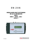
EN-206 I
HIGH DEFINITION ISDB-T MODULATOR
- 0 MI2067 -
SAFETY NOTES
Read the user’s manual before using the equipment, mainly "SAFETY RULES"
paragraph.
on the equipment means "SEE USER’S MANUAL". In this manual
The symbol
June also appear as a Caution or Warning symbol.
WARNING AND CAUTION statements June appear in this manual to avoid injury
hazard or damage to this product or other property.
USER'S MANUAL VERSION
Version
3.0
Date
June 2015
Software Version
3.1
SAFETY RULES
* The safety could not be assured if the instructions for use are not closely
followed.
* When using some of the following accessories use only the specified ones to
ensure safety.:
External DC charger
Power cord
* No use the external DC power cord this is damaged.
* Do not connect the external DC power until all cables are connected properly.
* In el manipulate external DC power supply.
* Observe all specified ratings both of supply and measurement.
* Remember that voltages higher than 70 V DC or 33 V AC rms are dangerous.
* Use this instrument under the specified environmental conditions.
* If the encoder modulator has been kept in cold conditions for a long time, keep it in
a warm room minimum 2 hours before plugging into the mains.
* Mount the device in vertical position with the connectors located on the top side.
* Do not obstruct the ventilation system of the instrument.
* To prevent fire or shock hazard, do not expose this appliance to rain or moisture.
* Use for the signal inputs/outputs, appropriate low radiation cables.
* Follow the cleaning instructions described in the Maintenance paragraph.
* The operator is not allowed to intervene within the team: Any other change on the
equipment should be carried out by qualified personnel.
* Mechanical handling / electric unit can cause damage. Do not connect the appliance
to the mains before or during assembly.
June 2015
* Symbols related with safety:
Descriptive Examples of Over-Voltage Categories
Cat I
Low voltage installations isolated from the mains.
Cat II Portable domestic installations.
Cat III Fixed domestic installations.
Cat IV Industrial installations.
June 2015
TABLE OF CONTENTS
1 INTRODUCTION ........................................................................................ 1
1.1 Description ....................................................................................... 1
1.2 Equipment Details ............................................................................. 2
1.3 Installation ....................................................................................... 3
1.4 Cascade Installation ........................................................................... 5
2 OPERATIONS AND MANAGEMENT .............................................................. 6
3 MENU TREE ............................................................................................... 8
4 USB PORT ................................................................................................16
4.1 TS Recorder and Save .......................................................................16
4.1.1 Description ..................................................................................16
4.1.2 Operation ....................................................................................18
4.2 TS Playback .....................................................................................19
4.3 USB upgrade....................................................................................20
4.4 Disk Usage ......................................................................................20
4.5 Remove Device ................................................................................21
5 TS CREATOR SOFTWARE...........................................................................22
5.1 Installation ......................................................................................22
5.2 Operations of "TS Creator".................................................................23
5.3 File Management ..............................................................................24
6 WEB-SERVER OPERATION ........................................................................26
6.1 Login ..............................................................................................26
6.2 Operation ........................................................................................27
7 SPECIFICATIONS .....................................................................................39
8 MAINTENANCE .........................................................................................41
8.1 Cleaning Recommendations ...............................................................41
June 2015
HIGH DEFINITION ISDB-T MODULATOR
EN-206 I
1 INTRODUCTION
1.1
Description
The EN-206 I which allow audio/video signal input in TV distributions with
applications in home entertainment, surveillance control, hotel Digital Signage,
shops etc. It is an all-in-one device integrating MPEG4 AVC/H.264 encoding and
ISDB-T modulating to convert input signals to ISDB-T RF out in the frequency
range of 30~1000 MHz.
The USB port is designed to record encoded video (TS) and save it in ts files in
the USB Keys or Hard Disks, and then the ts files can be playback through the
USB port. The ts files can be also generated on a computer with TS Creator.exe
program.
The signals source could be from satellite receivers, closed-circuit television
cameras, blu-ray players, and antenna etc. its output signal is to be received by
ISDB-T standard TVs or ISDB-T STBs etc.
Figure 1. System Connection Chart.
June 2015
1
1.2
Equipment Details
Front View
Figure 2.
Up View
Figure 3.
► Grounding: To connect the earth cable.
► DC 12V: Power Input.
► HDMI: HDMI stream input supporting HD signals.
► YPbPr + S-Video + AV: YPbPr + S-Video + AV signal input through a VGA
adapter cable.
► RF in: RF Loop-through input.
► RF Output: RF output to distribute modulated signal.
► USB Port: For video record, playback and system upgrade.
► Ethernet Port: For web-server management.
2
June 2015
1.3
Installation
Mount and tighten the screws and plugs to secure the unit to the wall.
Left 10 cm of free space around from each unit.
Connect the signal input in the respective connectors. The signal source
can be from a surveillance monitor, DVD, set-top box, CCTV and etc.
Optionally, connect the loop-through RF input coaxial cable.
Connect cable to RF output to STB/TV.
Power supply connection: a) Connect the earth cable; b) Connect the
power plug to the unit mains connector; c) Connect the power plug to the
mains socket.
Figure 4.
June 2015
3
Figure 5.
4
June 2015
1.4
Cascade Installation
The unit has 1 TV signal to RF output encoded as ISDB-T Digital TV signal.
Several units can be cascaded in order to increase the capacity. The maximum
capacity of a series of N units is 1xN incorporated TV signals. To cascade 2 or
more units, connect the RF output of the preceding unit to the TV input (loopthrough) of the next unit (see illustration).
Figure 6.
June 2015
5
2 OPERATIONS AND MANAGEMENT
The unit is controlled and managed through the keyboard and LCD display.
Figure 7.
► LCD Display:
It presents the selected menu and the parameter settings. The backlight in
the display is on when the power is applied.
► LED:
These lights indicate the working status.
Power:
It lights on when the power supply is connected.
Alarm:
It lights on when the there is error, such as the signal
source loss.
USB:
It lights on when the USB device is properly connected
and blocks out when the USB device get removed.
► Left/Right/Up/Down buttons:
Use these buttons to turn the screen pages, shift the target items by moving
the triangle, or change the parameter settings in the program mode.
6
June 2015
► Enter
Use this button to enter a submenu or save a new setting after adjustment;
press it to start adjusting the value of certain items when the corresponding
underline flash with Up and Down buttons.
Figure 8.
Press it to activate the hidden selections and change the setting with Up and
Down (or Left and Right) buttons.
Figure 9.
► Menu:
Press this button to step back.
► Lock:
Locking the screen / cancelling the lock state, and entering the main menu
after the initialization of the device. After pressing lock key, the system will
question the users to save present setting or not.
If not, the LCD will display the current configuration state.
After the initialization of the device, press LOCK to unlock the keyboard. Then
you will be able to browse in the menu tree.
June 2015
7
3 MENU TREE
When the power is connected, the LCD will start to initialize the program. After
the initialization of the device, press LOCK to unlock the keyboard. Then you will
be able to browse in the menu tree.
The LCD menu goes as below chart. Numbers on the menu refers to the numbers
on the menu tree.
8
June 2015
June 2015
9
Figure 10. ISDB-T menu Tree.
10
June 2015
1. ISDB-T:
Modulating standard.
XX.XXX MHz: The current output frequency.
576i: Video resolution of signal source.
X.XX Mbps: The current encoding bit rate
2. Alarm Status:
It displays alarm messages. For example, if the CVBS cable
disconnected, it will display Video 1 Not Lock under this
menu.
3. Uptime:
It displays the working time duration of the device. It times
upon power on.
4. Video:
User can enter
parameters.
the
items
respectively
to
set
video
Interface: Select a right interface type from the options
provided. The device then can automatically search the
signal and starts to encode.
Resolution: Signal source resolution, read-only.
Video Bitrate: Adjust in range of 1.000~19.000 Mbps.
Rate Mode: This unit user can choose CBR or VBR.
User can also adjust values of rest items (H.264 profile,
H.264 level, Brightness: 0-128 & Contrast: 0-255 &
Saturation: 0-128; Hue: -128 - +127).
5. Audio:
Audio Bitrate: Select audio bit rate from the options
provided. Different audio format has different bit-rate
range. See specification table for details.
Audio format: Seleccione el formato de audio entre
MPEG2, MPEG2-AAC y MPEG4-AAC.
HDMI audio input (Entrada de audio HDMI): Choose to
input HDMI audio or not.
June 2015
11
6. Program Information:
User can enable or disable the program output under menu
Program Output. User can also enter the other items to
edit the Service Name, Program Name, Program
Number, and PIDs of PMT, PCR, Video and Audio, and
edit LCN (Logical channel number).
7. TSID (Transport Stream ID):
User can view or adjust after enter this menu.
8. ONID (Original Network ID):
User can view or adjust after enter this menu.
9. NIT (Network Information Table):
NIT table is a very important table for describing the
network and TS. User can enter the submenus displayed
and edit the values or select the LCN (Logical channel
number) mode, and choose whether to insert the NIT. If
user chooses to insert the NIT information (Network ID,
Network Name and other parameters) will be added to the
transport stream.
NOTE: When the Private Data is set as 0*0, it is invalid.
10. Constellation:
ISDB-T/Tb modulator contains these constellation modes:
DQPSK, QPSK, 16QAM and 64QAM.
11. FFT (Transmission Mode):
Select between 2K, 4K and 8K.
12. Guard Interval:
Select among 1/32, 1/16, 1/8 and 1/4.
13. Code rate:
It refers to FEC-Forward Error Correction rate. It contains
1/2, 2/3, 3/4, 5/6 and 7/8.
different
combination
of
bandwidth,
NOTE: The
constellation, guard interval and code rate (FEC) will form a
different output code rate.
12
June 2015
14. RF Frequency:
Adjust it at range of 30 to 999 MHz. Set it according your
regional situation or inquire your local services.
15. RF Level:
Adjust it at range of -16~ -36dBm.
16. RF On:
User can choose to turn on or turn off the RF under this
menu.
17. Bitrate:
User can read the current modulating bit rate and the
maximum bit rate
18. Change modulator: User can select the modulation
standard at this menu in accordance with the TV standard
used to receive the output RF. After selecting the
Modulation standard, user needs to restart the device.
19. Delete modulator: User can choose to delete
modulation mode(s) which you June never use from the
device.
CAUTION: The deleted modulation mode(s) cannot
be restored without the right upgrade software from the
factory. In such case, ask the factory for help.
20. NMS IP:
To configure IP address here (by default 192.168.0.136).
21. Subnet Mask:
To configure subnet mask here (by default 255.255.255.0).
22. Gateway:
To configure gateway here (by default 192.168.0.1).
23. MAC Address:
To view MAC address here.
June 2015
13
24. Web NMS Port (Web Port):
To configure web port here (by default 80).
25. Reset password:
It resets the password.
26. Please refer to chapter "USB port" for details.
27. Please refer to chapter "USB port" for details.
28. Please refer to chapter "USB port" for details.
29. Please refer to chapter "USB port" for details.
30. Please refer to chapter "USB port" for details.
31. Save Config:
Yes/No to save/give up the adjustment of setting.
32. Load Saved CFG:
Yes/No to load/ not to load the saved configuration.
33. Reset all sets:
Yes/No
choose/not
configuration.
choose
the
factory’s
default
34. LCD Time out:
A time limit that LCD will light off. Choose among 5s, 10s,
45s, 60s, 90s and 120s (seconds).
14
June 2015
35. Set password:
User can set a 6 digital password used to unlock the
keyboard.
36. Lock Keyboard:
Choose Yes to set a password and lock the keyboard, then
the keyboard will be locked and cannot be applicable. It is
required to input the password to unlock the keyboard. This
operation is one-off. (If forgetting your password, please
use the universal code “000000”.)
37. Product ID:
User can view the serial number of this device. It is readonly and unique.
38. Version:
It shows information of the device.
Encoder modulador: device name.
SW: software version number.
HW: hardware version number.
June 2015
15
4 USB PORT
Using a USB flashdrive connected to the USB port it can perform several
functions, which are described in the following sections.
4.1
TS Recorder and Save
4.1.1
Description
► TS Recorder:
EN-206 I can encode the source video to *.ts files and save them through the
USB flash drive.
Connect the signal source to EN-206 I and start encoding process.
Start the record process and save the TS generated to the USB flash drive.
► TS Playback
Insert the USB flash drive with *.ts videos in EN-206 I and play back the
content in an easy way.
A single video can be up to 2G in size and multi videos can be played on a
loop.
► *.ts Video Creation Software
Users can also create *.ts videos containing pictures, videos and music with
our Creator software on a PC and save them into the USB flash drive.
Drag the files to “Creator” application. Formats supported include:
Image:
Audio:
Video:
JPG, PNG, BMP, GIF.
MP3, WAV.
WMV, MPG, MP4, TS, AVI.
Start the conversion process to generate *ts videos
For more details see chapter "TS Creator Software".
16
June 2015
USB Flash Drive Specifications Required:
* Standard: High speed 2.0 / 3.0
* File system: FAT 32
Figure 11.
June 2015
17
4.1.2
Operation
Figure 12.
Connect the signal source, enter "Start Record" and choose "Yes" to
start recording the encoded TS.
Advanced Config:
► File size:
Users can set the file size for the *.ts to be recorder. A single file can
be maximum 2000 MB in size.
► Filter null PKT:
Users can decide whether to filter the null packet for the *.ts files to
be recorded.
► Filter save mode:
There are 3 modes provided:
"Single file": For example, when the file size is set as 1000 MB
and the *.ts is recorded up to 1000 MB, it automatically stops
recording TS.
"Segmented file": For example, when the file size is set as
1000 MB and the *.ts is recorded up to 1000 MB, it automatically
saves the files and continues to record TS and save it to next file
until the USB memory is full.
"Loop record": It automatically saves the files and continues to
record TS and save it to next file. When the USB memory is full, it
replaces the previous files.
► File name:
Users can enter this menu to edit name for the *.ts files to be
recorded. For example, if users name it “Record-“, it will give name to
the saved *.ts files "Record-001.ts", "Record-002.ts"... "Record00N.ts"
► Automatic Record:
Users can cose whether to record the TS automatically or manually.
18
June 2015
4.2
TS Playback
Figure 13.
Play stop: Choose “Yes” to stop TS play. Choose “No” to start TS play.
File browse: There is a video list under this menu, choose one file and
press “Enter” button to start play.
Play mode: User can select a play mode for the saved *.ts files as
hended before playing the *.ts file.
When the *.ts is being playing, LCD will present a playing interface as
shown below.
Figure 14.
Symbol of play-mode.
Single loop
Play all
Loop all
Single file
File name being playing.
The played percentage of the current file.
The size of the current file.
June 2015
19
At this time, the key board also plays a different rule:
Figure 15.
Select file.
Rewind.
Forward.
Play/Pause.
Stop Playing.
Step back to main menu.
Automatic play: When the auto mode is enabled, the device will
automatically play after USB connected. Otherwise user needs to click
“Play stop” button to start.
4.3
USB upgrade
Figure 16.
Choose one item to be updated and press Enter to confirm. Keep the update file
stored in the USB device in the name of “Encoder Modulator-XXX.tar.gz” (XXX =
FPGA or CPU according to the component to be updated).
4.4
Disk Usage
Figure 17.
Users can enter this menu to view the USB total and free disk memory.
20
June 2015
4.5
Remove Device
Figure 18.
Choose "Yes" to safely remove the USB disk. EN-206 I will then automatically
resume encoding and playing the program input from the encoder module.
June 2015
21
5 TS CREATOR SOFTWARE
EN-206 I encoder modulator has a function to create TS videos with the
software associated with the product. Users can create *.ts files containing
images, videos and audios in a simple and intuitive way, and play them on a
television through EN-206 I usb port. Supported format files are:
Image:
Video:
Audio:
5.1
JPG, PNG, BMP, GIF
MP4, WMV, AVI, MPG, TS, MKV
MP3, WAV
Installation
Access download are "Software and firmware" at the PROMAX website and
select your equipment in the drop down menu. It will appear all the
software for that equipment.
Download our "TS Creator" software package on your PC to get the installer
and its auxiliary routine.
Occasionally, if your PC hasn’t installed "Net frame 2.0" yet, double-click
"NetFX20SP2_x86.exe" until complete the installation.
Double-click "Setup.exe" application to install the "TS Creator" and generate
a desktop shortcut.
22
June 2015
5.2
Operations of "TS Creator"
Double-click the "Creator" shortcut icon, it will trigger an operation interface like
below:
Figure 19.
Click to add images and videos.
Click to adjust the order of Images/Videos.
Click to delete the Images/Videos.
Click to add audios.
Click to set a save path for the TS video to be created.
To set time duration for every picture when playing the video.
To set the resolution for the output video.
The video is transformed based on VBR (Variable Bit Rate). The number
set here represents the highest bit rate for the output video and bit rate
will varies under the number.
June 2015
23
Users can select a encode format here according to standard of receiving
terminal.
Users can filter the null packet to boost the video’s effect bit rate.
A single video can be maximum 2.0 GB in size. (EN-206 I cannot play a
video bigger than 2 GB).
After setting all the parameters, click
to start the transformation. Click
"OK" when it prompts "The operation completed normally".
Click this button to stop the transformation before the operation
completed.
After finishing the transform operation, users can clic this button to play
the generated TS video.
5.3
File Management
After finishing the transformation, users can find out the videos files generated
according the Saving Directory. For example, we save the video in “D:\ABC” so
we can find it in Disk D\Folder ABC.
► Management:
Three files will be generated if the Null Packet has been filtered.
Figure 20.
File TS video for preview through the “Creator” interface by clicking
“Play” button.
File TS video and information files: Users need to save the two files
together in the USB memory, and then EN-206 I can read them
and play the video.
24
June 2015
Two files will be generated if the Null Packet has been filtered.
Figure 21.
File TS video for preview through the “Creator” interface by clicking
“Play” button.
File TS video: Users need to save it in the USB memory, and then
EN-206 I can read it and play the video.
► Remarks:
All the file names are automatically generated.
Rename the files before creating a new video to avoid covering the
previous files.
If you rename "FinalOutput-204-0.ts" or "FinalOutput-204-0.tsinfo",
always sep the names the same (Extensión excluded) and then EN-206 I
can read them and play the video.
June 2015
25
6 WEB-SERVER OPERATION
In addition to using front buttons to control the encoder modulator and USB
device, users can also perform the same operation in an easier way with the web
Brower in the PC (Personal Computer).
6.1
Login
The default IP address of this device is 192.168.0.136. (We can modify the IP
through the front panel.)
Connect the PC and the encoder modulator with a net cable, and use ping
command to confirm they are on the same network segment.
I.G. the PC IP address is 192.168.99.252, we then change the device IP to
192.168.99.xxx (xxx can be 1 to 254 except 252 to avoid IP conflict).
Use web browser to connect the device with PC by inputting the device’s IP
address in the browser’s address bar and press Enter.
It will display the Login interface. Input the Username and Password (Both the
default Username and Password are “admin”.) and then click “LOGIN” to start
the device setting.
Figure 24.
26
June 2015
6.2
Operation
When we confirm the login, it displays the WELCOME interface as figure below
where users can have an overview of the device’s system information and
working status.
Figure 25.
June 2015
27
Parameters – Input
From the menu on left side of the webpage, clicking “Input”, it displays the
interface where users can configure the encoding parameters for the input
video/audio (see figure).
NOTE: Items in this interface varies when different modulation mode is chosen as
the current mode. This user manual here takes DVB-T modulation mode
as example to display.
Figure 26.
28
June 2015
Parameters – TS Config
From the menu on left side of the webpage, clicking “TS Config”, it displays the
interface where users can configure the parameters for the transport stream as
prompt (see figure).
Figure 27.
June 2015
29
Parameters – Modulator
From the menu on left side of the webpage, clicking “Modulator”, it displays
the interface where users can configure the modulating parameters for the RF
output (see figure). User can select a different modulation standard at
“System → Device” interface.
Figure 28.
30
June 2015
Parameters – USB Media
From the menu on left side of the webpage, clicking “USB Media”, it displays
the interface where users can operate USB device (see figure).
NOTE: It is necessary to connect USB device and signal source and activate
encoding to operate TS recording.
NOTE: It is necessary to connect USB device when operate TS playing.
Figura 29.
► Record TS
File Save Mode
“Single file”: For example, when the file size is set as 1000M and the *.ts is
recorded up to 1000M, it automatically stops recording TS.
“Segment file”: For example, when the file size is set as 1000M and the *.ts
is recorded up to 1000M, it automatically saves the files and continues to
record TS and save it to next file until the USB memory is full.
“Loop record”: It automatically saves the files and continues to record TS
and save it to next file. When the USB memory is full, it replaces the
previous file.
June 2015
31
File name: Users can enter this menu to edit name for the *.ts files to be
recorded. For example, if users name it “Record-”, it will give name to the
saved *.ts files “Record-001.ts”, “Record-002.ts”… “Record-00N.ts”.
File size: users can set the file size for the *.ts to be recorded. A single file
can be maximum 2047M in size.
► Play TS
Play mode
Mode 1: The ts files will be saved in 188-byte packages with null packet
embedded.
Mode 2: The ts files will be saved in 188-byte packages with null packet
filtered. However, such ts files cannot be normally played with NDS3558, but
can be played on PC with some media player such as VLC.);
Mode 3: The ts files will be saved in 204-byte packages with null packet
filtered.
► File Select
To browse TS files in the USB device.
► Auto Record/Play:
When the auto mode is enabled, the device will automatically record/play after
USB connected. Otherwise user needs to click “Start record/Play” button to
start.
32
June 2015
System – Network
From the menu on left side of the webpage, clicking “Network”, it displays the
interface where users set the network configuration for the device
(see figure).
Figure 30.
Parameters – LCD/Keyboard
From the menu on left side of the webpage, clicking “LCD/Keyboard”, it
displays the interface where users can set the time out for the LCD (see
figure).
Figure 31.
June 2015
33
System – Password
From the menu on left side of the webpage, clicking “Password”, it will display
the screen as Figure-9 where to set the login account and password for the
web NMS (see figure).
Figure 32.
34
June 2015
System – Save/Restore
From the menu on left side of the webpage, clicking “Save/Restore”, it will
display the screen as figure below where to save or restore your
configurations.
Figure 33.
June 2015
35
System – Backup/Load
From the menu on left side of the webpage, clicking “Backup/Load”, it will
display the screen as figure below where to backup or load your configurations.
Figure 34.
36
June 2015
System – Firmware:
Click “Firmware” from the menu it will display the screen as the figure. Here
user can update the device by using the update file.
Click “Browse” to find the path of the device update file for this device then
click “Update” to update the device.
After updating the device, user needs to restart the device.
Figure 35.
June 2015
37
System – Device
From the menu on left side of the webpage, clicking “Device”, it will display the
screen as the figure. The encoder modulator supports Modulation dynamic
switching, which means several modulation standard can be in one device, but
no more than three modulation standards is suggested. User can select
modulation standard at this interface.
After selecting the Modulation standard, user needs to restart the device.
Figure 36.
38
June 2015
7 SPECIFICATIONS
HDMI
VIDEO
Encoding
MPEG-4 AVC/H.264
H.264 Profile
High profile, main profile
H.264 Level
Level 3.0/3.1/ 3.2/ 4.0/4.1/4.2
Interface
HDMI
Resolution
1920 x 1080_60 p, 1920 x 1080_50 p; 1920 x 1080_60 i, 1920 x
1080_50 i; 1280 x 720_60 p,1280 x 720_50 p
Bit rate
1,000~19,500 Mbps
AUDIO
Encoding
MPEG1 Layer II, MPEG2-AAC, MPEG4-AAC
Sample rate
48 KHz
Bit rate
MPEG1 Layer II: 64, 96,128, 192, 256, 320, 384 kbps
MPEG2-AAC: 128, 192, 256, 320, 384 kbps
MPEG4-AAC: 64, 96,128, 192, 256 kbps
YPbPr/ CVBS/ S-Vídeo (using an adapter to VGA)
VIDEO
Encoding
MPEG-4 AVC/H.264
Interface
CVBS x 1, YPbPr x 1, S-Vídeo x 1
Resolution
CVBS & S-Vídeo
720 x 576_50i (PAL); 720 x 480_60i (NTSC)
YPbPr
1920 x 1080_60i, 1920 x 1080_50i; 1280 x 720_60 p, 1280 x
720_50 p
Bit rate
1,000~19,500 Mbps
AUDIO
Encoding
MPEG1 Layer II, MPEG2-AAC, MPEG4-AAC
Interface
1 x Estéreo/2 x mono
Sample rate
48 kHz
Bit rate
MPEG1 Layer II: 64, 96,128, 192, 256, 320, 384kbps
MPEG2-AAC: 128, 192, 256, 320, 384kbps
MPEG4-AAC: 64, 96,128, 192, 256kbps
June 2015
39
ISDB-T Modulation
Standard
ARID STD-B31
Bandwidth
6 MHz
Constellation
DQPSK, QPSK, 16QAM, 64QAM
Guard Interval
1/32, 1/16, 1/8, 1/4
Transmission Mode
2 K, 4 K, 8 K
MER
≥42 dB
RF frequency
30~1000 MHz, 1 kHz step
RF output level
-16 ~ -36 dBm (71~91 dbµV), 0.1dB step
System
Management
Local control
LCD + control buttons
Remote control
web NMS
Language
English
LCN Insertion
Support
RF Combine in ATT
10 dB
Upgrade
USB/Web-server
General
Power supply
DC 12V
Dimensions
183 x 110 x 45 mm
Weight
< 1 kg
Operation temperature
0~45 ºC
INCLUDED ACCESSORIES
External DC power supply.
Quick Reference Guide.
RECOMMENDATIONS ABOUT THE PACKING
It is recommended to keep all the packing material in order to return the equipment, if necessary, to the
Technical Service.
40
June 2015
8 MAINTENANCE
8.1
Cleaning Recommendations
CAUTION
To clean the cover, make sure the instrument is disconnected.
CAUTION
Do not use scented hydrocarbons or chlorized solvents. Such products June damage
the plastics used in the construction of the cover.
The cover should be cleaned by means of a light solution of detergent and water
applied with a soft cloth.
Dry thoroughly before using the system again.
CAUTION
Do not use alcohol or its derivates for the cleaning of the front panel and particularly
the viewfinders. These products can damage the mechanical properties of the
materials and reduce their useful lifetime.
June 2015
41
PROMAX ELECTRONICA, S. L.
Francesc Moragas, 71-75
08907 L’HOSPITALET DE LLOBREGAT (Barcelona)
SPAIN
Tel. : 93 184 77 00 * Tel. Intl. : (+34) 93 184 77 02
Fax : 93 338 11 26 * Fax Intl. : (+34) 93 338 11 26
http://www.promaxelectronics.com
e-mail: [email protected]