1
ADDENDUM NO. 2
May 20, 2011
TO
PROJECT MANUAL
FOR
WATER TREATMENT PLANT
FOR
CITY OF FAIRMONT
FAIRMONT, MINNESOTA
APRIL 2011
The following changes, additions, and deletions are hereby made a part of the Bidding
Documents for the Water Treatment Plant project as fully and completely as if the same were
set forth therein. Acknowledge receipt of this addendum in the space provided on the Bid Form
and also on the outside of the Bid envelope. FAILURE TO DO SO MAY RESULT IN
REJECTION OF BID.
This addendum consists of eighteen (18) pages and twenty-four (24) attachments.
CHANGES TO SPECIFICATIONS
SECTION 00 21 13 – INSTRUCTIONS TO BIDDERS
Page 00 21 13-8. Paragraph 15.03.A, Delete in its entirety and replace with the following:
A.
Enclose in an opaque sealed envelope:
1.
2.
3.
4.
5.
6.
7.
8.
Completed Bid Form (See Section 00 41 00).
Bid Security (See Section 00 43 13).
Bidder Qualifications Form (See Section 00 45 13).
Electrical and Mechanical Subcontractor Qualifications Forms (See Section
00 45 14).
A copy of the form letter used by Contractor to solicit DBE businesses for this
Project.”
EPA Form 6100-3, DBE Subcontractor Performance Form (See Section 00
73 40).
EPA Form 6100-4, DBE Subcontractor Utilization Form (See Section 00 73
40).
Non-Collusion Affidavit (See Section 00 45 19).
Water Treatment Plant
May 20, 2011
AD2 - 1
Fairmont, Minnesota
P05194-2008-00
9. Department of Human Rights Certificate of Compliance (See Section 00 45
36).
10. Governmental Certifications (See Section 00 45 46).
SECTION 00 41 00 – BID FORM
1. Page 00 41 00-4. Paragraph 5.01, after Alternate 4 Add the following:
Alternate 5 – Alternate Control Systems Manufacturer:
(for replacing Base Bid Control Systems Manufacturer with Alternate Control Systems
Manufacturer as defined in Section 01 11 00 – Summary of Work and Section 40 91 10 – Control
Panels)
DEDUCT $
(use figures)
2. Page 00 41 00-4. Paragraph 7.01, Delete in its entirety and replace with the following:
7.01
The following documents are attached to and made a condition of this Bid:
A.
B.
C.
D.
E.
F.
G.
H.
I.
J.
Completed Bid Form (See Section 00 41 00).
Bid Security (See Section 00 43 13).
Bidder Qualifications Form (See Section 00 45 13).
Electrical and Mechanical Subcontractor Qualifications Forms (See Section 00 45
14).
A copy of the form letter used by Contractor to solicit DBE businesses for this
Project.
EPA Form 6100-3, DBE Subcontractor Performance Form (See Section 00 73 40).
EPA Form 6100-4, DBE Subcontractor Utilization Form (See Section 00 73 40).
Non-Collusion Affidavit (See Section 00 45 19).
Department of Human Rights Certificate of Compliance (See Section 00 45 36).
Governmental Certifications (See Section 00 45 46).
SECTION 00 45 14 – SUBCONTRACTORS QUALIFICATIONS FORM
1. Pages 00 41 00-1 through 00 41 00-4. Delete Subcontractors Qualifications Forms in their
entirety and Replace with the attached Subcontractors Qualifications Forms dated 052011.
SECTION 00 73 23 – AGENCY AGREEMENT
1. Page 00 73 23 – 1. Add the following items to the fifth paragraph:
8.
Equipment and items purchased by the Contractor for the Owner under this
Agency Agreement shall be paid as Stored Materials. Refer to Paragraph 6.02.A.1.b of
Section 00 52 00 – Agreement.
9.
Contractor must maintain the appropriate property insurance for all equipment
and items purchased by the Contractor for the Owner under this Agency Agreement.
Refer to Paragraph 14.02.A.1 of Section 00 72 00 – General Conditions, Page 0070036.
Water Treatment Plant
May 20, 2011
AD2 - 2
Fairmont, Minnesota
P05194-2008-00
SECTION 01 11 00 – SUMMARY OF WORK
1. Page 00 11 00-4. After Paragraph 1.02.B.5, Add Paragraph 1.02.B.6 as follows:
6. Alternate No. 5 – Alternate Control Systems Manufacturer Deduct
a.
At the option of the Bidder provide a price deduct to replace Base Bid Control
Systems Manufacturer with Alternate Controls System Manufacturer. Only
acceptable alternate controls systems manufacturers are listed in Section 40 91
10 – Control Panels.
2. Page 00 11 00-5. After Paragraph 1.06.A.5.b., Add Paragraph 1.06.A.6. as follows
6. Alternate No. 5 – Alternate Control Systems Manufacturer Deduct
a.
Specifications: Section 40 91 10
b.
Drawings: EC1 through EC33
SECTION 01 23 00 – CONTRACT CONSIDERATIONS AND ALTERNATES
2. Page 01 23 00-4. After Paragraph 1.04.A.4, Add Paragraph 1.04.A.5 as follows:
5. Alternate No. 5 – Alternate Control Systems Manufacturer Deduct
a.
At the option of the Bidder provide a price deduct to replace Base Bid Control
Systems Manufacturer with Alternate Controls System Manufacturer. Only
acceptable alternate controls systems manufacturers are listed in Section 40 91
10 – Control Panels.
SECTION 02 51 10 – LIME POND DECOMMISSIONING
1. Page 02 51 10-4. Add the following text to Paragraph 3.03:
F.
Contractor shall be responsible for providing chemical acid for pH adjustment of
decant water in accordance with permitted discharge requirements.
SECTION 07 14 00 - ELASTOMERIC MEMBRANE ROOFING
1. Page 07 14 00-2. Add the following manufacturer data to Paragraph 2.01.A.2: Tremco
TP260.
SECTION 07 53 00 – ELASTOMERIC MEMBRANE ROOFING
2. Page 07 53 00-3. Add the following manufacturer data to Paragraph 2.01.B.5: Versico.
SECTION 08 17 43 - FRP FLUSH DOORS
1. Page 08 17 43-5. Add the following manufacturer data to Paragraph 2.01.A.2: Simon Door.
SECTION 08 44 13 – GLAZED ALUMINUM CURTAIN WALLS
1. Add attached specification section.
2. 8" mullion sections shall be 2, 4-inch mullions
Water Treatment Plant
May 20, 2011
AD2 - 3
Fairmont, Minnesota
P05194-2008-00
3. Interior vestibule glazed aluminum framing shall be the curtain wall system.
SECTION 08 71 00 – DOOR HARDWARE
1. Page 08 71 00-7. Add the following manufacturer data to Paragraph 2.01.L.1: Nabco-GT
710 Automatic Door Operators.
2. Page 08 71 00-7. Add the following manufacturer data to Paragraph 2.01.L.1: Record-USA
8100 Automatic Door Operators.
SECTION 09 67 00 – FLUID APPLIED FLOORING
1. Page 09 67 00-2. Add the following manufacturer data to Paragraph 2.01.B.4: Stonhard
SECTION 10 51 00 – LOCKERS
1. Page 10 51 00-2. Add the following manufacturer data to Paragraph 2.01.A.2: ART Metal
Products
SECTION 11 85 20 – INTEGRATED ACCESS CONTROL & SECURITY CAMERA SYSTEMS
1. Add attached specification section.
SECTION 11 85 21 – DOOR INTERCOM SYSTEM
1. Add attached specification section.
A. Furnish and install one (1) door intercom at door 200B on the entrance side of the door.
B. Furnish and install one (1) exterior door intercom at door 118A on the entrance side of
the door.
C. Furnish and install one (1) exterior door intercom on the south face of Chemical
Unloading Garage 118.
SECTION 12 24 13 – ROLLER WINDOW SHADES
1. Page 12 24 13-2. Add the following manufacturer data to Paragraph 2.03: MechoShade
Systems, Inc.
SECTION 12 35 53.13 – METAL LABORATORY CASEWORK AND EQUIPMENT
1. Page 12 35 53.13-5. Add the following manufacturer data to Paragraph 2.01.A.3:
Jamestown Metal Products - Area Distributor Lance Service, Incorporated, 8845 East
Research Center Road, New Hope, MN 55428. Tel: (763) 535-6123 to page 5, 2.01.A.
SECTION 14 20 20 – TWIN JACK HOLELESS HYDRAULIC FREIGHT ELEVATOR
1. Page 14 20 20-3. Add the following manufacturer data to Paragraph 2.01: Schumacher
Elevator Company.
Water Treatment Plant
May 20, 2011
AD2 - 4
Fairmont, Minnesota
P05194-2008-00
SECTION 22 15 19 – GENERAL-SERVICE PACKAGED AIR COMPRESSORS
1. Page 22 15 19-4. Delete paragraph 22 15 19.2.2.D.9 Receiver: ASME construction steel
tank. Replace with paragraph 22 15 19.2.2.D.9 Receivers: ASME construction steel tank
including the following manufacturer data:
COMPRESSED AIR RECEIVER R-1 & R-2
A. Furnish and install compressed air “Wet” receivers Silvan Model 400, or equal, 400
Gallon vertical air receiver with base ring. 200 psi ASME rated, primer painted.
1. Accessories to be included shall be as follows:
- Safety Valve (Kingston Part #KIN 114-6-200, or equal).
- Pressure Gauge, bottom mount, 2-1/2” face (Wika Part # 9767088, or
equal).
- Upper Front Inlet, 2” npt.
- Side Outlet, 2” npt.
- Bottom Drain Outlet, 1” npt.
COMPRESSED AIR RECEIVER R-3
A. Furnish and install compressed air “Dry” receiver Silvan Model 200, or equal, 200
Gallon vertical air receiver with base ring. 200 psi ASME rated, primer painted.
1. Accessories to be included shall be as follows:
- Safety Valve (Kingston Part #KIN 114-4-200, or equal).
- Pressure Gauge, bottom mount, 2-1/2” face (Wika Part # 9767088, or
equal).
- Side Inlet, 1-1/2” npt.
- Side Outlet, 1-1/2” npt.
- Bottom Drain Outlet, 3/4” npt.
SECTION 23 31 25 – LOUVERS
1. Page 23 31 25-2. Add the following manufacturer data to the following Paragraph 2.3.A:
Nailor Ind.
2. Page 23 31 25-2. Add the following manufacturer data to the following Paragraph 2.03.B
Sound Attenuating Louvers by Dynasonics: Change intake louver WL-3 and exhaust louver
WL-4 assembly systems to a Dynasonics Model EAA-1245 Extruded Aluminum Louver
Acoustic Airfoil Blade. See drawing M17 for locations and sizes.
SECTION 23 33 00 – AIR DUCT ACCESSORIES
1. Page 23 33 00-4. Add the following manufacturer data to the following Paragraph 2.3.A:
Nailor Ind.
2. Page 23 33 00-5. Add the following manufacturer data to the following Paragraph 2.4.A:
Nailor Ind.
SECTION 23 33 13 – SOUND ATTENUATORS
1. Page 23 33 13-2. Change the following manufacturer data to the following Paragraph
2.01.A: Low Frequency Silencer intake (SA-1) and exhaust (SA-2) system basis of design
shall be Dynasonics Model LF99 (60” long). See drawing M17 for locations and sizes.
Water Treatment Plant
May 20, 2011
AD2 - 5
Fairmont, Minnesota
P05194-2008-00
SECTION 23 34 19 – FUME EXHAUST SYSTEMS
1. Page 23 34 19-2. Add the following manufacturer data to the following Paragraph 2.01.A:
Fume exhaust system basis of design shall be Car-Mon Products TSR-P36 tubing storage
reel with a 4-button remote power station (115v/1phase). Exhaust fan basis of design shall
be Car-Mon Series CMD-13 direct drive exhaust fan with a 1½ HP motor (460v/3phase).
See drawing M16 for locations.
SECTION 23 34 23 – HVAC POWER VENTILATORS
1. Page 23 34 23-2. Add the following manufacturer data to the following Paragraph 2.1.A:
Acme Engineering.
2. Page 23 34 23-2. Add the following manufacturer data to the following Paragraph 2.2.A:
Acme Engineering.
SECTION 23 37 23 – HVAC GRAVITY VENTILATORS
1. Page 23 37 23-2. Add the following manufacturer data to the following Paragraph 2.3.A:
Acme Engineering.
SECTION 23 82 36 – FINNED-TUBE RADIATION HEATERS
1. Page 23 31 25-1. Add the following manufacturer data to the following Paragraph 2.1.A:
Vulcan Radiator.
SECTION 26 32 00 – PACKAGED GENERATOR ASSEMBLIES
1. Page 26 32 00-12. Add the following text to the end of the Paragraph 2.05:
H.
The tank level measuring system shall include a set of form C contacts, 3 amps,
120VAC, that shall be adjustable. The contacts shall be set to illuminate the “full” light
at the fill station when the tank is 95% full. Setpoints and processor and software to
convert the fuel level to “gallons” shall be supported by a battery that shall maintain the
program for not less than 1 year when power is interrupted.
I.
The fuel level measuring system shall operate from a 120 VAC source.
J.
All wiring shall be terminated on barrier type terminal strips. All displays and
setpoints shall be front panel mounted.
K.
The fuel system shall include a 304 stainless steel fill box mounted at the tank.
The fill box shall include the following features:
1.
Locking door with stainless steel hinge.
2.
Quick detachable coupling with check valve, shutoff ball valve and fittings
suitable for pumping from the delivery truck to the tank. The fuel line shall be a 3” line.
The connection for fuel delivery hose shall be 2” cam-lock fuel fill device.
3.
Provisions to store fuel that might drip during delivery. The storage shall
be for up to 20 gallons. The fuel system fill box shall include a valve and a manual
pump inside the enclosure so the fuel can be pumped to a container.
Water Treatment Plant
May 20, 2011
AD2 - 6
Fairmont, Minnesota
P05194-2008-00
4.
Indicator light. The light shall be a high intensity LED light that shall be
labled “TANK FULL”. The voltage shall be coordinated with the fuel tank system.
5.
The fuel fill box shall include an Owner selected fitting for matching fuel
delivery trucks in the area.
SECTION 26 43 13 – TVSS-TYPE SURGE PROTECTION DEVICES
1.
Add attached specification section.
SECTION 28 13 00 – INTEGRATED DOOR ACCESS CONTROL
1. Add attached specification section.
A. Door access control shall be installed on door openings as scheduled in section 08 71
00 Door Hardware
SECTION 33 12 11 – ELASTOMERIC CHECK VALVES
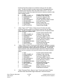
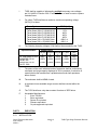
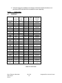
1. Page 33 12 11-2. Add the following table following Paragraph 2.02.B:
Nominal Pipe
Diameter, in.
Maximum
Flowrate, gpm
Max. Allowable
Headloss*, feet
Backpressure
Capacity, psi
Elastomer
Material
36
11,000
3.00
0
Neoprene
30
3,750
2.00
0
Neoprene
*Maximum allowable headloss at the specified maximum flowrate.
External Layer
Elastomer
Material
EPDM
EPDM
2. Page 33 12 11-2. Delete Paragraph 2.03.
SECTION 40 91 00 – INTRUMENTATION AND CONTROL SYSTEM DEVICES
1. Page 40 91 00-8. Add the following to Paragraph 2.08.A:
4.
ABB.
2. Page 40 91 00-8. Add the following to Paragraph 2.09.A:
4.
ABB.
SECTION 40 91 10 – CONTROL PANELS
1. Page 40 91 10-2. Paragraph 1.05.A.1. Delete paragraph in its entirety and replace with the
following:
1. Acceptable Control System Manufacturers:
a. Base Bid: Kahler Automation, Fairmont, MN (507) 235-6648.
b. Alternate 5 – Alternate Control Systems Manufacturers
1)
Wunderlich-Malec, Minnetonka, MN (952) 933-3222.
2)
Instrument Control Systems, Plymouth, MN (763) 559-0568.
3)
Integrated Process Solutions, Fosston, MN (218) 435-1703.
4)
No other manufacturers will be acceptable.
Water Treatment Plant
May 20, 2011
AD2 - 7
Fairmont, Minnesota
P05194-2008-00
2. Page 40 91 10-3. Paragraph 1.05.B. Delete paragraph in its entirety and Change
Paragraph 1.05.C. to 1.05.B.
3. Page 40 91 10-6. Delete line 2.02.C.1.j. in its entirety and Change line 2.02.C.1.k. to
2.02.C.1.j.
4. Page 40 91 10-6. Delete line 2.02.D.1.j. in its entirety and Change line 2.02.D.1.k. to
2.02.D.1.j.
5. Page 40 91 10-7. Delete line 2.02.G.1.i. in its entirety and Change line 2.02.G.1.j. to
2.02.G.1.i.
6. Page 40 91 10-15. Delete Paragraph 2.03.V. AMBIENT AIR TEMPERATURE
SENSOR/TRANSMITTER in its entirety.
SECTION 40 91 11 – TELEMETRY EQUIPMENT (ALTERNATE 3)
1. In the footer on all pages in Section, Delete “40 91 10” and Replace with “40 91 11”
2. In the footer on all pages in Section, Delete “Control Panels” and Replace with “Telemetry
Equipment”
3. In the footer on all pages in Section, Delete “042911” and Replace with “052011 –
Addendum No. 2”
4. Page 40 91 11-2. Paragraph 1.05.A.1. Delete paragraph in its entirety and replace with the
following:
1. Acceptable Control System Manufacturers:
a. Base Bid: Kahler Automation, Fairmont, MN (507) 235-6648.
b. Alternate 5 – Alternate Control Systems Manufacturers
1) Wunderlich-Malec, Minnetonka, MN (952) 933-3222.
2) Instrument Control Systems, Plymouth, MN (763) 559-0568.
3) Integrated Process Solutions, Fosston, MN (218) 435-1703.
4) No other manufacturers will be acceptable.
5. Page 40 91 11-2. Paragraph 1.05.A.2. Delete paragraph in its entirety and Change
Paragraph 1.05.A.3 to 1.05.A.2.
6. Page 40 91 11-2. Paragraph 1.05.B. Delete paragraph in its entirety and Change
Paragraph 1.05.C. to 1.05.B.
SECTION 40 91 16 – PROCESS METERS
1.
Page 40 91 16-5. Add the following to Paragraph 2.05.A:
3.
Water Treatment Plant
May 20, 2011
Steel-Mass Model 640S by Sierra Instruments.
AD2 - 8
Fairmont, Minnesota
P05194-2008-00
SECTION 41 52 00 – Lime Handling and Storage System
1.
Page 41 52 00-1. Add the following to Paragraph 1.02.B:
4.
Chemco Systems.
SECTION 43 11 23 – GAS HANDLING BLOWERS
1.
Page 43 11 23-2. Add the following to Paragraph 1.03.A:
1.
2.
or Kaeser Compressors.
Page 43 11 23-2. Add the following to Paragraph 1.03.B:
1.
or Kaeser Compressors.
SECTION 46 33 13 – SODIUM HYPOCHLORITE GENERATING EQUIPMENT
1. Page 46 33 13-13. Add the following text to Paragraph 2.04.A.6:
i.
OSHGS Supplier shall be responsible for providing Type 304
stainless steel Schedule 40 salt unloading pipe, including
connection to the brine generation vessel, and three (3) adjacent
long radius 90 degree pipe sweeps. Contractor shall supply all
remaining salt unloading pipe, including fill connection and
horizontal straight pipe run. Supplier provided pipe sweeps will
connect with Contractor provided pipe run as shown on the
Project Drawings. Contractor to confirm and coordinate
connection type.
SECTION 46 33 33 – POLYMER BLENDING AND FEED EQUIPMENT
1.
Page 46 33 33-4. Add the following to Paragraph 2.02.A:
3.
Enpro Technologies.
SECTION 46 36 33 – DRY CHEMICAL VOLUMETRIC FEED EQUIPMENT
1. Page 46 36 33-2. Add the following to Paragraph 2.02.A:
4.
Enpro Technologies.
SECTION 46 51 21 – AERATION DIFFUSERS
1. Page 46 51 21-3. Add the following to Paragraph 2.01.A:
3.
4.
Water Treatment Plant
May 20, 2011
SSI Aeration, Inc.
Environmental Dynamics International (EDI).
AD2 - 9
Fairmont, Minnesota
P05194-2008-00
VOLUME 4 OF 4 - ABATEMENT DOCUMENTS
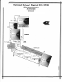
1. Revise the BUDD ELEMENTARY SCHOOL ASBESTOS REMOVAL DOCUMENTS
A. Division 1, Section 01013, Paragraph 1.2-C
1. Add: All asbestos air monitoring & air sample analysis for this project will be the
responsibility of the asbestos abatement contractor.
B. Division 1, Section 01013, Paragraph 1.2-C, Phase #2-Ground Level 1958 Addition
1. Add: Areas included in Phase #2 are Rooms 304, 307, 308, Restrooms, Chapter 1,
Speech, offices and hallways. Also included in this Phase is the hallway adjacent to
the Boiler Room. No work is required in the Music Room.
2. Also included in this phase is the removal and disposal of the boiler room fire door
and two sinks in Room 305.
C. Division 1, Section 01013, Paragraph 1.2-C, Phase #3- 1958 Window Caulk Abatement
1. Add: Included in Phase #3 is the removal and disposal of all window caulk and
glazing from the South Gym window systems.
D. Division 1, Section 01013, Paragraph 1.2-C, Phase #5- First Floor of 1950 Building
1. Delete: Delete the Stage Area from this phase (first paragraph, last sentence).
E. Drawings
1. Add: Include the attached WM Budd School 1st & 2nd Floor Plans and WM Budd
School Lower Level & Basement Plan
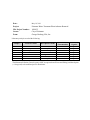
2. Revise the WATER TREATMENT PLANT ASBESTOS REMOVAL DOCUMENTS
A. Add the attached Fairmont Water Treatment Plant Lead Paint Sample Results
document.
CHANGES TO DRAWINGS
Drawing C18
1. Add Note: The GeoWeb Retaining shall be designed by the GeoWeb manufacturer and
constructed in accordance with the GeoWeb manufacturer's recommended details.
Refer to Drawing C26
1. Sanitary sewer manhole detail note 11. Internal manhole seals for S-1, S-2, S-3, and S-4
will be provided and installed by others. Contractor shall notify owner when complete so
manhole seal provider can be contacted for installation.
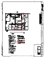
Drawing A11
1. Delete original drawing A11 dated April 2011 and replace with the attached Drawing A11,
Revision No. 1, dated May 20, 2011.
A. Dimensional change on the north wall of Reclamation Basin 2.
Drawing A19
1. The W1 windows in Control Room 305 shall be a 60 minute hollow metal frame with GL-8
glazing
2. The W8 window in Laboratory 304 shall be a 60 minute hollow metal frame with GL-8
glazing
Water Treatment Plant
May 20, 2011
AD2 - 10
Fairmont, Minnesota
P05194-2008-00
3. All W1 windows in Lunch Room 302 and Filter Operations Corridor 326 (GAC and
Conventional Filter Room) shall be window type W3.
4. All W1 windows in Stair "A" shall be window type W2.
Drawing A20
1. The W1 windows in Office 309 shall be a 60 minute hollow metal frame with GL-8 glazing
2. All W1 windows in the Solids Contact Softening Basin Room shall be window type W3.
3. All W1 windows in Stair "A" shall be window type W2.
Drawing A22
1. The W3 windows in the museum shall be non-operable
Drawing A40
1. Window types W1, W2, W3, W4, W6, and W7 shall be aluminum framing
A. Exception: W1 windows in Control Room 305 and office 309 shall be hollow metal as
noted above.
Drawing A41
1. Window types W9, W10, W11, W12, W13, W14 and W15 shall be aluminum framing
Drawing S01
1. Delete original drawing S01 dated April 2011 and replace with the attached Drawing S01,
Revision No. 1, dated May 20, 2011.
A. Dimensional change on the north wall of Reclamation Basin 2.
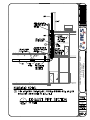
Drawing AD2-1
1. Add the attached Drawing AD2-1, dated May 20, 2011.
A. Generator exhaust pipe riser section.
Drawing M10
1. Add Note: At the cold water main to the water closet group in room 311 and 312 provide
and install a water-hammer arrester sized in accordance with the manufacturer’s
instructions.
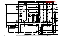
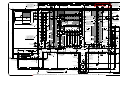
Drawing M11
1. Delete original drawing M11 dated April 2011 and replace with the attached Drawing M11,
Revision No. 2, dated May 20, 2011.
A. Compressed air extension to three (3) dry chemical feed systems.
Water Treatment Plant
May 20, 2011
AD2 - 11
Fairmont, Minnesota
P05194-2008-00
Drawing M18
1. Add Note: Exhaust fan EF-2 backwash interlock - Install a relay at the process backwash
blower motor to interlock fan operation with the backwash cycle. Provide a time clock to
provide an additional 20 minutes (adjustable) of fan operation after the backwash blower is
shutoff.
Drawing E02
1. Change Numbered Note 3 to read: Furnish and install four (4) Schedule 80 PVC conduits
with nylon pull cord. Conduits shall include one 4-inch conduit for telephone, one 2-inch
conduit for CATV, one 2-inch conduit for internet, and one 2-inch conduit for fiber optic. At
the property line furnish and install two handholes per detail on sheet E53. Route each
conduit between the handholes at the property line and the server room. Coordinate exact
location with service providers.
Drawing E04
1. Add circuit 7025 to SPU-1 control panel.
2. Add two dedicated duplex, GFI outlets for dehumidifiers at 48” near SPU-1 and fed from
PP11-16 and PP11-18 with 2-1/C-#12+Gnd-3/4” each. See Sheet M04 for exact locations.
Drawing E05
1. Add circuit 7026 to SPU-2 control panel.
2. Add three dedicated duplex, GFI outlets for dehumidifiers at 48”. One shall be located in
the north end of the corridor and fed from PP11-20, one shall be located at the east end of
the corridor and fed from PP11-22, and one shall be located at the south end of Stair A and
fed from PP11-24, with 2-1/C-#12+Gnd-3/4” each. See Sheet M04 for exact locations.
Drawing E06
1. Relocate the north UH-2 in the generator room to the adjacent storage room.
2. Add 2-1/C-#12+Gnd-3/4” from PP41 to the gas detection panel at the northeast corner of
the garage. See Sheet M17 for exact location.
Drawing E07
1. Add 2-1/C-#12+Gnd-3/4” from PP32 to the gas detection panel at the northwest corner of
the chemical unloading garage. See Sheet M16 for exact location.
2. Add to Numbered Note 7: Route 2-1/C-#12+GND-3/4” from each control station to PP32.
Drawing E08
1. Add four dedicated duplex, GFI outlets for dehumidifiers at 48”. One shall be located in the
north end of the corridor 109 and fed from PP11-26, one shall be located at the south end of
the corridor 109 and fed from PP11-28, one shall be located near Filter Press Feed Pump 2
Water Treatment Plant
May 20, 2011
AD2 - 12
Fairmont, Minnesota
P05194-2008-00
and fed from PP11-30, and one shall be located near Filter Press Feed Pump 4 and fed
from PP11-32, with 2-1/C-#12+Gnd-3/4” each. See Sheet M06 for exact locations.
Drawing E09
1. Add eight dedicated duplex, GFI outlets for dehumidifiers at 48”. One shall be located in
electrical room 110 and fed from PP22-8, one shall be located near CU-1 and fed from
PP22-10, one shall be located on the east end of the filter pipe gallery 129 and fed from
PP22-16, one shall be located in the north end of corridor 131 and fed from PP22-18, one
shall be located in the south end of corridor 131 and fed from PP22-34, two shall be in the
west end of corridor 127 and fed from PP22-12 and PP22-24, one shall be located in the
east end of corridor 127 and fed from PP22-14, with 2-1/C-#12+Gnd-3/4” each. See Sheet
M05 and M06 for exact locations.
2. Change the feeder for CU-1 to #10AWG
Drawing E10
1. Add two dedicated duplex, GFI outlets for dehumidifiers at 48”. Both shall be located in the
south end of higher service pump room 111 and fed from PP22-20 and PP22-22, with 2-1/C#12+Gnd-3/4” each. See Sheet M05 for exact locations.
2. Delete the telephone termination cabinet in electrical room 112.
3. Add circuit 7027 to SPU-3 control panel.
Drawing E11
1. Change the numbered notes for MAU-2 from 10 and 11 to 11 and 12, respectively.
2. Add 2-1/C-#12+Gnd-3/4” from the 120V disconnect for MAU-2 and MAU-3 to the associated
control panel. See Sheet M20 for MAU control panel locations.
3. Delete roof mounted outlet near EF-7
Drawing E12
1. Add to numbered note 12: “See sheet M25 for VFD mounting locations.
2. Delete the disconnect and power source for air dryer AD-1
3. Add a 30A, 480V, 3P, NEMA 1, HD, NF disconnect for AD-1 and route 3-1/C-#10-3/4” to
DP1.
Drawing E13
1. Add four dedicated duplex, GFI outlets for dehumidifiers at 48”. One shall be located in the
west end of the corridor 325 and fed from PP22-32, one shall be located at the east end of
the corridor 325 and fed from PP22-30, one shall be located at the east end of the filter
operations corridor and fed from PP22-28, and one shall be located at north end of Stair A
and fed from PP22-26, with 2-1/C-#12+Gnd-3/4” each. See Sheet M09 for exact locations.
2. Delete the outlet near EF-3.
Water Treatment Plant
May 20, 2011
AD2 - 13
Fairmont, Minnesota
P05194-2008-00
Drawing E14
1.
2.
3.
4.
5.
6.
7.
8.
Added CATV, voice, data and SCADA jacks.
Revised outlet locations and heights
Deleted roof-mounted outlets.
Added connections to exhaust fan EF-4.
Added alarm circuits to AHU-1.
Deleted the telephone cabinet in the server room.
Added CUH-8 connections.
Delete Drawing E14, Revision 0, dated April 29, 2011 and Replace with attached Drawing
E14, Revision No. 1, dated May 19, 2011.
Drawing E15
1.
2.
3.
4.
Add circuit 7035 to Sump Pump SPU-4 pump power disconnect.
Add circuit 7028 to Sump Pump SPU-4 control panel.
Add wall-mounted fiber optic patch panel next to RWCP-01.
Add two 10kW, 480V, 3PH electric unit heaters with integral thermostat, disconnect switch
and mounting hardware. Berko HUHAA, or equal. See one-line diagram for circuit
numbers. Install one in the deep intake side and one in the shallow intake side.
Drawing E16
1. Change sample pump tag SP2715 to SP5031.
2. Delete sample pumps SP5941 and SP5931 and relocate to Sheet E20.
Drawing E18
1. Add power for the fuel tank level electronics and fill box. Route 2-1/C-#12+Gnd-3/4” to
PP41. Connect “Tank Full” indicating light at fill box to fuel tank level electronics.
Drawing E20
1. Change the tag PCV5114 to PMV5114 and add circuit 7040.
2. Change the tag PCV5214 to PMV5214 and add circuit 7041.
3. Change the tag PCV5314 to PMV5314 and add circuit 7042.
4. Change the tag PCV5414 to PMV5414 and add circuit 7043.
5. Change the tag PCV5514 to PMV5514 and add circuit 7045.
6. Change the tag PCV5614 to PMV5614 and add circuit 7046.
7. Change the tag PCV5714 to PMV5714 and add circuit 7047.
8. Change the tag PCV5814 to PMV5814 and add circuit 7048.
9. Change the tag PCV5412 to PMV5412
10. Add SP5931 to the southeast corner of the filter pipe gallery and SP5941 to the northeast
corner of the filter pipe gallery.
Drawing E21
1.
2.
3.
4.
Add tag RSP6214 to the Reclaim Basin No. 1 Sludge Pump.
Add tag RSP6209 to the Reclaim Basin No. 1 Recycle Pump.
Add tag RSP6309 to the Reclaim Basin No. 2 Recycle Pump.
Add tag RSP6314 to the Reclaim Basin No. 2 Sludge Pump.
Water Treatment Plant
May 20, 2011
AD2 - 14
Fairmont, Minnesota
P05194-2008-00
Drawing E22
1. Delete circuits 2001, 3002, 4002, and 5002 to MCP-01.
2. Add circuit 7017 to MCP-01.
3. Add circuit 7013 to the MDP
Drawing E25
1. Delete circuit 6267 at the Water Vending P.O.S. terminal.
2. Add circuit 7012 to the Water Vending P.O.S terminal.
Drawing E26
1. Delete circuit 1595 to VCP2010 and 1635 to VCP2015.
2. Add circuit 7005 to VCP2010 and 7006 to VCP2015.
3. Add tag ECV2011 to the electric diverter valve.
Drawing E27
1. Delete circuit 4002 to FCP-01 and 5002 to FCP-02.
2. Add circuit 7016 to FCP-01 and 7018 to FCP-02.
Drawing E28
1. Delete circuit 1521 to VCP2020.
2. Add circuit 7007 to VCP2020.
3. Add tag MXR3420 to LSHB No.1 Mixer.
Drawing E29
1. Delete circuit 1551 to VCP2040.
2. Add circuit 7008 to VCP2040.
3. Add tag MXR3520 to LSHB No.2 Mixer.
Drawing E30
1. Add circuit 7002 to VCP2705.
Drawing E31
1. Delete circuit 1486 to VCP3601, circuit 1508 to VCP3602, circuit 1667 to VCP2300, and
circuit 3002 to CCP-01.
2. Add circuit 7004 to VCP3601, circuit 7005 to VCP3602, circuit 7010 to VCP2300, circuit
7015 to CCP-01.
Drawing E32
1. Change the bus bracing to 65,000A RMS SYM.
2. Change the location of the power monitor to monitor power downstream of the transfer
switch.
Water Treatment Plant
May 20, 2011
AD2 - 15
Fairmont, Minnesota
P05194-2008-00
Drawing E33
1. Add two N.O. contacts to the blower VFD that close when the blower is running. Contacts
shall be used for exhaust fan interlock.
2. Change the exhaust fan tags to EF-11 and EF-12.
Drawing E45
1. Add two N.O. contacts to the RWIS blower VFD that close when the blower is running.
Contacts shall be used for exhaust fan interlock.
Drawing E47
1. Add the transfer fans to the HVAC starter schematic.
Drawing E50
1. Added panel PPUPS
2. Delete Drawing E50, Revision 0, dated April 29, 2011 and Replace with attached Drawing
E50, Revision No. 1, dated May 19, 2011.
Drawing E51
1. Add fixture Type U: Fluorescent Wrap, Lithonia #CA-2-32-MVOLT-GEB10RS, 2-32-T83500 DEG K.
Drawing E60
1. Add attached Drawing E60, Revision 0, dated May 19, 2011.
Drawing E61
1. Add attached Drawing E61, Revision 0, dated May 19, 2011.
Drawing E62
1. Add attached Drawing E62, Revision 0, dated May 19, 2011.
Drawing E63
1. Add attached Drawing E63, Revision 0, dated May 19, 2011.
Drawing EC05
1. Add the following Digital Inputs to Rack 0, Slot 6:
a. Supply Fan Fail
b. Discharge Air Temp Fail
c. Freeze-stat Shutdown
d. Sump Pump SPU-1 High Level
e. Sump Pump SPU-2 High Level
f. Sump Pump SPU-3 High Level
Water Treatment Plant
May 20, 2011
AD2 - 16
Fairmont, Minnesota
P05194-2008-00
Drawing EC13
1. Delete Drawing EC13, Revision No. 1, dated 5-11-11 and Replace with the attached
Drawing EC13, Revision No. 2, dated 5-18-11.
Drawing EC14
1. Delete Drawing EC14, Revision No. 1, dated 5-11-11 and Replace with the attached
Drawing EC14, Revision No. 2, dated 5-18-11.
Drawing EC17
1. Delete Drawing EC17, Revision No. 1, dated 5-11-11 and Replace with the attached
Drawing EC17, Revision No. 2, dated 5-18-11.
Drawing EC18
1. Delete Drawing EC18, Revision No. 1, dated 5-11-11 and Replace with the attached
Drawing EC18, Revision No. 2, dated 5-18-11.
Drawing EC20
1. Add the following Digital Input to Rack 0, Slot 4:
a. Sump Pump SPU-4 High Level
CLARIFICATIONS
1. Product selections shall be from the manufactures full selection of finishes.
2. The base materials specified as MnDOT Class 5 shall be aggregate material complying with
MnDOT specifications.
3. Where gypsum board is specified on walls with window and/or door openings, provide
painted gypsum board returns at the head, jambs, and sill.
ATTACHMENT LIST TO THIS ADDENDUM
1. Cable and Conduit Schedule consisting of 3 pages.
2. 00 45 14 – Subcontractor Qualification Forms.
3. 08 44 13 – Glazed Aluminum Curtain Walls.
4. 11 85 20 – Integrated Access Control & Security Camera Systems.
5. 11 85 21 – Door Intercom System.
6. 26 43 13 – TVSS-Type Surge Protective Devices.
7. 28 13 00 – Integrated Door Access Control.
8. WM Budd School 1st & 2nd Floor Plans.
9. WM Budd School Lower Level & Basement Plan.
10. Fairmont Water Treatment Plant Lead Paint Sample Results.
11. Drawing A11, Revision No. 1, Dated 5-20-11.
12. Drawing S01, Revision No. 1, Dated 5-20-11.
13. Drawing AD2-1, Revision No. 2, Dated 5-20-11.
14. Drawing M11, Revision No. 2, Dated 5-20-11.
15. Revised Drawing E14.
Water Treatment Plant
May 20, 2011
AD2 - 17
Fairmont, Minnesota
P05194-2008-00
16. Revised Drawing E50.
17. Drawing E60.
18. Drawing E61.
19. Drawing E62.
20. Drawing E63.
21. Drawing EC13, Revision No. 2, Dated 5-18-11.
22. Drawing EC14, Revision No. 2, Dated 5-18-11.
23. Drawing EC17, Revision No. 2, Dated 5-18-11.
24. Drawing EC18, Revision No. 2, Dated 5-18-11.
I hereby certify that this plan, specification, or report was prepared by me or under my direct
supervision, and that I am duly registered as a Professional Engineer under the laws of the
State of Minnesota.
Jason Kosmatka, PE
Registration Number 45841
May 20, 2011
END OF ADDENDUM NO. 2
Water Treatment Plant
May 20, 2011
AD2 - 18
Fairmont, Minnesota
P05194-2008-00
Fairmont, Minnesota
Water Treatment Plant Improvements
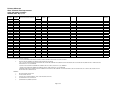
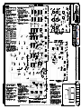
CABLE AND CONDUIT SCHEDULE
ADDENDA ITEMS - May 19, 2011
CIRCUIT
NUMBER
CONDUIT
NUMBER
CONDUIT
SIZE
VOLTS &
PHASE
7000
C7000
FROM
VIA
TO
1-CAT6
1"
DATA
NWP-01
C7000
VCP2210 RECARBONATION-PRESSURE FEED PANEL 1
7001
7002
C7001
1-CAT6
1"
DATA
NWP-01
C7001
VCP2220 RECARBONATION-PRESSURE FEED PANEL 2
C7002
1-CAT6
1"
DATA
NWP-01
C7002
VCP2705 AMMONIA FEED SYSTEM PANEL
7003
C7003
1-CAT6
1"
DATA
NWP-01
C7003
VCP3601 FILTER PRESS CONTROL PANEL 1
7004
C7004
1-CAT6
1"
DATA
NWP-01
C7004
VCP3602 FILTER PRESS CONTROL PANEL 2
7005
C7005
1-CAT6
1"
DATA
NWP-01
C7005
LIME SILO NO. 1 CONTROL PANEL
7006
C7006
1-CAT6
1"
DATA
NWP-01
C7006
LIME SILO NO. 2 CONTROL PANEL
7007
C7007
1-CAT6
1"
DATA
NWP-01
C7007
LIME SLAKER NO. 1 CONTROL PANEL
7008
C7008
1-CAT6
1"
DATA
C7008
LIME SLAKER NO. 2 CONTROL PANEL
7009
C7009
7010
C7010
1-CAT6
1"
DATA
NWP-01
C7010
OSHGS CONTROL ENCLOSURE
7011
C7011
1-CAT6
1"
DATA
NWP-01
C7011
UPS
7012
C7012
1-CAT6
1"
DATA
NWP-01
C7012
WATER VENDING P.O.S. TERMINAL
7013
C7013
1-CAT6
1"
DATA
NWP-01
C7013
MAIN DISTRIBUTION PANEL POWER MONITOR
7014
C7014
7015
C7015
1-CAT6
1"
DATA
NWP-01
C7015
CHEMICAL CONTROL PANEL CCP-01
7016
C7016
1-CAT6
1"
DATA
NWP-01
C7016
FILTER CONTROL PANEL FCP-01
7017
C7017
1-CAT6
1"
DATA
NWP-01
C7017
MASTER CONTROL PANEL MCP-01
7018
C7018
1-CAT6
1"
DATA
NWP-01
C7018
FILTER CONTROL PANEL FCP-02
7019
C7019
1-CAT6
1"
DATA
NWP-01
C7019
WTP POLLING MASTER
7020
C7020
7021
C7021
7022
C7022
7023
C7023
7024
C7024
7025
C7025
2-1/C-#14
3/4"
CONTROL SUMP PUMP SPU-1
C7025
PANEL MCP-01
7026
C7026
2-1/C-#14
3/4"
CONTROL SUMP PUMP SPU-2
C7026
PANEL MCP-01
7027
C7027
2-1/C-#14
3/4"
CONTROL SUMP PUMP SPU-3
C7027
PANEL MCP-01
7028
C7028
2-1/C-#14
3/4"
CONTROL SUMP PUMP SPU-4
C7028
PANEL RWCP-01
7029
C7029
7030
C7030
4-1/C-#14
3/4"
CONTROL AIR HANDLING UNIT AHU-1
C7030
PANEL MCP-01
7031
C7031
4-1/C-#14
3/4"
CONTROL AIR HANDLING UNIT AHU-2
C7031
PANEL MCP-01
7032
C7032
7033
C7033
7034
C7034
CONDUCTOR QUANTITY AND SIZE
Page 1 of 3
REMARKS
Fairmont, Minnesota
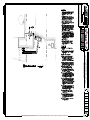
Water Treatment Plant Improvements
CABLE AND CONDUIT SCHEDULE
ADDENDA ITEMS - May 19, 2011
CIRCUIT
NUMBER
CONDUIT
NUMBER
CONDUIT
SIZE
VOLTS &
PHASE
7035
C7035
3-1/C-#12+GND
3/4"
480-3
7036
7037
C7036
4-1/C-#4+GND
3/4"
C7037
4-1/C-#4+GND
3/4"
7038
C7038
7039
C7039
CONDUCTOR QUANTITY AND SIZE
FROM
VIA
TO
RWIS MCC
C7035
SUMP PUMP SPU-4
120/208-3
PP32
C7036
UNINTERRUPTIBLE POWER SUPPLY (UPS)
120/208-3
UPS
C7037
UPS PANELBOARD
7040
C7040
2-2/C-#16 SHIELDED
3/4"
SIGNAL
PANEL FCP-01
C7040
PMV5114 CONVENTIONAL FILTER 1 FILTER-WASTE VALVE
7041
C7041
2-2/C-#16 SHIELDED
3/4"
SIGNAL
PANEL FCP-01
C7041
PMV5214 CONVENTIONAL FILTER 2 FILTER-WASTE VALVE
7042
C7042
2-2/C-#16 SHIELDED
3/4"
SIGNAL
PANEL FCP-01
C7042
PMV5314 CONVENTIONAL FILTER 3 FILTER-WASTE VALVE
7043
C7043
2-2/C-#16 SHIELDED
3/4"
SIGNAL
PANEL FCP-01
C7043
PMV5414 CONVENTIONAL FILTER 4 FILTER-WASTE VALVE
7044
C7044
7045
C7045
2-2/C-#16 SHIELDED
3/4"
SIGNAL
PANEL FCP-02
C7045
PMV5514 GAC FILTER 1 FILTER-WASTE VALVE
7046
C7046
2-2/C-#16 SHIELDED
3/4"
SIGNAL
PANEL FCP-02
C7046
PMV5614 GAC FILTER 2 FILTER-WASTE VALVE
7047
C7047
2-2/C-#16 SHIELDED
3/4"
SIGNAL
PANEL FCP-02
C7047
PMV5714 GAC FILTER 3 FILTER-WASTE VALVE
7048
C7048
2-2/C-#16 SHIELDED
3/4"
SIGNAL
PANEL FCP-02
C7048
PMV5814 GAC FILTER 4 FILTER-WASTE VALVE
7049
C7049
7050
C7050
1-1/C-#6 BARE-STRANDED GND
3/4"
GND
MDP GROUND BUS
C7050
TELEPHONE BOARD
7051
C7051
1-1/C-#6 BARE-STRANDED GND
3/4"
GND
MDP GROUND BUS
C7050
NWP-01
7052
C7052
7053
C7053
7054
C7054
7055
C7055
7056
C7056
7057
C7057
7058
C7058
7059
C7059
7060
C7060
7061
C7061
7062
C7062
7063
C7063
7064
C7064
7065
C7065
7066
C7066
7067
C7067
7068
C7068
7069
C7069
7070
C7070
7071
C7071
7072
C7072
7073
C7073
7074
C7074
Page 2 of 3
REMARKS
Fairmont, Minnesota
Water Treatment Plant Improvements
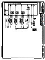
CABLE AND CONDUIT SCHEDULE
ADDENDA ITEMS - May 19, 2011
CIRCUIT
NUMBER
CONDUIT
NUMBER
7075
C7075
7076
C7076
7077
C7077
7078
C7078
7079
C7079
7080
C7080
7081
C7081
7082
C7082
7083
C7083
7084
C7084
7085
C7085
7086
C7086
7087
C7087
7088
C7088
7089
C7089
7090
C7090
7091
C7091
7092
C7092
7093
C7093
7094
C7094
7095
C7095
7096
C7096
7097
C7097
7098
C7098
7099
C7099
CONDUCTOR QUANTITY AND SIZE
CONDUIT
SIZE
VOLTS &
PHASE
FROM
VIA
TO
GENERAL NOTES FOR CABLE AND CONDUIT SCHEDULE:
1.
2.
DO NOT ROUTE CABLES FOR DIVISION 15 HVAC CONTROL SYSTEM IN THE DIVISION 16 CONDUIT SYSTEM.
CIRCUITS MAY BE COMBINED IN COMMON CONDUITS PER THE FOLLOWING:
a. UP TO FOUR CONSTANT-SPEED MOTOR FEEDER CIRCUITS MAY BE COMBINED IN A COMMON CONDUIT. INCREASE CONDUCTOR SIZES AS REQUIRED PER N.E.C. DERATION RULES.
LIMIT CONDUIT FILL TO 30% MAXIMUM.
b. CONTROL CIRCUITS MAY BE COMBINED IN COMMON CONDUITS. LIMIT CONDUIT FILL TO 30% MAXIMUM.
c. SIGNAL CIRCUITS MAY BE COMBINED IN COMMON CONDUITS. LIMIT CONDUIT FILL TO 30% MAXIMUM.
d. VARIABLE-SPEED MOTOR FEEDER CIRCUITS POWERED BY VFDS MAY NOT BE COMBINED. PROVIDE SEPARATE CONDUIT FOR EACH CIRCUIT. CONTROL CIRCUITS MAY NOT BE
ROUTED WITH VFD POWER CIRCUITS.
REMARKS:
1.
INCLUDES SPARE CONDUCTORS.
2.
VIA DISCONNECT SWITCH.
3.
CONDUIT FOR FUTURE EQUIPMENT. STUB UP AS INDICATED ON PLANS.
4.
COORDINATE WITH TC CONTRACTOR
5.
CONFIRM WITH EQUIPMENT SUPPLIER
Page 3 of 3
REMARKS
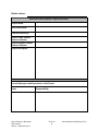
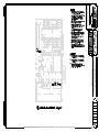
SECTION 00 45 14
SUBCONTRACTOR QUALIFICATIONS FORMS
Bidder’s Name:
Electrical Subcontractor Information
Full Legal Name:
Organization Type:
State of Incorporation:
Address for Notices:
Contact Name:
Contact Number:
Years in Business:
Dollar Value of
Water/Wastewater
Treatment Plant
Construction Work in Past
10 Years:
Description of Work that
will be Self-Performed:
City of Fairmont, Minnesota
WTP Project
052011 – Addendum No. 2
00 45 14
1
Subcontractor Qualifications Form
Bidder’s Name:
Electrical Subcontractor Project Reference
Project Name:
Year Constructed:
Contract Amount ($):
Project Owner Contact
Name and Number
Project Engineer Contact
Name and Number
Project Description
Current Employees with Experience on this Project
Name
City of Fairmont, Minnesota
WTP Project
052011 – Addendum No. 2
Responsibility
00 45 14
2
Subcontractor Qualifications Form
Bidder’s Name:
Mechanical Subcontractor Information
Full Legal Name:
Organization Type:
State of Incorporation:
Address for Notices:
Contact Name:
Contact Number:
Years in Business:
Dollar Value of
Water/Wastewater
Treatment Plant
Construction Work in Past
10 Years:
Description of Work that
will be Self-Performed:
City of Fairmont, Minnesota
WTP Project
052011 – Addendum No. 2
00 45 14
3
Subcontractor Qualifications Form
Bidder’s Name:
Mechanical Subcontractor Project Reference
Project Name:
Year Constructed:
Contract Amount ($):
Project Owner Contact
Name and Number
Project Engineer Contact
Name and Number
Project Description
Current Employees with Experience on this Project
Name
City of Fairmont, Minnesota
WTP Project
052011 – Addendum No. 2
Responsibility
00 45 14
4
Subcontractor Qualifications Form
DIVISION 08 – OPENINGS
SECTION 08 44 13 – GLAZED ALUMINUM CURTAIN WALLS
PART 1
GENERAL
1.01 SECTION INCLUDES
A. Aluminum-framed curtain wall with vision glazing.
1.02 REFERENCE STANDARDS
A. AAMA CW-10 - Care and Handling of Architectural Aluminum From Shop to Site;
American Architectural Manufacturers Association.
B. AAMA 611 - Voluntary Specification for Anodized Architectural Aluminum; American
Architectural Manufacturers Association.
C. ASCE 7 - Minimum Design Loads for Buildings and Other Structures; American
Society of Civil Engineers.
D. ASTM B 221 - Standard Specification for Aluminum and Aluminum-Alloy Extruded
Bars, Rods, Wire, Profiles, and Tubes.
E. ASTM B 221M - Standard Specification for Aluminum and Aluminum-Alloy Extruded
Bars, Rods, Wire, Profiles, and Tubes Metric.
F.
ASTM E 283 - Standard Test Method for Determining the Rate of Air Leakage Through
Exterior Windows, Curtain Walls, and Doors Under Specified Pressure Differences
Across the Specimen.
1.03 ADMINISTRATIVE REQUIREMENTS
A. Coordinate with installation of other components that comprise the exterior enclosure.
B. Preinstallation Meeting: Conduct a preinstallation meeting one week before starting
work of this section; require attendance by all affected installers.
1.04 SUBMITTALS
A. See Section 01 33 00 - Submittal Procedures.
B. Product Data: Provide component dimensions, describe components within assembly,
anchorage and fasteners, glazing and infill, internal drainage details.
C. Shop Drawings: Indicate system dimensions, framed opening requirements and
tolerances, affected related Work, expansion and contraction joint location and details,
and field welding required.
D. Design Data: Provide framing member structural and physical characteristics and
engineering calculations, and identify dimensional limitations.
E. Warranty: Submit manufacturer warranty and ensure forms have been completed in
Owner's name and registered with manufacturer.
City of Fairmont, Minnesota
WTP Project
052011
08 44 13
1
Glazed Aluminum Curtain Walls
1.05 QUALITY ASSURANCE
A. Designer Qualifications: Design structural support framing components under direct
supervision of a Professional Structural Engineer experienced in design of this Work
and licensed at the State in which the Project is located.
B. Manufacturer and Installer: Company specializing in manufacturing aluminum glazing
systems with minimum five years of documented experience.
1.06 DELIVERY, STORAGE, AND HANDLING
A. Handle products of this section in accordance with AAMA CW-10.
B. Protect finished aluminum surfaces with wrapping. Do not use adhesive papers or
sprayed coatings that bond to aluminum when exposed to sunlight or weather.
1.07 WARRANTY
A. See Section 01 78 00 - Closeout Submittals, for additional warranty requirements.
B. Provide five year manufacturer warranty against failure of glass seal on insulating
glass units, including interpane dusting or misting. Include provision for replacement
of failed units.
C. Provide five year manufacturer warranty against excessive degradation of exterior
finish. Include provision for replacement of units with excessive fading, chalking, or
flaking.
PART 2
PRODUCTS
2.01 MANUFACTURERS
A. Basis of Design:
1. Kawneer; Product 1600 Wall System 1: www.kawneer.com.
B. Other Acceptable Manufacturers:
1. Manufacturers providing equivalent products listed in Section 08 43 13 Aluminum-Framed Storefronts.
2. Substitutions: See Section 01 60 00 - Product Requirements.
2.02 CURTAIN WALL
A. Aluminum-Framed Curtain Wall: Factory fabricated, factory finished aluminum framing
members with infill, and related flashings, anchorage and attachment devices.
1. Finish: Class I color anodized.
a. Color: Champagne.
b. Factory finish all surfaces that will be exposed in completed assemblies.
c. Touch-up surfaces cut during fabrication so that no natural aluminum is
visible in completed assemblies, including joint edges.
d. Coat concealed metal surfaces that will be in contact with cementitious
materials or dissimilar metals with bituminous paint.
2. Fabrication: Joints and corners flush, hairline, and weatherproof, accurately fitted
and secured; prepared to receive anchors; fasteners and attachments concealed
from view; reinforced as required for imposed loads.
City of Fairmont, Minnesota
WTP Project
052011
08 44 13
2
Glazed Aluminum Curtain Walls
3.
4.
Construction: Eliminate noises caused by wind and thermal movement, prevent
vibration harmonics, and prevent "stack effect" in internal spaces.
System Internal Drainage: Drain to the exterior by means of a weep drainage
network any water entering joints, condensation occurring in glazing channel, and
migrating moisture occurring within system.
B. Structural Performance Requirements: Design and size components to withstand the
following load requirements without damage or permanent set.
1. Design Wind Loads: Comply with the requirements of the International Building
code.
a. Positive Design Wind Load: 25 lbf/sq ft.
b. Negative Design Wind Load: 25 lbf/sq ft.
2. Movement: Accommodate the following movement without damage to
components or deterioration of seals:
a. Expansion and contraction caused by 180 degrees F surface temperature.
b. Expansion and contraction caused by cycling temperature range of 170
degrees F over a 12 hour period.
c. Movement of curtain wall relative to perimeter framing.
d. Deflection of structural support framing, under permanent and dynamic loads.
2.03 COMPONENTS
A. Aluminum Framing Members: Tubular aluminum sections, thermally broken with
interior section insulated from exterior, drainage holes and internal weep drainage
system.
2.04 MATERIALS
A. Extruded Aluminum: ASTM B 221 (ASTM B 221M).
B. Glazing: As specified in Section 08 80 00.
C. Glazing Gaskets: Type to suit application to achieve weather, moisture, and air
infiltration requirements.
D. Glazing Accessories: As specified in Section 08 80 00.
2.05 FINISHES
A. Class I Color Anodized Finish: AAMA 611 AA-M12C22A42 Integrally colored anodic
coating or AAMA 612 electrolytically deposited colored anodic coating with
electrolytically deposited organic seal; not less than 0.7 mils thick.
2.06 ACCESSORIES
A. Shims: Plastic shims.
PART 3
EXECUTION
3.01 EXAMINATION
A. Verify dimensions, tolerances, and method of attachment with other work.
B. Verify that wall openings and adjoining air and vapor seal materials are ready to
receive work of this section.
City of Fairmont, Minnesota
WTP Project
052011
08 44 13
3
Glazed Aluminum Curtain Walls
C. Verify that anchorage devices have been properly installed and located.
3.02 INSTALLATION
A. Install wall system in accordance with manufacturer's instructions.
B. Attach to structure to permit sufficient adjustment to accommodate construction
tolerances and other irregularities.
C. Provide alignment attachments and shims to permanently fasten system to building
structure.
D. Align assembly plumb and level, free of warp or twist. Maintain assembly dimensional
tolerances, aligning with adjacent work.
E. Provide thermal isolation where components penetrate or disrupt building insulation.
F.
Install sill flashings. Turn up ends and edges; seal to adjacent work to form water tight
dam.
G. Coordinate attachment and seal of perimeter air and vapor barrier materials.
H. Pressure Plate Framing: Install glazing and infill panels in accordance with Section 08
80 00, using exterior dry glazing method.
I.
Touch-up minor damage to factory applied finish; replace components that cannot be
satisfactorily repaired.
3.03 TOLERANCES
A. Maximum Variation from Plumb: 0.06 inches every 3 ft non-cumulative or 0.5 inches
per 100 ft, whichever is less.
B. Maximum Misalignment of Two Adjoining Members Abutting in Plane: 1/32 inch.
C. Sealant Space Between Curtain Wall Mullions and Adjacent Construction: Maximum
of 3/4 inch and minimum of 1/4 inch.
3.04 CLEANING
A. Remove protective material from pre-finished aluminum surfaces.
B. Wash down surfaces with a solution of mild detergent in warm water, applied with soft,
clean wiping cloths. Take care to remove dirt from corners. Wipe surfaces clean.
C. Remove excess sealant by method acceptable to sealant manufacturer.
3.05 PROTECTION
A. Protect installed products from damage during subsequent construction.
END OF SECTION
City of Fairmont, Minnesota
WTP Project
052011
08 44 13
4
Glazed Aluminum Curtain Walls
DIVISION 11 – EQUIPMENT
SECTION 11 85 20 – INTEGRATED ACCESS CONTROL
AND SECURITY CAMERA SYSTEMS
PART 1
1.01
SUMMARY
A.
1.02
Section Includes (for Laboratory and Control Room):
1.
Modular and custom steel casework.
DESCRIPTION
A.
1.03
PRODUCT CATEGORY: AMERICAN DYNAMICS FIXED IP CAMERAS
The illustra 400 Series IP camera
BID SPECIFICATION
A.
The camera shall utilize the Sony IMX035 CMOS sensor.
B.
The minidome and bullet cameras shall have an integrated 3.3-12mm IR
corrected varifocal lens.
C.
The camera shall have a dome enclosure complying with IP66 weatherproofing
standards.
D.
The camera shall dome chassis shall be vandal resistant constructed of
aluminum with a polycarbonate dome bubble (illustra 400 outdoor fixed dome
and bullet only).
E.
The camera shall have a 3-axis gimbal with 360° pan 90° tilt and 180° Z-rotation
for easy and accurate positioning.
F.
The camera shall be surface mountable with optional pendant mount or wall
mount.
G.
The camera shall be H.264 (MPEG4, Part 10) compliant.
H.
The camera shall have dual standard compression support with simultaneous
streaming of both H.264 and MJPEG formats.
I.
The camera shall have multi-streaming support of up to 8 non-identical
concurrent streams (different frame rate, bit rate, resolution, quality and
compression format).
J.
The camera‘s bit rate control shall be selectable between constant bit rate and
variable constrained variable bit rate.
K.
The camera shall have Real Time Streaming Protocol (RTSP) support allowing
for compatibility with media players such as Windows Media Player, Apple
QuickTime, VLC Player and others.
L.
The camera shall output at a maximum resolution of 896(H) x 720(V) pixels at a
maximum frame rate of 30 frames per second (FPS).
City of Fairmont, Minnesota
WTP Project
052011
11 85 20
1
Integrated Access Control
And Security Camera Systems
M.
It shall be possible to program the camera to output a variety of lower resolution
images, i.e., CIF and D1 30 FPS.
N.
The camera shall provide 5 level settings for quality of H.264 compression.
O.
The camera shall support a HTTP and RTSP/RTP network protocols.
P.
The cameras shall feature motion detection with a minimum of 500 independent
detection zones.
Q.
The camera shall feature automatic exposure, automatic white balance, shutter
speed control, 50/60Hz selectable flicker control, programmable brightness,
saturation, gamma, sharpness, windowing and decimation, simultaneous delivery
of full-field view.
R.
The camera shall incorporate necessary algorithms and circuits to detect motion
in low light with clarity.
S.
The camera shall support a minimum illumination of 0.2 Lux @ F1.2 in color
mode.
T.
The camera shall support an IR sensitive minimum illumination of 0.01 Lux in
B/W mode.
U.
The camera‘s primary power source shall be Power over Ethernet (PoE)
complying with the IEEE 802.3af standard.
V.
The camera shall have IR illuminators capable of illumination up to 54 feet
powered by PoE (802.3af).
W.
The camera shall have the alternative option to be powered from between a 12V
DC or 24V AC power source providing at least 5W of power.
X.
The camera‘s operating ambient temperature shall be -40°C (-40°F) to 50ºC
(122ºF) for warm start conditions (for outdoor fixed dome and bullet models).
Y.
The camera shall be FCC Part 15, Class A and CE compliant.
Z.
The camera shall have the ability to directly export snapshot images in JPEG
form and video clips via email, FTP, Network storage and on board SDHC card.
AA.
The camera shall be able to store and utilize the user name and password of the
SMTP server to enable protected email export.
BB.
The camera shall be able to record to an SDHC card based on motion detection,
alarm input, or on schedule managed via the camera‘s web-based GUI.
CC.
The camera shall be able to record to a SDHC card in a circular fashion.
DD.
Recorded video on the cameras SDHC card shall be accessible via the cameras
web browser GUI.
EE.
The camera shall have the capability to provide at least 3 independent privacy
zones.
FF.
The camera shall have 48MB of buffer storage for pre and post alarm capture.
City of Fairmont, Minnesota
WTP Project
052011
11 85 20
2
Integrated Access Control
And Security Camera Systems
GG.
The camera shall have at least one alarm output and one alarm input.
HH.
The camera shall have a Linux based operating system.
II.
The camera shall have RSA-based public key cryptography with a 1024 bit
private key length.
JJ.
The camera shall support bi-directional audio in half and full duplex.
KK.
The camera shall support wide dynamic range up to 100dB with 9 quality
settings.
PART 2
PRODUCT CATEGORY: AMERICAN DYNAMICS ENVIRONMENTAL
CAMERA HOUSINGS
2.01
DESCRIPTION
A.
2.02
High quality environmental housing designed to provide an excellent barrier
against indoor and outdoor environments for most CCD cameras with fixed or
zoom lenses.
PERFORMANCE SPECIFICATIONS
A.
The camera housing must provide a unique 180 opening cover to provide full
and easy access to the camera and lens for trouble-free installation and
servicing.
B.
The maximum camera/lens combination length must be no less than 304.8 mm
(12.0 in), including connectors.
C.
The housing must have a camera platform that can be secured in any position
along the full length of the housing. This platform shall be constructed of a rigid
non-conductive material to help eliminate common grounding problems.
D.
The camera housing must be constructed of a high-impact Magnum
Polymer with a 4.8 mm (.19 in) Lexan viewing window.
E.
The camera housing will protect against water and dust intrusion and meet a
minimum of IP63 and NEMA-3R ratings. An optional sunshield must be available
to protect the entire top half of the housing from solar radiation.
F.
The housing must offer an optional thermostatically controlled pad heater and
automatically regulate its output to provide heat in the housing and maintain a
clear viewing window. The heater shall operate with either 24 VAC or 24 VDC
supply voltages.
G.
The housing must offer an optional thermostatically regulated 24 VAC blower.
H.
Two weatherproof glands must be provided on the bottom of the housing for
cable entry.
I.
The camera housing must have a light gray epoxy finish.
J.
The housing must be secured from unauthorized entries by the use of tamper
resistant screws.
City of Fairmont, Minnesota
WTP Project
052011
11 85 20
3
941
Integrated Access Control
And Security Camera Systems
2.03
K.
Optional wall or ceiling mounts must be available for the camera housing. The
mounts must have a weight load capacity of no less than 9.1 Kg (20 lbs.), and
have a light gray finish to match the camera housing. The mounts shall be
suitable for indoor or outdoor applications.
L.
The camera housing and mounts shall be an American Dynamics Illustra 400
Series.
MINIMUM PERFORMANCE SPECIFICATIONS
A.
The camera housing must meet the following requirements:
B.
Mechanical:
1.
2.
Construction:
a.
Housing:
Magnum 941 Polymer
b.
Viewing Window:
4.8 mm (.19 in) Lexan
c.
Finish: Epoxy
d.
Color: Light gray
e.
Dimensions (H x W x L):
141 x 159 x 449 mm (5.56 x 6.2 x
17.68 in)
3.
4.
Unit Weight:
a.
Without sunshield:
1.8 Kg (4.0 lbs.)
b.
With sunshield:
3.2 Kg (7.0 lbs.)
c.
Cable Entry: 2 weatherproof glands
d.
Max. Camera/Lens Length: 304.8 mm (12.0 in)
e.
Camera Mounting:
Non-metallic multi-position front to back
adjustment
5.
6.
Heater Kit:
a.
Type: Thermostatically controlled pad heater
b.
Supply Voltage:
24 VAC/VDC (12-30V)
c.
Power: 0.63 A maximum
d.
Weight:
68 g (0.15 lbs.)
7.
8.
Blower Kit:
a.
Supply Voltage:
24 VAC
C.
Environmental
1.
2.
Weatherproof Standard:
3.
Operating Temperature:
heater/blower.
D.
Regulatory
1.
CE.
E.
Warranty
1.
Minimum two years.
City of Fairmont, Minnesota
WTP Project
052011
11 85 20
4
IP63 (NEMA-3R)
-23 to 43 C (-10 to 110 F) with
Integrated Access Control
And Security Camera Systems
PART 3
PRODUCT CATEGORY: AMERICAN DYNAMICS HYBRID DIGITAL VIDEO
RECORDERS
A.
The Hybrid Digital Video Recorder (HDVR) shall have Video Management
System (VMS) software for viewing live and recorded video from analog and IP
cameras and video encoders connected to a local and wide area network. The
VMS software shall have a Client-Server based architecture that can be
configured as a standalone VMS system with the Client software running on the
server hardware and/or the Client running on any network connected TCP/IP PC
workstation. Multiple client workstations shall be capable of simultaneously
viewing live and/or recorded video from a single or multiple servers. Multiple
servers shall also be able to simultaneously provide live and/or recorded video to
a single or multiple workstation(s). Included in the cost of the software are an
unlimited number of client software applications.
B.
IP Camera and Encoder Support: The VMS software running on the HDVR shall
have an open architecture supporting IP cameras and encoders from multiple
manufacturers providing best of breed solutions from low cost entry level features
to high resolution megapixel features. A minimum of five (5) IP camera
manufacturers must be supported from leading companies such as ACTi,
Arecont Vision, Axis, IQinvision, Panasonic, Sony and Vivotek.
C.
VMS Client Server Architecture: The VMS software running on the HDVR shall
be based on a client / server architecture. A client / server architecture provides
a scalable platform, whereby each computer on a network is a client, server or
both a client/server simultaneously.
D.
VMS Client Software: A client is a computer system that accesses a (remote)
service on another computer by a TCP/IP network. The VMS Client software
displays and searches live and recorded video, audio and alarms, and
administers the VMS Server configurations.
1.
There shall be one VMS Client application that shall be installed in two
different configurations depending on the requirements. The VMS Client
shall have the same features, functions and user interface in either
configuration. The first client installation configuration is referred to as a
Local Client, meaning the client resides on the same system that is ―local‖
to the server. The second installation is referred to as a Remote Client,
meaning it is installed on a different computer that is ―remote‖ from the
server and is connected to the server through a local or wide area
network. All interaction (viewing live or recorded video and
administration) with the server shall be performed through either the Local
or Remote client.
2.
When configuring a server with full administrative privileges with either a
Local or Remote Client all administration and configurations functions
shall be identical. By having full administration and configuration features
from a Remote Client, customers and installers shall save time and
money by not being required to administer features where the server
hardware is physically located.
3.
At no time during the administration and configuration of any feature of a
server from either a Local or Remote Client shall video recording be
City of Fairmont, Minnesota
WTP Project
052011
11 85 20
5
Integrated Access Control
And Security Camera Systems
4.
5.
required to be disabled.
The VMS Client software shall operate on any of the following operating
systems:
a.
Microsoft Windows Server 2003
b.
Microsoft Windows XP (all versions)
c.
Microsoft Windows Vista (all versions)
Any combination of VMS Client applications running on any of the above
listed operating systems shall be able to connect to view and retrieve live
or recorded video from any of the HDVR Server applications running on
any of the operating systems listed in 2.01 G below.
E.
Client Browser: A Browser based Client shall have a feature to connect to a
VMS Server to display live video. The Client Browser shall display video on a
PC, Mac, Linux PC, PDA, iPhone & CEL phone using the following browsers:
1.
Internet Explorer 6, 7 or 8
2.
Firefox 2 or 3
3.
Opera 9 and above
4.
Safari 2 or 3
5.
The Client Browser shall also connect with non-Java script browsers and
shall be compliant with HTML 4.0 (www.w3.org).
F.
VMS Client on Multiple Monitors: The VMS software shall have the capability to
run multiple client applications simultaneously on one PC workstation with
multiple monitors. Up to four VGA monitors shall be configured on a single PC
workstation with one client application running on each VGA monitor. As
decompressing video is CPU-intensive, the PC workstation shall have multiple
processors, one for each VMS client application. The HP PT453A Display
Adaptor shall be used to support up to four VGA monitors. This is an NVidia
Quadro-based board that shall have been tested running the VMS Client with
VGA and DVI monitors up to 1920x1200 resolutions.
G.
VMS Server Software: A server is a computer system that provides services to
other computing systems—called clients—over a TCP/IP network. The VMS
Server software shall record and retrieve video, audio and alarm data and
provide it to the VMS Clients upon request. The VMS Server software running
on the Hybrid DVR shall operate on Microsoft Windows XP
H.
Standalone Client/Server: A client and server can simultaneously reside and
operate on one computer and communicate to each other through a TCP/IP loop
back interface. A loopback address is a special IP address (127.0.0.1) that is
designed for the client and server software to communicate with each other on
the same computer. By combining the functionality of the VMS Client and Server
software on one system, administrators can deploy both standalone and network
configurations that can scale required. The administrator shall have the added
benefit of configuring and administering the VMS server with identical features
either locally or remotely.
I.
IP Camera based Motion Detection: Motion based video recording with the VMS
server software shall be based on using the motion detection alarm (also known
as a flag) generated by the IP camera. The motion detection feature of the IP
camera shall generates an alarm whenever movement occurs in the image. The
City of Fairmont, Minnesota
WTP Project
052011
11 85 20
6
Integrated Access Control
And Security Camera Systems
VMS server software reads the alarm from the IP camera to determine if motion
occurred then records video. The benefits of using IP camera based motion
detection vs. server (host processor) based motion detection include:
1.
Reduced server processor speed requirements
2.
Reduced server memory requirements
3.
Reduced processor heat
4.
Reduced CPU processor usage
5.
Increased IP camera connectivity
6.
Increased IP camera throughput
3.02
J.
Licensing VMS Software: The VMS server software shall have a feature to
license the MAC address of the server hardware. Licensing individual IP
cameras or encoders shall not be required. Licenses the server simplifies the
installation and management of IP cameras or encoders by eliminating the need
to provide additional MAC addresses for all the individual devices (IP cameras or
encoders). If an IP camera or encoder fails to operate for any reason an
administrator shall be able to add a new IP camera or encoder to the VMS server
software without the need to obtain a new license key.
K.
The VMS server software shall run as a service. If the VMS Client software is
shut down the VMS server software service shall continue to record video and
perform all other configured functions.
L.
Installing and Updating VMS Client Software: Installing a new release of the
VMS Client software shall be easily accessed by a website download.
M.
Installing and Updating VMS Server+Client Software: New releases of the VMS
Server+Client software shall be easily accessed from a website. Download the
new VMS Server+Client Installer.exe file to a CD or USB key. Insert the CD or
USB key to VMS hardware. Run the VMS Server+Client Installer.exe from the
CD or USB key and the new VMS Server+Client software will be automatically
updated. Restart the VMS Server software.
HYBRID VIDEO MANAGEMENT SYSTEM SOFTWARE FEATURES
A.
Operating Modes: The VMS software shall have three main modes of operation
depicted by three icons. Clicking on any of these icons below shall change the
mode of operation:
1.
Live Display Mode Icon allows users the ability view live video.
2.
Search Mode Icon allows users the ability to search for recorded video.
3.
Setup Mode Icon allows Administrators and Power Users the ability
configure systems.
B.
Live Display Mode Features: A live display mode shall have features for users to
view live video. The live display mode shall have the following features to
navigate and view live video:
1.
Layout Icons – shall have features to organize the camera video view
panel in the following patterns:
a.
1 camera (full screen) layout
b.
4 camera (2 x 2) layout
City of Fairmont, Minnesota
WTP Project
052011
11 85 20
7
Integrated Access Control
And Security Camera Systems
2.
3.
4.
5.
6.
7.
8.
9.
10.
c.
9 camera (3 x 3) layout
d.
12 camera (4 x 3) layout
e.
16 camera (4 x 4) layout
f.
20 camera (5 x 4) layout
g.
30 camera (6 x 5) layout
h.
48 camera (8 x 6) layout
Navigation Tree – shall display cameras, alarms, monitor & audio icons
that are connected to the VMS server.
Navigation Pane – shall display a hierarchy of cameras, audio input and
serial port input icons organized by Cameras (cameras connected to
servers), Groups (logical grouping of cameras) and Views (Saved live
display layouts). Clicking on navigation pane bars shall switch the
navigation tree into the desired navigation tree display.
Video View Panel – shall display video of cameras. Cameras can be
dragged from the navigation tree into the view panel and live video will be
displayed. If there are multiple video view panels in a layout (example: 4
camera (2 x 2) layout), video can be moved (switched) by dragging video
from one view panel to another panel.
About Icon – shall provide information about the version number of the
client software.
Help Icon – shall provide context sensitive documentation from the online user‘s manual specific to the screen you are viewing.
Show/Hide Navigation Tree Icon – expands the display by hiding the
Navigation Tree.
Full Screen Icon – shall enlarge the video display area by hiding the title
and task bars.
PTZ Control Icon – shall provide PTZ control which allows you to
maneuver a PTZ camera.
Date and Time – shall display the current date and time.
C.
Pan, Tilt & Zoom (PTZ) Controls: The VMS software shall control PTZ cameras
and have features to maneuver both a mechanical PTZ camera and digitally pan,
tilt and zoom on any video. Six methods of controlling a PTZ camera shall be
available:
1.
PTZ graphics control windows
2.
Live graphic overlay PTZ control icons
3.
PC keyboard control (Up, Down, Left, Right Arrows & Page Up / Down
for Zoom In / Out)
4.
PTZ Presets
5.
Digital PTZ
6.
USB Joystick to control PTZ cameras
D.
Auto Replay of Recorded Video from Live Display Mode: The VMS software
shall replay recorded video from the Live Display Mode by right clicking in the
appropriate video view panel and selecting Replay. You will have the option of
reviewing video in increments of 5 or 30 seconds or 1, 5, or 15 minute. Once
you select the desired video replay increment, the Replay window will open and
begin downloading the recorded video. A Scrub Bar will track the progress of the
download. The total number of frames in the video segment as well as the
number that have been downloaded will also be displayed in the status bar. If
City of Fairmont, Minnesota
WTP Project
052011
11 85 20
8
Integrated Access Control
And Security Camera Systems
you wish to stop the download, click the Stop Download button at the bottom of
the window.
E.
Virtual Matrix Switching: The VMS software shall activate virtual matrix switching
by right clicking in one of the live video panels and selecting Event Monitor from
a drop down dialog menu and then selecting a profile you would like to view. A
Virtual Matrix switching shall automatically show video as it is triggered. For
example, if you have a series of entrances, each time an entrance is triggered
the video panel will switch to the camera displaying the most recent motion as it
occurs. Virtual Matrix Switching shall be stopped by right clicking in the active
video panel and disabling the active event monitoring profile.
F.
Event Monitoring: The VMS software shall activate event monitoring by right
clicking in one of the live video panels and selecting Event Monitor from a drop
down dialog menu and then selecting a profile you would like to view. An Event
Monitoring profile shall bring up a list of events which the user can click on to
view giving you much more control. If you configured your profile for Event
Monitoring mode, an Event Monitoring Box will appear just below a live video
panel. You can move it and resize it as you need. Once a video event takes
place, it will be automatically listed in the box. Using the same entrance
example, instead of the video panel automatically switching to the camera
displaying the most recent door opening, the event would be added to a list in the
Event Monitoring Box. You could then click on the item to display the video.
This may be useful if a guard needs to leave the monitor for a period of time. It is
also helpful when you have events occurring on two cameras at the same time.
Instead of seeing each event for a split second, you can view each event for as
long as you need to. Event Monitoring shall be stopped by right clicking in the
active video panel and disabling the active event monitoring profile.
G.
Viewing Logical Camera Groups: The VMS software shall have a feature for
viewing logical groups of cameras. The VMS software shall also have a feature
creating camera groups (see Group Setup). This will enable you to efficiently
view cameras in logical order you choose. Once you setup the camera groups,
you shall select the cameras in those groups by clicking on the Group button in
the Navigation Pane.
H.
Creating, Saving and Accessing Views: The VMS software shall have a feature
to organize your cameras into preset Views. Select a Layout button in the Live
mode and drag the cameras to the appropriate spot on the Video View Panel.
Once you have the cameras laid out the way you want it, select the save view
feature. Once you have saved your view, you shall access it by clicking the View
button from the Navigation Pane. Select your view from the Live Views Site Tree
and the camera layout you saved will be recreated in the Video View Panel. The
VMS software shall have the capability to create and organize your views into
folders.
I.
Video Tours: The VMS software shall have the capability to automatically cycle
through two or more saved views to create a Video Tour. Select the desired
views to add to a tour and type a description of the tour. A dwell time sets the
amount of time, in seconds; each view will remain in the Video View Panel before
cycling to the next view. Once you have named the tour, added the views and a
City of Fairmont, Minnesota
WTP Project
052011
11 85 20
9
Integrated Access Control
And Security Camera Systems
description, and selected the appropriate dwell time, click the Apply button to
save the settings. The tour shall be activated by clicking on the saved tour
description icon visible in the View Navigation pane.
J.
Search Mode Overview: The VMS software shall have features to search for and
playback recorded video, audio and events from a VMS servers. The system
must also be capable of performing searches on multiple camera based on a
given criteria. The VMS search software shall have the following features:
1.
Input Selection Tree – select the camera(s), audio input(s) or text data to
search.
2.
Navigation Pane – displays cameras, video, audio, and events in
organized groups and views.
3.
Video Time Line – time line of video that is displayed. The video time
line shall be displayed in increments of 5 minutes, 1, 8 and 24 hours.
4.
Zoom In (+) and Zoom Out (-) Buttons – Zooms in and out on the video
time line.
5.
Camera Selection List – cameras that have been selected with the
camera selection tree.
6.
Video Cursor – the video cursor is used to select the segment of video
you would like to playback. One click will move the video cursor to a new
location. Double click will begin video playback.
7.
Recorded Bar – bars that represent recorded video or audio.
8.
Video Playback Controls – there shall be seven playback controls:
a.
Play video in reverse fast (double) speed
b.
Play video in reverse in normal speed
c.
Stop video play
d.
Play video forward in normal speed
e.
Play video forward in fast speed
f.
Play video forward one frame at a time
g.
Play video backward one frame at a time
9.
10.
11.
12.
13.
14.
15.
K.
Calendar – used to select the day of the video search
Start Search Time – used to change the desired time of the video search
Search Button – the search button initiates a new video search based on
changes that have been made in the camera selection tree, calendar, and
start time.
Video Playback Window – video window that video is played in.
Export Buttons – Save Picture, Save Video, Print Picture, and Burn to
CD or DVD.
Scrub Bar & Scrub Handle – used to quickly scrub back and forth
through video.
Stop Download Button – used to stop the down the download.
Multi Camera Search and Playback: In addition to searching and playing back
recorded video from a single camera the VMS software shall have the capability
to search for and playback multiple cameras simultaneously. All video recording
shall be played back and displayed in a synchronized multi camera layout as the
video was recorded. Recorded video shall be played back in the following screen
layouts:
1.
4 camera (2 x 2) layout
City of Fairmont, Minnesota
WTP Project
052011
11 85 20
10
Integrated Access Control
And Security Camera Systems
2.
3.
4.
5.
6.
7.
9 camera (3 x 3) layout
12 camera (4 x 3) layout
16 camera (4 x 4) layout
20 camera (5 x 4) layout
30 camera (6 x 5) layout
48 camera (8 x 6) layout
L.
Audio Search and Playback: The VMS software shall have a feature search and
playback audio in synchronization with video.
M.
Exporting Files: The VMS software shall have the capability to export video and
audio files. To export a file, you must first mark the starting and ending point of
the video and audio you wish to export. Once the video and audio has been
marked, select the export feature. Once the VMS software has exported a video
and/or audio file it shall have an option to be burned to a CD or DVD. The VMS
software shall give you the option of exporting the file in the following formats:
1.
Standalone Exe (*.exe) – includes an executable player with the video &
audio data
2.
AVI File (*.avi) – Audio Video Interleave is a multimedia container format
3.
PS File (*.ps) – Program stream is a format for multiplexing video &
audio
N.
Copy, Save and Print Images: The VMS software shall also have features to
save and print a picture (image). The VMS software shall have the capability to
copy a picture to a clip board and paste it into a document. When you find the
image you need, right click anywhere in the video playback window and select
Copy Image to Clipboard. The image will be stored, and you can paste it into a
document.
O.
Standalone Player: The VMS software shall have the capability to export video
and audio files with an executable Standalone Player. Double clicking on the
executable Standalone Player shall start the application and open the video
and/or audio files. The Standalone Player shall have the following features:
1.
Screen Layouts:
a.
1 camera – Full screen layout
b.
4 camera (2 x 2) layout – simultaneous multi camera playback
c.
9 camera (3 x 3) layout – simultaneous multi camera playback
d.
16 camera (4 x 4) layout – simultaneous multi camera playback
2.
Video Playback Controls – there shall be seven playback controls:
a.
Play video in reverse fast (double) speed
b.
Play video in reverse in normal speed
c.
Stop video play
d.
Play video forward in normal speed
e.
Play video forward in fast speed
f.
Play video forward one frame at a time
g.
Play video backward one frame at a time
3.
Scrub Bar & Scrub Handle – used to quickly scrub back and forth
through video.
4.
Camera & Audio Tree – used to select video and audio for playback
5.
File:
City of Fairmont, Minnesota
WTP Project
052011
11 85 20
11
Integrated Access Control
And Security Camera Systems
6.
7.
8.
P.
a.
Open
b.
Save Image
c.
Copy to Clipboard
d.
Save as AVI
e.
Print
f.
Exit
Options:
a.
Show Camera Name
b.
Show Timestamp
c.
Show Status Boarder
d.
Time-lapse Playback Interval
e.
Show Camera Tree
f.
Show Full Screen
g.
Font
Tools:
a.
Authenticate- used to verify the video hasn‘t been tampered with
or corrupted. A keyed-Hash Message Authentication Code, or
HMAC, is a type of message authentication code (MAC)
calculated using a specific algorithm involving a cryptographic
hash function in combination with a secret key. As with any MAC,
it may be used to simultaneously verify both the data integrity and
the authenticity of the data.
Right Click on Video:
a.
Clear this video panel
b.
Digital PTZ
Setup Mode Overview and Features: The VMS software shall have features for
Administrators and Power Users to configure systems. A Setup Mode shall
consist of a hierarchy of icons for configuring the systems also referred to as a
―configuration tree‖. Clicking on any of the icons in the configuration tree shall
take you to new screen for configuring the item you selected. The configuration
tree shall consist of the following icons and features:
1.
My Systems
2.
Adding Systems
3.
Client Setup
4.
Joystick Setup
5.
Event Monitoring
6.
Group Setup
7.
System Information
8.
System Setup
9.
Add IP Cameras
10.
IP Camera Recording Setup
11.
IP Camera Setup
12.
Analog Camera Recording Setup
13.
Analog Camera Setup
14.
Audio Input Setup
15.
Trigger Input Setup
16.
Alarm Output Setup
17.
Video Output Setup
City of Fairmont, Minnesota
WTP Project
052011
11 85 20
12
Integrated Access Control
And Security Camera Systems
18.
19.
20.
21.
22.
Storage Setup
Serial Profile Setup
Serial Port Setup
Notifications
Instant Recall Setup
Q.
My Systems: The VMS software shall have a feature for displaying systems that
have been added to the Client software including the system names, system
status (connected or not connected) the IP address of the systems, licensing
status and software subscription status. If there is one standalone system (VMS
Client & Server software running on the same server hardware) you will see one
system listed with this feature. If you have multiple systems configured with the
Adding System feature (see below) you will see the status of multiple systems.
R.
Adding Systems: The VMS software shall have features to configure your client
application to connect to VMS servers. Enter your VMS username, password &
the IP address of the server and click apply to connect your client application to
the VMS for viewing live and recorded video. Multiple VMS can be added to the
system list. Client applications can connect to multiple servers simultaneously.
Once a system has been added to the Systems List, the Client will automatically
connect to the system. All authorized video viewing; searching and system
configuration functions will be available to your client application.
S.
Client Setup: The VMS software shall have features to configure your client
software based on your personal preferences. Personal preferences shall
include:
1.
Live Video Border display status (on or off) & PTZ focus
2.
VGA Acceleration options
3.
Time-lapse Playback Speed
4.
Configuration Icon for Restricted Users (show / don‘t show)
5.
Event Button customization
6.
Color customization display options for:
a.
Motion Recording
b.
Alarm Recording
c.
Free Run Recording
d.
PTZ Focus
e.
Event Monitoring
T.
Joystick Setup: The VMS software shall have features to configure any standard
USB joystick to work with your VMS Client workstation. There shall be Position
Controls that can be adjusted to suit your personal preferences. The sensitivity
of the joystick shall be adjusted by moving the Sensitivity slide bar to the left,
making it less sensitive, or to the right, making it more sensitive. You shall also
have features to alter the north and south movement of the camera or view.
When the Invert Y Axis checkbox is selected, the PTZ camera view shall move
north when you move your joystick down and South when you move it up. This
shall be reversed by deselecting the Invert Y Axis checkbox. The camera or
camera view shall zoom in or out by twisting the joystick to the right or left. You
shall configure the joystick to zoom in by twisting the joystick to the right or left,
depending on your personal preference. When the Invert Rudder checkbox is
City of Fairmont, Minnesota
WTP Project
052011
11 85 20
13
Integrated Access Control
And Security Camera Systems
selected, the camera will zoom in by twisting the joystick the left and zoom out
when it is twisted to the right. Deselecting the Invert Rudder checkbox will
reverse the zoom control. One or more of joystick buttons shall be programmed
by using a drop down menu to select the desired setting:
1.
PTZ Zoom In/Out
2.
Increase/Decrease PTZ Zoom Speed
3.
Increase/Decrease PTZ Pan/Tilt Speed
4.
Next/Previous Video Panel
5.
View This Camera Only
6.
Toggle Digital PTZ
7.
Traverse the Camera Tree
8.
Go to PTZ Preset Number 1-16
U.
Event Monitoring Setup: The VMS software shall have features to configure the
VMS Client to react to events that take place in the server or servers to which it is
connected. To activate the event monitoring feature, you must first create and
define a new event monitoring profile. A profile shall be a set of actions (e.g. the
playing of live video or an alarm sound) triggered by sources such as video
motion, input triggers, etc. Each profile can then be activated and assigned to a
specific video panel by the user. There shall be two types of event monitoring
profiles:
1.
Virtual Matrix: A Virtual Matrix profile will automatically show video as it
is triggered. For example, if you have a series of entrances in one profile,
each time any of the entrances is triggered, the video panel will switch to
the camera displaying the most recent door motion.
2.
Event Monitor: An Event Monitor profile shall bring up a list of events
which the user can click on to view giving you much more control. Using
the same Main Entrances profile as our example, instead of the video
panel automatically switching to the camera displaying the most recent
door opening, the event would be added to a list. You could then click on
the item to display the video. This may be useful if a guard needs to
leave the monitor for a period of time. It is also helpful when you have
events occurring on two cameras at the same time. Instead of seeing
each event for a split second, you can view each event for as long as you
need to. Once the Event Monitoring Profiles have been created, you shall
activate them in the VMS Client software.
V.
Group Setup: The VMS software shall have features to create logical groups of
cameras from cameras connected to a single or multiple VMS servers. The
logical groups of cameras shall be displayed in the navigation tree hierarchy of
cameras. The group setup featured shall be used when you have multiple VMS
servers with a fairly large number of cameras spread across a large building or
campus that you would like to place in logically named groups such as 1st floor,
2nd floor, and 3rd floor and so on. In this example you might have two VMS
servers with 50 IP cameras each, and you have a four story building that you
want to place 25 cameras on each floor. Instead of viewing your cameras as
they are physically connected to your VMS server, you create four named groups
consisting of 25 cameras each. It‘s much easier for a user to find cameras when
they are located in named groups that match the logical layout of their building.
In addition to monitoring live video, groups shall be used for searching video. In
City of Fairmont, Minnesota
WTP Project
052011
11 85 20
14
Integrated Access Control
And Security Camera Systems
the search video feature, click on the Groups navigation pane then select the
group and search.
W.
System Information: The VMS software shall have features for displaying system
information about users that are currently logged into the system, plugin file
version information number and status, and a system log. The system log shall
be viewed by selecting the start and end date and time and clicking on the
search button. The system log shall also be export to a file name and open with
a text editor. The system log is a useful tool for viewing a detailed history of all
the processes that take place on the system. A log settings feature shall give
you the ability to set the maximum days that logged alarms and the system logs
are kept on the system.
X.
System Setup: The VMS software shall have features to setup VMS server
parameters including:
1.
System Name
2.
Time and Date
3.
Time Zone
4.
Time Server
5.
Network Settings (Hostname, IP Address, Network, Gateway and DHCP
status)
6.
Bandwidth Settings
7.
License Key - A license key shall be required to add the number of IP
cameras needed for the system. To obtain your license key you will need
to provide your network adapter hardware MAC address to the VMS
software manufacturer. It is a twelve character string which can be found
on the System Setup page. The VMS software manufacturer shall
provide a license key needed to add IP cameras. Once you receive your
license key, you shall enter it by hand in the license key edit fields, or
import it from a file.
8.
Importing and Exporting System Settings - Every feature in the system
that is setup and configured through the Setup Mode site tree shall have
the ability to be imported or exported.
Y.
Add IP Cameras: The VMS software shall have features to add IP cameras to
your VMS server. Once IP cameras have been added to a list of IP cameras on
your VMS server your VMS Client software shall be able to configure the IP
camera settings and view live and recorded video.
Z.
IP Camera Recording Setup: Once IP cameras have been added to the VMS
server the VMS software shall have features to enable IP cameras to record
video, set the recording resolution and set the image per second (IPS) recording
rate. Each IP camera shall be individually set. If a camera has been connected
to a VMS server and the camera is producing a video signal, the VMS Client
software shall automatically detect the video signal. If a video signal is detected
it is indicated with a video detection feature and by default a record enabled
feature shall be selected. To disable recording uncheck the enable check box.
The VMS software shall have features to change individual camera resolutions
by clicking on a record resolution drop down menu and selecting QCIF, CIF,
2CIF, D1, VGA, 1M, 1.2M, 1.3M, 1.9M, 2M, 3.1M and 5M resolutions. Camera
City of Fairmont, Minnesota
WTP Project
052011
11 85 20
15
Integrated Access Control
And Security Camera Systems
resolutions shall vary depending on the IP cameras selected and added to the
VMS server.
AA.
IP Camera Setup: The VMS software shall have features for configuring
individual IP camera settings such as camera name, on-screen display, PTZ
preset settings and tours, digital PTZ presets, video settings (brightness,
contrast, saturation & sharpness), recording quality, compression format
(MPEG4, H.264 or JPEG), pre motion recording, crop window, motion masks
(sensitivity, percentage, include & exclude) and video masks. Some of the
settings shall vary depending on the type, model and features of IP camera
selected and added to the VMS server.
BB.
Analog Recording Camera Setup: The VMS software shall have features to
enable analog cameras to record video, set the recording resolution and set the
image per second (IPS) recording rate. Each camera shall be individually set. If
a camera has been connected to a VMS server and the camera is producing a
video signal, the VMS Client software shall automatically detect the video signal.
If a video signal is detected it is indicated with a video detection feature and by
default a record enabled feature shall be selected. To disable recording uncheck
the enable check box. The VMS software shall have features to change
individual camera resolutions by clicking on a record resolution drop down menu
and selecting CIF, 2CIF and D1 resolutions.
CC.
Analog Camera Setup: The VMS software shall have features for configuring
individual analog camera settings such as camera name, on-screen display, PTZ
preset settings and tours, digital PTZ presets, video settings (brightness,
contrast, saturation & sharpness), recording quality, compression format (H.264
or JPEG), pre motion recording, crop window, motion masks (sensitivity,
percentage, include & exclude) and video masks.
DD.
Audio Input Setup: The VMS software shall have features for configuring audio
input names and enabling audio inputs for recording. The VMS software shall
install with the audio input disabled due to legal restraints on audio recording in
some jurisdictions. To assign a new, logical name for the audio input channel,
highlight the default name and type the new name. Enable the audio input
channel by checking a record enable box. A listen feature shall allow verification
of the audio input connected to a channel. Check a listen box to hear the audio
for the corresponding input channel. To stop the live audio feed, deselect the
listen box.
EE.
Trigger Input Setup: The VMS software shall have features to configure input
trigger names and to set the Normal State (NO = Normally Open and NC =
Normally Closed) of the triggers. You shall assign new logical names and
optionally change the Normal State from the default of NO to NC. You shall
verify the proper operation of the input state by going to the Trigger Input setup
screen and observing the ―Status‖ state, which toggles back and forth between
―Normal‖ and ―Alarm‖. By default the ―Normal State‖ is set to NC (Normally
Closed). If you trip a sensor by opening the door you will see the ―Status‖ state
toggle from a green ‗NORMAL‖ to a red ―ALARM‖ indicating an alarm has been
detected. The alarm shall be linked to an action such as recording video or
triggering a relay by use of the Event Linking feature and configuring the desired
City of Fairmont, Minnesota
WTP Project
052011
11 85 20
16
Integrated Access Control
And Security Camera Systems
action.
FF.
Alarm Output Setup: The VMS software shall have features to configure alarm
output names and set the Normal State of output triggers. You shall assign new
logical names and change the Normal State of the Alarm Outputs from the
default of Hi (5 VDC) to Lo (0 VDC). The Status is ―NORMAL‖ in either the Hi or
Lo Normal State setting until an event from the Event Linking feature activates an
ALARM status. You shall verify the proper operation of the output state by
observing the ―Status‖ state, which toggles back and forth between ―Normal‖ and
―Alarm‖. By default the ―Normal State‖ is set to Hi (5 VDC).
GG.
Video Output Setup: The VMS software shall have a feature to configure
security spot monitors for touring (switching) between analog camera video in full
display mode. Select the cameras you would like to include in the tour by
clicking on the Camera in Tour check box. When you click on the check box or
camera name, video will be displayed to visually assist you to select the cameras
you want to include. Slide the Dwell Time control to desired length of time before
the monitor switches to the next camera. The Dwell Time range is from 1 to 60
seconds.
HH.
Storage Setup:
The VMS software shall have features to configure your
hard drives for video storage. The VMS software shall be installed on your C:
drive and separate disk drives shall be used for video storage. The video
storage disk drives shall be designed for high duty cycle operation as it is likely
that video will be recorded on a continual basis. Disk drives shall be visible
during configuration for review and adjustment. The VMS software shall enable
or disable a drive for video storage by selecting or deselecting the enabled
feature during storage setup. The entire disk drive shall be used or set an upper
limit by adjusting a video space slider. If the C: drive is used for video storage,
set the video space at no more than 90% to reserve space for other operating
system tasks. The VMS software shall have a feature to display the used space
that lets you know how much of the disk drive capacity you are currently using.
The VMS software shall display the status of a healthy or missing disk drive.
There shall also be a feature which indicates the age of the oldest video recorded
on this system. The VMS software shall have a feature to take a periodic
snapshot (time lapse recording) even if the cameras are set to record upon
motion or alarm. Configure to the desired time lapse increment and then select
the Hours, Minutes, or Seconds feature. Selecting zero will disable this feature.
II.
Serial Profile Setup: The VMS software shall have features for creating and
viewing transaction profiles so character strings such as cash register receipts,
ATM transactions or access control transactions can be viewed with live or
recorded video. Event keyword shall trigger a system alarm or action when
certain character strings is read by a serial port. Recorded video shall be
searched and retrieved using a search serial feature.
JJ.
Serial Port Setup: The VMS software shall have features to configure serial ports
on your VMS server so that they can be used to communicate with serial devices
such as point of sale (POS) terminals or pan-tilt-zoom (PTZ) cameras. Once the
serial device is connected to the serial port with a cable the serial port shall be
configured. The VMS software shall provide a choice for configuring the serial
City of Fairmont, Minnesota
WTP Project
052011
11 85 20
17
Integrated Access Control
And Security Camera Systems
port including Unused, POS (Point Of Sale), or PTZ (Pan Tilt Zoom). Generally,
a POS option is used to record transactions from a cash register. The PTZ
option is used to control the motion of a PTZ camera. The VMS software shall
default to unused until it is configured. Once the serial port has been selected for
Use, a unique name shall be assigned to the port, such as express lane. The
Baud Rate, Data Bits, Stop Bits, Parity, and Flow control must match the devise
you are connecting. Check the User Manual for the devise you are using to
determine the appropriate settings and use the VMS feature to set your
selections.
KK.
Notifications: The VMS software shall have features to configure an e-mail
server and message profile that will send an email message when an event
occurs. Once you have configured the e-mail server and message profile you
will need to go to the Event Linking feature (below) to configure the events that
will cause an email message to be sent. The E-mail Server Configuration feature
is where you configure the outgoing SMTP mail server that you will use to send
email from the VMS server.
LL.
Instant Recall Setup: The VMS software shall have a feature to export a video
segment from specific cameras or audio inputs to a CD or DVD upon an input
trigger or other event being activated. The software shall also send an email or
text message notifying a contact that the input trigger has been activated. The
VMS software shall have a feature to create a profile that will determine the
number of minutes of recorded video you want to export before and after the
instant recall is activated. Once the profile has been created go to the Event
Linking feature (below) to link the profile to the type of event that will cause the
video and audio segment to be exported.
MM.
Event Linking: The VMS software shall have features to connect different types
of events such as an input triggers to a desired action such as recording video or
triggering an alarm. An Event <Activates> an Action and is stored in a database
for you to quickly find. The reason for linking an event to an action is to create a
logical relationship between your physical security devices to improve your ability
to quickly search and find them when an event occurs. Event linking helps to
narrow the information you are searching for. The VMS software shall have the
following event types:
1.
Video Motion
2.
Video Loss
3.
Input Trigger
4.
POS Port
5.
POS Profile
6.
Health
7.
IP Camera Connection
8.
Manual Event-Soft Trigger
NN.
The VMS software shall have the following action types:
1.
None
2.
Record Video
3.
Output Trigger
4.
Output Video 1
City of Fairmont, Minnesota
WTP Project
052011
11 85 20
18
Integrated Access Control
And Security Camera Systems
5.
6.
7.
Notify – email & text notification
Instant Recall
PTZ Preset
OO.
Pre and Post Triggers shall be used to trigger some action types before and/or
after the event occurs. For example, if a door opening is set to trigger video
recording, a Pre and/or Post Trigger can be set to capture the video for up to 100
seconds before and/or after the door opened.
PP.
Event Buttons: The VMS software shall have a feature to assign manual events
or soft triggers to event buttons. When an event button has been assigned an
event such as turning on a light, the VMS software shall activate the light by
manually clicking on an event button.
QQ.
Schedule: To maximize the amount of storage on your VMS server, you shall
schedule camera, audio and event recording based on your individual needs.
For example, you may want continuous record video during business hours, but
after business hours you may want your cameras to record based on motion or a
specific event. The VMS software shall have a feature to configure your camera
and event recording schedule. The VMS software shall ship with Motion (Blue)
recording as the default schedule because this is the most common and efficient
(disk saving) way to record video. The default Event schedule is shipped
Enabled (Red) so that when events are setup in the Event Linking feature
(above) they will automatically function once created. There shall be four modes
of video recording:
1.
Motion (Blue) means video is recorded when motion is detected
2.
Free Run (Green) means video is continually recorded nonstop
3.
Alarm (Red) means video is recorded when there is a triggering event
4.
Off (White) means video is not recorded at this time
RR.
There shall be four scheduling features:
1.
Day – customize the recording schedule by day
2.
Camera – customize the recording by camera
3.
Event – enables or disables events for a particular time and day
4.
Audio – customize the audio recording schedule
SS.
Users Setup: The VMS software shall have features to add or delete users to
and from the VMS server. The User Setup screen is also where you set a users
group access level and the cameras they have access to viewing. Once a user
has been added to the system he/she will have the ability to login to view live and
recorded video. Adding a new user to the VMS server shall consist of creating a
username, password and group access level (also known as privileges or access
rights). Users shall be assigned to one of five groups that have different level of
access to system features. The five group access levels are:
1.
Full Admin: Has access to all features of the system
2.
Power User: Has access to all features except for adding or deleting
users
3.
Live Only: Has access to view live video
4.
Search Only: Has access to search for recorded video
5.
Live + Search: Has access to view live video and search for recorded
video.
City of Fairmont, Minnesota
WTP Project
052011
11 85 20
19
Integrated Access Control
And Security Camera Systems
3.03
HYBRID DIGITAL VIDEO RECORDER HARDWARE FEATURES
A.
The HDVR server hardware shall be capable of running the Microsoft XP Pro
operating system.
B.
The HDVR server shall be capable of simultaneously recording, displaying and
playing back digitized video from analog and IP cameras. Models shall be
available with 16 and 32 analog inputs. 8 IP camera licenses shall be included in
the base price of the system at no additional cost. IP camera licenses shall be
expandable to 64 licenses.
C.
The HDVR server shall have recording resolutions of CIF, 2CIF, and D1 and
shall be user selectable for each individual analog camera attached to the server.
Standard resolution and high resolution mega-pixel IP cameras shall also be
selectable. H.264 or MJPEG video compression format shall be user selectable
on any analog camera. Video recording shall be available at up to 30 images per
second per input channel depending on IP camera type and server model
selected.
D.
The HDVR server shall have video outputs for spot monitors touring (switching)
between analog camera video in full display modes. The HDVR Server shall be
capable of recording line level audio, with synchronous video playback as well as
playing live audio from any single audio channel selected.
E.
Each HDVR Server shall have TTL alarm inputs, TTL alarm outputs and a relay
output.
F.
Each HDVR Server shall have RS485/422/232 serial port capabilities to
communicate with serial devices such as point of sale (POS) terminals and
automated teller machines (ATM). Once the serial device is connected to the
serial port with a cable the serial port shall be configured. Transaction data shall
be received from each serial device into a text database and associated with
recorded video. User shall be able to search transaction data to locate the
associated video.
G.
Each HDVR Server shall have a RS485/422/232 serial port capable of
communicating with pan-tilt-zoom (PTZ) cameras.
H.
Each HDVR Server shall have a (2) 1Gbit 1000Base T RJ-45 Ethernet
connection for networking to Remote PC HDVR Clients. Multiple servers shall be
accessible by multiple clients located anywhere on the network. Each server
shall record video, audio, and text while displaying live video or playback video.
In the event that there is no client actively attached to the server, the server shall
continue to record video and audio, monitor events and all other server functions.
I.
Recorded video shall be triggered by built in motion detection, an external input
device, or in continuous record mode. A 24x7 scheduler shall allow individual
cameras to be configured in 1 hour increments as to which trigger mechanism
will be utilized. Video shall be recorded to internal hard drives.
J.
Each server shall have the capability of automatically exporting a predetermined
City of Fairmont, Minnesota
WTP Project
052011
11 85 20
20
Integrated Access Control
And Security Camera Systems
time frame of video to the internal server DVD/CD device upon an external
trigger input connected to the server or by depressing a specific switch on the
server. Such input shall export to the DVD/CD device a user defined amount of
video and video camera source both pre and post event schedulable to the
maximum capacity of the DVD/CD media selected.
3.04
K.
Each server shall have the ability to link specific events in an ―if-then‖ scenario.
Linked events types shall include video motion, video loss, input trigger, POS
port, POS profile, button input, and temperature. Sources of these events shall
be any camera connected to the specific server. Action from these events shall
include record video, record audio, enable output trigger, output video, notify
(send e-mail), and output video to DVD.
L.
Server hardware shall have an internal DVD/CD device that will allow the server
to export video clips to the device in Standalone.Exe (*exe), AVI Files (*.avi) and
PS Files (*ps) formats.
M.
A Raid 5 option shall be available on the 16 channel and 32 channel units. The
Raid 5 option shall be internal to the server and shall provide notification of a
drive failure to the administrator.
N.
Each HDVR Server shall have a watchdog system that monitors the system and
automatically reboots the system should it lock-up or fail to operate.
HDVR SPECIFICATIONS AND MODEL NUMBERS
A.
16 channel (2U) Hardware Specifications:
1.
Dimensions (L x W x H): (22.75‖ x 19.0‖ x 3.5‖) (57.78 x 48.26 x 31.12
cm)
2.
Weight: 27.0 – 32.0 lbs. (12.25 – 14.51 kg)
3.
Input Voltage: 120 VAC/240VAC
4.
Power Consumption: 300 watts
5.
Video Standard: NTSC (30ips) or PAL (25ips)
6.
Analog Video Inputs: 16
7.
IP Camera Licenses: 8 (expandable to 64)
8.
Analog Looping Outputs: 16
9.
Analog Composite Outputs: 1 (Analog Cameras only)
10.
Recording Resolution:
a.
CIF: 352 x 240
b.
2CIF: 720 x 240
c.
D1: 720 x 480
11.
Compression Format:
a.
Analog: H.264 or MJPEG by camera
b.
IP: H.264, MPEG-4, or MJPEG by camera
12.
Alarm Inputs: 16 TTL inputs
13.
Alarm Outputs: 8 TTL outputs
14.
Relay Outputs: 1
15.
Serial Connections: RS-232/422/485 PTZ port
16.
NIC: (2) - 1Gbit 1000Base T RJ-45
17.
USB2 Ports: 6 (2 front, 4 rear)
18.
Audio Inputs: 16 audio input - RCA
City of Fairmont, Minnesota
WTP Project
052011
11 85 20
21
Integrated Access Control
And Security Camera Systems
19.
20.
21.
22.
23.
24.
25.
26.
B.
3.05
Hard Drive Storage: 1TB, 2TB, 3TB, 4TB, 3TB RAID5
Monitor Output: 1 VGA (with adaptor) or 1 DVI
Mouse: Yes
Watchdog Timer: Yes
DVD/CD RW: Front panel access
Operating System: Windows XP Pro
Operating Temperature: 32° -95°F (0 – 35°C)
Relative Humidity: 10 – 85% RH (non-condensing)
16 Channel (2U) Model Numbers:
1.
ADHD160400: HDVR, 2U, 16 ch. Analog/ 8 ch. IP, 4 TB
CERTIFICATIONS
A.
EMC
1.
2.
3.
4.
5.
6.
7.
FCC part 15 Class A
EN55022:2006 +A1 :2007
EN61000-3 2 :2006 +A2 :2009
EN61000-3-3:2008
EN50130-4 :1995 + A1 :1998 + A2 :2003
ICES-003/NMB-003
CISPR 22
B.
Safety
1.
UL 60950-1 2nd Edition
2.
EN 60950-1: 2006
C.
Environmental
1.
WEEE Directive 2002/96/EC
2.
RoHS Directive 2002/95/EC
3.
REACH Directive 2006/121/EC
D.
3 year parts and labor
E.
Remote PC Requirements: The VMS client software shall operate on the
following minimum requirements:
1.
Processor: Intel® Celeron® Processor at 2 GHz or greater
2.
Graphics: 1280 x 1024 x 32 bits
3.
RAM: 1GB
4.
NIC: 10/100/1000BASE-T Ethernet
5.
Hard Disk: Minimum 80 GB drive
6.
Operating Systems:
a.
Microsoft® Windows 2003 Server (or)
b.
Microsoft® Windows XP (all versions) (or)
c.
Microsoft® Windows Vista (all versions) (or)
F.
Multi Monitor PC Requirements. (4 VGA monitors at up to 1920x1200
resolution). The VMS client software shall operate on the following minimum
requirements:
1.
Processor: Quad Core Intel® Xeon Processor E5300 (1.86GHz, 2 X
4MB L2, 1066) or greater.
2.
Graphics: HP PT453A Display Adaptor
City of Fairmont, Minnesota
WTP Project
052011
11 85 20
22
Integrated Access Control
And Security Camera Systems
3.
4.
5.
6.
RAM: 2GB
NIC: 10/100/1000BASE-T Ethernet
Hard Disk: Minimum 80 GB drive
Operating Systems:
a.
Microsoft® Windows 2003 Server (or)
b.
Microsoft® Windows XP (all versions) (or)
c.
Microsoft® Windows Vista (all versions)
PART 4
PRODUCT CATEGORY: WIRELESS MESH INFRASTRUCTURE (A.K.A.
MESH NODE OR MESH ROUTER)
4.01
FIRETIDE PRODUCT: WIRELESS MESH ROUTER HOTPORT 7000/6000
SERIES
A.
General Requirements
1.
The wireless mesh nodes shall be self-forming and self-healing.
2.
The wireless mesh infrastructure shall provide link redundancy and high
reliability.
3.
The wireless mesh infrastructure shall provide distributed Ethernet
switch functionality
4.
The wireless mesh nodes shall be modular and not share any radios with
access point functionality.
5.
The wireless mesh nodes shall comply with all Ethernet transport
standards.
6.
The wireless mesh nodes shall be available in both indoor and outdoor
models.
7.
The manufacturer shall provide one year warranty on the hardware.
B.
Networking Standards Supported
1.
The mesh nodes shall support IEEE 802.3 Ethernet transport standards
2.
The mesh nodes shall support IEEE 802.11 a,b,g,n standards on the
radio
3.
The mesh nodes shall support IEEE 802.1p standards for Quality of
Service and traffic prioritization
C.
Radio Requirements
1.
The wireless mesh node shall support up to two radios dedicated for
backhaul switching capability.
2.
The wireless mesh nodes shall support IEEE 802.11a, 802.11b,
802.11g, 802.11N protocols.
3.
In the IEEE 802.11N, the wireless mesh nodes shall be capable of 3x3
MIMO with 2 streams.
4.
The wireless mesh nodes shall operate in 2.4GHz, 5GHz and the
licensed 4.9 GHz band on the same hardware.
5.
The wireless mesh nodes shall be FCC certified
6.
The wireless mesh nodes shall support a maximum output power of 400
mW per stream.
7.
The wireless mesh nodes shall support the following receive sensitivities
a.
2.4 GHz, DSSS:
1)
1 Mbps: -95 dBm ;
City of Fairmont, Minnesota
WTP Project
052011
11 85 20
23
Integrated Access Control
And Security Camera Systems
2)
11 Mbps: -88 dBm
2.4 GHz, OFDM:
1)
6 Mbps: -90 dBm;
2)
54 Mbps: -73 dBm
c.
5 GHz, OFDM:
1)
6 Mbps: -90 dBm;
2)
54 Mbps: -73 dBm
The wireless mesh nodes shall provide ability to eliminate weak radio
links in the network.
The wireless mesh nodes shall provide the ability to configure any
channel in the specified frequency bands.
The wireless mesh nodes shall support Dynamic Channel Allocation for
optimal RF performance.
The wireless mesh nodes shall support transmit power control (TPC).
The wireless mesh nodes shall provide software control over the two
radios for different radio configurations
The wireless mesh node shall provide the capability to logically combine
the two radios in ―Bonded Mode‖ of operation for higher bandwidth.
The wireless mesh nodes shall provide the ability to recover neighbor
radio nodes in different bands and frequencies.
b.
8.
9.
10.
11.
12.
13.
14.
D.
Networking & Interfaces
1.
The outdoor wireless mesh nodes shall support three 10/100/1000 BaseT Ethernet ports using weatherproof connectors.
2.
The indoor wireless mesh nodes shall provide four (4) 10/100/1000
Base-T Ethernet switch ports using RJ45 connectors.
3.
The wireless mesh nodes shall provide a mix of radio and Ethernet
interfaces over the routing domain.
4.
The wireless mesh nodes shall provide the ability to connect to each
other over Ethernet
5.
The wireless mesh nodes shall provide the ability to bridge multiple
remote wireless mesh networks over IP.
6.
The wireless mesh node shall provide the ability to seamlessly integrate
with a backbone IP network.
7.
The wireless mesh network shall be capable of providing a dynamic
backup network in case of failure in the wired network
8.
The wireless mesh shall support up to 4094 VLAN
9.
The wireless mesh networks shall support configuration of static routes.
10.
The wireless mesh network shall support the ability to eliminate weak
links.
11.
The wireless mesh network shall support multicast capabilities
E.
Throughput Requirements: Subject to deployment conditions, like topography
and environment etc.
1.
The wireless mesh node shall support up to 400 Mbps throughput in a
bonded mode of operation in MIMO configuration.
2.
The wireless mesh node shall support up to 200 Mbps sustained
throughput across multiple hops within the MIMO mesh.
3.
The wireless mesh solution should support sustained throughput
performance for 10 hops or more.
City of Fairmont, Minnesota
WTP Project
052011
11 85 20
24
Integrated Access Control
And Security Camera Systems
4.
The wireless mesh node shall support low latency of the order of 1.5 ms
(average) per hop.
F.
QoS Requirements
1.
The wireless mesh network shall have simultaneous support for video,
voice and data multi services.
2.
The wireless mesh nodes shall support port based QoS and 802.1p
standards based QoS.
3.
The wireless mesh nodes shall support VLANs and VLAN trunking.
4.
The wireless mesh nodes shall provide load balancing on alternate
routing paths between source and destination MAC.
G.
Management Requirements
1.
The management system shall support a single point interface for full
FCAPS capabilities for all Firetide mesh elements. (incl. HotPort,
HotPoint and HotClient)
2.
The wireless mesh nodes shall provide management interfaces via
HTTP, SNMP, GUI.
3.
The management architecture shall be client-server architecture with
multiple clients logging into the server.
4.
The management station shall provide statistics and alarms and events.
5.
The hardware shall provide system status LEDs for power, mesh, faults.
6.
The wireless mesh node shall support remote software upgrade ability.
7.
The wireless mesh node shall support telnet access.
8.
The wireless mesh shall support advanced tools like Antenna Alignment
Tool, Power Meter, Channel Usage meter etc.
H.
Security Specifications
1.
The wireless mesh nodes shall support user name and password
security for all networking interfaces.
2.
The wireless mesh nodes shall support hardware based encryption.
3.
The wireless mesh nodes shall have the capability to distinguish
between radios that are part of their network from radios that are not.
4.
The wireless mesh nodes shall support manufacturing based digital
certificates on each node that authenticates with the network.
5.
The digital certificate mechanism shall have the ability to have user
defined / signed certificates.
6.
The wireless mesh nodes shall have digitally signed firmware files.
7.
The wireless mesh nodes shall have the ability to lockout malicious
users as they try to access the network.
8.
The wireless mesh nodes shall support 256-bit AES, 40/104 bit WEP.
9.
The security encryption standards on the wireless mesh nodes shall be
FIPS certifiable.
10.
The wireless mesh nodes shall support ESSID encryption.
11.
The wireless mesh nodes shall support MAC address filtering.
12.
The wireless mesh nodes shall support broadcast rate limiting.
13.
The wireless mesh nodes shall support the ability to remotely control the
Ethernet ports
14.
The hardware shall provide for physical security via a lockable mounting
bracket.
City of Fairmont, Minnesota
WTP Project
052011
11 85 20
25
Integrated Access Control
And Security Camera Systems
I.
Scalability Requirements
1.
The wireless mesh nodes shall support mesh networks of up to 1000
nodes.
2.
The wireless mesh networks shall provide the ability to have Ethernet
interfaces as part of the routing domain to make use of the wire where it
is available.
3.
The wireless mesh nodes shall provide the ability to bridge multiple
wireless mesh networks over IP.
4.
The wireless mesh nodes shall support multiple gateway interfaces for
large networks and increased throughput.
J.
Mobility Requirements
1.
The wireless mesh shall support mesh node mobility at high speeds with
low handoff times between roaming nodes.
2.
The wireless mesh networks shall support mobility for 802.11-clients
across multiple Layer 3 domains.
3.
The mesh network shall maintain session-persistent connections while
mobile infrastructure nodes move at speeds of about 90 MPH (145
Kmph).
K.
Power Requirements
1.
All wireless hardware units shall support 90–240 VAC, 50/60 Hz, 0.9A or
12 V DC+/- 15%
2.
The outdoor wireless mesh nodes shall support DC pass through on the
Ethernet connectors.
3.
The outdoor wireless mesh nodes shall support 802.3af PoE standard
(PS: Power Source) and be able to power two devices that are capable of
deriving power over Ethernet.
L.
Physical & Environmental Requirements
1.
The wireless mesh nodes enclosure shall be rugged NEMA 4X/IP67
rated for outdoor deployments.
2.
The wireless mesh nodes shall support optional surge suppression
protection.
3.
The wireless mesh nodes shall be plenum rated for indoor use.
4.
The outdoor mesh nodes shall have weather proof antenna connectors.
5.
The outdoor devices shall be pole and/or wall mountable (with low profile
mounting).
6.
The outdoor mesh nodes shall provide an optional sunshield for
environmental protection.
7.
The indoor devices shall be ceiling, or wall mountable.
8.
The wireless mesh nodes shall be ROHS & WEEE compliant.
9.
The outdoor units shall have the following environmental specifications:
a.
Operating temperature: -40ºC to +60ºC.
b.
Storage temperature: -40ºC to +85ºC
c.
Humidity (non-condensing) - 10% to 90%
d.
Storage humidity (non-condensing) - 5% to 95%
e.
Maximum altitude 15,000 feet (4600 meters)
10.
The indoor units shall comply with the following specifications:
a.
Operating temperature: 0ºC to +60ºC
City of Fairmont, Minnesota
WTP Project
052011
11 85 20
26
Integrated Access Control
And Security Camera Systems
b.
c.
d.
e.
M.
Storage temperature: -20ºC to +70ºC
Humidity (non-condensing) - 10% to 90%
Storage humidity (non-condensing) - 5% to 95%
Maximum altitude 15,000 feet (4600 meters)
Material List and Scope of Work
1.
Equipment Listing to include but not limited to:
2.
Contractor is responsible to field verify required quantities.
3.
Ground Storage Facility: 1015 North Bixby Road—Scope of Work:
Provide and install American Dynamics camera in an exterior housing at
the ground storage facility. Provide and install a wireless mesh node and
40 degree antenna to transmit wireless video from ground storage facility
to power plant.
a.
1—7020
Firetide HotPort Wireless Node
b.
1—AP40-50-MIMO-19
40 degree Patch Antenna
c.
1—AWSMIMOL240
8‘ Low Loss Antenna Cable
d.
1—7000-MIMO
7000 Series MIMO License
e.
1—SW-7000-RADIO-1
Firetide 7000 Series Radio License
f.
1—ADCi400-D022
Illustra 400 Dome Camera
g.
1—ADCIM4PENDCAPW
Dome Pendant Cap
h.
1—ADLOMARM
Gooseneck Mounting Arm
i.
1—WPTV144175UL
Camera Power Supply
j.
1—IP PWR1
Surge Protection
4.
Water Tower: 1009 North Bixby Road—Scope of work: Provide and
install American Dynamics camera in an exterior housing on the city
water tower. Provide and install a Firetide wireless mesh node and 40
degree antenna to transmit wireless video from water tower to power
plant.
a.
1—7020
Firetide HotPort Wireless Node
b.
2—AP40-50-MIMO-19
40 degree Patch Antenna
c.
2—AWSMIMOL240
8‘ Low Loss Antenna Cable
d.
1—7000-MIMO
7000 Series MIMO License
e.
1—SW-7000-RADIO-1
Firetide 7000 Series Radio License
f.
1—ADCi400-D022
Illustra 400 Dome Camera
g.
1—ADCIM4PENDCAPW
Dome Pendant Cap
h.
1—ADLOMARM
Gooseneck Mounting Arm
i.
1—WPTV144175UL
Camera Power Supply
5.
Power Plant: Scope of work: Provide and install a wireless mesh node
and 40 degree antenna to send and receive wireless video from water
tower and ground storage facility.
a.
1—7020
Firetide HotPort Wireless Node
b.
2—AP40-50-MIMO-19
40 degree Patch Antenna
c.
2—AWSMIMOL240
8‘ Low Loss Antenna Cable
d.
1—7000-MIMO
7000 Series MIMO License
e.
1—SW-7000-RADIO-1
Firetide 7000 Series Radio License
6.
Water Tower: 601 S. State Street—Scope of work: Provide and install
City of Fairmont, Minnesota
WTP Project
052011
11 85 20
27
Integrated Access Control
And Security Camera Systems
American Dynamics camera in an exterior housing on the city water
tower. Provide and install a wireless mesh node 40 degree antenna to
send and receive wireless video from water tower at 215 7th St. and
transmit wireless video from water both towers to head end location at the
water treatment facility
a.
1—7020
Firetide HotPort Wireless Node
b.
2—AP40-50-MIMO-19
40 degree Patch Antenna
c.
2—AWSMIMOL240
8‘ Low Loss Antenna Cable
d.
1—7000-MIMO
7000 Series MIMO License
e.
1—SW-7000-RADIO-1
Firetide 7000 Series Radio License
f.
1—ADCi400-D022
Illustra 400 Dome Camera
g.
1—ADCIM4PENDCAPW
Dome Pendant Cap
h.
1—ADLOMARM
Gooseneck Mounting Arm
i.
1—WPTV144175UL
Camera Power Supply
7.
8.
9.
Water Tower: 215 7th Street—Scope of work: Provide and install
American Dynamics camera in an exterior housing on the city water
tower. Provide and install a wireless mesh node and 40 degree antenna
to send and receive wireless video
a.
1—7020
Firetide HotPort Wireless Node
b.
2—AP40-50-MIMO-19
40 degree Patch Antenna
c.
2—AWSMIMOL240
8‘ Low Loss Antenna Cable
d.
1—7000-MIMO
7000 Series MIMO License
e.
1—SW-7000-RADIO-1
Firetide 7000 Series Radio License
f.
1—ADCi400-D022
Illustra 400 Dome Camera
g.
1—ADCIM4PENDCAPW
Dome Pendant Cap
h.
1—ADLOMARM
Gooseneck Mounting Arm
i.
1—WPTV144175UL
Camera Power Supply
Intake—Scope of work: Provide and install American Dynamics cameras
in exterior housings on the raw water intake building. Provide a hardened
switch in an enclosure where each camera will terminate. Provide and
install a wireless mesh node and 40 degree antenna to transmit wireless
video from four cameras to the head end location at the water treatment
facility.
a.
1—7020
Firetide HotPort Wireless Node
b.
1—AP40-50-MIMO-19
40 degree Patch Antenna
c.
1—AWSMIMOL240
8‘ Low Loss Antenna Cable
d.
1—7000-MIMO
7000 Series MIMO License
e.
1—SW-7000-RADIO-1
Firetide 7000 Series Radio License
f.
4—ADCi400-D022
Illustra 400 Dome Camera
g.
4—ADCIM4PENDCAPW
Dome Pendant Cap
h.
4—ADLOMARM
Gooseneck Mounting Arm
i.
1—WPTV144175UL
Camera Power Supply
j.
4—IP PWR1
Surge Protection
k.
1—CNGE3FE7MSI
Managed Hardened Switch
l.
1—BN4080603
Weatherproof enclosure
Water Treatment Plant—Scope of work: Provide and install a Firetide
wireless mesh node and 40 degree antennas to send and receive
City of Fairmont, Minnesota
WTP Project
052011
11 85 20
28
Integrated Access Control
And Security Camera Systems
wireless video from water towers and raw intake building. Provide and
install American Dynamics fixed IP cameras at the water treatment plant
with appropriate switch to bring wireless video and IP cameras to one
local video recording device located in the water treatment plant. Provide
and install an American Dynamics HDVR video recorder in a wall
mounted cabinet capable of providing sufficient recording duration based
on the camera resolution and frame rate. All cameras, wireless network
nodes and power supplies shall be installed by subcontract labor using
weather resistant fittings and fasteners. All cabling shall be installed in
rigid conduit. Camera power shall be installed in a weather resistant
enclosure. All camera and network equipment shall be installed
according to manufacturer‘s requirements. Cameras will be positioned
and focused per end user directions. One additional time will be allotted
for repositioning and focusing after the system is operational and before
project closeout. Video surveillance system shall be capable of
integration with Kantech Access Control system.
a.
1—7020
Firetide HotPort Wireless Node
b.
2—AP40-50-MIMO-19
40 degree Patch Antenna
c.
2—AWSMIMOL240
8‘ Low Loss Antenna Cable
d.
1—7000-MIMO
7000 Series MIMO License
e.
1—SW-7000-RADIO-1
Firetide 7000 Series Radio License
f.
5—ADCi400-D022
Illustra 400 Dome Camera
g.
5—ADCIM4PENDCAPW
Dome Pendant Cap
h.
5—ADLOMARM
Gooseneck Mounting Arm
i.
2—WPTV144175UL
Camera Power Supply
j.
5—IP PWR1
Surge Protection
k.
1—CNGE3FE7MSI
Managed Hardened Switch
l.
1—3000-9000-ELE
Firetide HotView ProMesh License
m.
1—ADHD160400:
HDVR, 2U, 16 Analog/ 8 IP, 4 TB
n.
6—ADSHIP01
Single IP Camera License
o.
1—DLBX
Middle Atlantic Wall Cabinet
p.
1—Workstation
CCTV Client Workstation
City of Fairmont, Minnesota
WTP Project
052011
11 85 20
29
Integrated Access Control
And Security Camera Systems
This page was intentionally left blank.
City of Fairmont, Minnesota
WTP Project
052011
11 85 20
30
Integrated Access Control
And Security Camera Systems
DIVISION 11 – EQUIPMENT
SECTION 11 85 21– DOOR INTERCOM SYSTEM
PART 1
1.1
SECTION INCLUDES
A.
1.2
1.4
Integrated security and communication system.
RELATED SECTIONS
A.
1.3
GENERAL
Division 26 - Basic Electrical Materials and Methods.
REFERENCES
A.
American National Standards Institute (ANSI/TIA/EIA) 568 - Commercial Building
Telecommunications Cabling Standard.
B.
International Organization for Standards (ISO) 9001:2000 - Quality Management
Systems - Requirements.
SYSTEM DESCRIPTION
A.
Components:
1.
Door stations.
2.
Master Stations: Connect a maximum of seven 16-call add-on selectors Model
AX-16SW.
3.
Central Exchange Units (CEU): Connect a maximum of 3 add-on exchange
units Model AX-320C.
4.
Power supply.
5.
Other External Connections:
a.
Access control system.
b.
CCTV system.
c.
CO line adaptor.
d.
Video output.
e.
PC.
B.
Capacities:
1.
Door Stations: Maximum 120 stations with 1 CEU Model AX-248C and 3 addon exchange units Model AX-320C.
2.
Master Stations:
a.
Maximum 4 stations with CEU Model AX-084C.
b.
Maximum 8 stations with CEU Model AX-248C.
3.
Power Supply:
a.
Model PS-2420UL: 24 V DC, 2 A.
b.
For Audio: 1.
c.
For Video: 2.
City of Fairmont, Minnesota
WTP Project
052011
11 85 21
1
Door Intercom System
4.
5.
6.
7.
8.
Number of Talk Paths: 2.
Number of Video Paths: 2.
All Call: 1, to master stations only.
Video Monitor: 2, same as talk paths and video paths.
Scan Monitor: 1.
C.
Calling Master Station from Door Station and Communicating:
1.
Priority Levels for Calls from Door Stations:
a.
Normal.
b.
Priority.
2.
Press door station CALL button.
3.
Calling tone rings on master station (for normal call, intermittent tremolo
sound; for priority call, rapid intermittent tremolo sound) and selector button
LED for individual door station flashes (double-flash for priority call). If door
station has camera, video from door station shall be displayed on master
station monitor. Call tone continues to ring until answered or is timed out
(based on setting). You can stop calling tone by pressing OFF button.
4.
If you press individual door station selector button, LED stops flashing and
stays lit and you can talk hands-free to that station. If only TALK button is
pressed to answer call, hands-free communication initiates with door station at
highest priority call. Talk LED lights when you talk and goes off as you listen to
caller.
5.
Press OFF button again to end communication. Call also ends automatically
when set talk limit is reached.
6.
If you hold down TALK button for a minimum of 1 second, communication
switches to press-to-talk mode. Hold down TALK button to talk and release to
listen to caller. You cannot switch back from press-to-talk communication to
hands-free communication.
7.
If other master station presses selector button of in-use door station or in-use
master station, busy signal is heard at master station.
8.
Microphone is muted while you hold down privacy button on master station
while in communication.
9.
You can connect footswitch and use it the same manner as TALK button.
10. Master station can display calls up to 8 stations at the same time. If there are
more than 8 incoming calls, they will be displayed in order of priority and time
of call.
11. You can adjust calling tone, transmit volume, and receive volume with volume
controls at bottom of master station.
12. You can use a headset (not included in system) instead of built-in master
station's speaker and microphone.
D.
Calling Master Station from Another Master Station and Communicating:
1.
Press individual selector button of master station.
2.
Pre-tone sounds both master stations and starts hands-free communication.
Talk LED lights when you talk and goes off as you listen to caller.
3.
Press OFF button to end communication. You can end call from either master
station. Call also ends automatically when set communication end time is
reached.
4.
If called master station has privacy mode set (privacy settings button is lit),
City of Fairmont, Minnesota
WTP Project
052011
11 85 21
2
Door Intercom System
5.
communication is only 1-way, from calling master station to called master
station, and nothing can be heard from called master side. Press TALK button
on called master station for a minimum of 1 second. Press-to-talk
communication starts. Hold down TALK button to talk and release to listen to
caller.
You cannot call master station while it is communicating. You will hear a busy
signal.
E.
Privacy (PRIV) Function:
1.
To make master into privacy mode (prevent monitoring from other stations),
press privacy button (LED lights up).
2.
To cancel privacy mode, press privacy button again (LED goes out).
3.
Privacy setting cannot be changed while in communication.
F.
CO Line Call from Door Station and Communication:
1.
If CALL button is pressed at door station while CO Transfer feature is set (with
CO Transfer button lit), call tone rings on master station (for normal call,
intermittent tremolo sound; for priority call, rapid intermittent tremolo sound)
and selector button LED for individual door station flashes (double-flash for
priority call). At same time, telephone call is placed to programmed CO line
number.
2.
You can communicate with door station from telephone.
3.
You can end communication at telephone. Communication also ends
automatically when set talk time limit is reached. About 10 seconds before end
of call, you will hear alarm sound on telephone.
4.
Maximum duration for CO line call is 300 seconds, even if call timer is set to
"Infinite".
5.
Using this function requires Viking Electronics, Inc. "K-1900-5 Hot-Line Pulse
Dialer".
6.
If there are multiple calls, call from door station with highest call priority is
transferred.
7.
Answering at any master station during CO transfer feature will stop CO
transfer.
8.
There are no functions, such as for door release and dial-in, from telephone.
G.
All Call (Normal Master Station Paging):
1.
When you press ALL CALL button on master station, all individual master
station selector button LEDs flash slowly. You can clear undesired master
station from All Call by pressing individual master station selector button with
flashing LED, which will turn off LED. Pressing that button again makes that
master station part of All Call again and makes LED flash.
2.
If you press TALK button, send LED lights up and all individual master station
selector buttons stop flashing and stay lit. Pre-tone sounds on target master
stations and they can be talked to. At this time, you cannot hear audio from
other master stations.
3.
Press OFF button to end. You can end call for individual master station by
pressing its OFF button.
4.
All Call announcements do not go to master stations that are in use.
5.
During All Call, if you press individual master station selector button on calling
master station or press individual master station selector button or TALK
City of Fairmont, Minnesota
WTP Project
052011
11 85 21
3
Door Intercom System
6.
7.
button on 1 of the other master stations, communications switch to hands-free
between master stations.
There is no function for hands-free reply from called master station during All
Call mode.
If you press down ALL CALL button but do not start talking within 30 seconds,
system goes back to standby mode. You can also return to standby by
pressing OFF button.
H.
All Call (Priority Master Station Paging):
1.
When you press ALL CALL button on master station, all individual master
station selector button LEDs flash slowly.
2.
If you press ALL CALL button again, flash rate increases. You can clear
undesired master station from All Call by pressing individual master station
selector button with flashing LED, which will turn off LED. Pressing that button
again makes that master station part of All Call again and makes LED flash.
3.
If you press TALK button, TALK LED lights up and all individual master station
selector buttons stop flashing and stay lit. Pre-tone sounds on all master
stations and all can be called. At this time, you cannot hear audio from other
master stations.
4.
Press OFF button to end. You can end call for individual master station by
pressing its OFF button.
5.
Communication of master station being used is cancelled and All Call takes
priority. Before communication of master station being used is cancelled, you
hear cancel warning sound.
6.
During All Call, if you press an individual master station selector button on
calling master station or press individual master station selector button or
TALK button on one of the other master stations, communications switch to
hands-free between those two master stations.
7.
There is no function for talk back from master station receiving an All Call
announcement.
8.
If you press down ALL CALL button but do not start talking within 30 seconds,
system goes back to standby mode. You can also return to standby by
pressing OFF button.
I.
Monitor:
1.
If you press individual door station selector button, you can hear audio and if
that door station has a camera, you can see image.
2.
Press OFF button to end. Call also ends automatically when set
communication end time is reached.
3.
While door station is communicating with or monitored by a master station,
you cannot monitor that door station from another master station.
4.
If you press TALK button while monitoring, hands-free communication mode
starts with that door station.
J.
Scan Monitor:
1.
When scan monitor button is pressed, door stations that have been enabled
for "Scan Monitor" in programming can be monitored sequentially for a
specified time interval (configured in programming).
2.
Monitoring always initiates from target door station with lowest number.
3.
If you press scan monitor button while individually monitoring target door
City of Fairmont, Minnesota
WTP Project
052011
11 85 21
4
Door Intercom System
4.
5.
6.
7.
8.
9.
10.
11.
12.
1.5
station, monitoring starts with the next door station in line.
If you press scan monitor button while monitoring non-target door station,
monitoring starts with the first door station enabled for scan monitoring.
Press OFF button to end.
Communication/video channel 2 is always used for scan monitoring. During
scan monitoring, video signal is always outputted from video output port 2
(V2). Scan monitoring is not possible when communication/video channel 2 is
being used, even if busy LED is not illuminated.
Only one master station at a time can perform scan monitoring.
If you press TALK button during scan monitoring, hands-free communication
mode starts with that door station.
If you press individual door station selector button or scan monitor button
during scan monitoring, monitoring switches to monitoring individual door
station.
If master station receives call from door station during scan monitoring, scan
monitor function ends automatically and shall be restarted manually.
Scan monitoring continues without limit until it is cancelled, but master station
LCD monitor goes out after 10 minutes. Outside video output continues even
with LCD off. If you press scan monitor button with LCD off, LCD lights up
again.
If you press TALK button during scan monitoring, communication mode starts
with door station being monitored.
K.
Activating Door Release:
1.
Press door release button during communication or monitoring with door
station.
2.
Door release function will be activated, releasing door lock.
3.
You cannot operate door from outside telephone.
4.
LED stays lit while door release function is activated.
5.
Door release contacts can be set to Normally Open or Normally Closed via
program configuration.
L.
Priority:
1.
Calls have priority based on the time the call was initiated. (Earlier call has
priority over later call).
2.
Communication Priority, from Highest to Lowest:
a.
Door station, telephone line communication.
b.
Priority All Call.
c.
Door station to master station communication.
d.
Master station to master station communication.
e.
Normal All Call.
f.
Monitor.
g.
Scan monitor.
SUBMITTALS
A.
See Section 01 33 00 - Submittal Procedures.
B.
Product Data: Manufacturer's data sheets on each product to be used, including:
1.
Preparation instructions and recommendations.
City of Fairmont, Minnesota
WTP Project
052011
11 85 21
5
Door Intercom System
2.
3.
1.6
1.7
1.8
Storage and handling requirements and recommendations.
Installation methods.
C.
Shop Drawings: Submit the following:
1.
Wiring Diagrams: Indicate wiring for each item of equipment and
interconnections between items of equipment.
2.
Include manufacturer's names, model numbers, ratings, power requirements,
equipment layout, device arrangement, complete wiring point-to-point
diagrams, and conduit layouts.
D.
Installation and Operation Manuals:
1.
Submit manufacturer's installation and operation manual, including operation
instructions and component wiring diagrams.
2.
Provide detailed information required for Owner to properly operate
equipment.
E.
Warranty: Submit manufacturer's standard warranty.
F.
Selection Samples: For each finish product specified, two complete sets of color
chips representing manufacturer's full range of available colors and patterns.
G.
Verification Samples: For each finish product specified, two samples, minimum size
6 inches (150 mm) square, representing actual product, color, and patterns.
QUALITY ASSURANCE
A.
Manufacturer Qualifications: ISO 9001:2000 certified company.
B.
Mock-Up: Provide a mock-up for evaluation of surface preparation techniques and
application workmanship.
1.
Finish areas designated by Architect.
2.
Do not proceed with remaining work until workmanship, color, and sheen are
approved by Architect.
3.
Refinish mock-up area as required to produce acceptable work.
DELIVERY, STORAGE, AND HANDLING
A.
Delivery: Deliver materials to site in manufacturer's original, unopened containers
and packaging, with labels clearly identifying product name and manufacturer.
B.
Storage: Store materials in clean, dry area indoors in accordance with
manufacturer's instructions.
C.
Handling: Protect materials during handling and installation to prevent damage.
PROJECT CONDITIONS
A.
Maintain environmental conditions (temperature, humidity, and ventilation) within
limits recommended by manufacturer for optimum results. Do not install products
under environmental conditions outside manufacturer's absolute limits.
City of Fairmont, Minnesota
WTP Project
052011
11 85 21
6
Door Intercom System
PART 2
2.1
MANUFACTURERS
A.
2.2
PRODUCTS
Acceptable Manufacturer: Aiphone Corp., which is located at: 1700 130th Ave. N.
E. ; Bellevue, WA 98005; Toll Free Tel: 800-692-0200; Tel: 425-455-0510;
SECURITY AND COMMUNICATION SYSTEM
A.
Integrated Security and Communication System: Aiphone "AX Series".
1.
Power Source:
a.
24 V DC, 2 A.
b.
Two PS-2420UL (110 V AC) per video system. One PS-2420UL (110 V
AC) per audio system.
2.
Door Station Calling:
a.
Tremolo call tone programmable from 10 to 600 seconds or infinite.
b.
LCD monitor remains on for duration of call-in and communication up to
a maximum of 10 minutes.
3.
Master Station Calling: Select station to call, pre-tone sounds, then speak
hands-free or push-to-talk.
4.
Communication:
a.
Auto: VOX.
b.
Manual: Press-to-talk, release-to-listen.
5.
Camera: CCD 250,000 pixels.
6.
Video Monitor:
a.
3.5-inch direct view TFT color LCD.
b.
Scanning Lines: 525.
7.
Door Release: N/O or N/C, programmable per station.
8.
Door Release Contact: 24 V AC/DC, 0.5 A.
9.
Wiring: CAT-5e UTP-4 homerun from each station to CEU.
10. Distance:
a.
Door Station to CEU: 980 feet maximum.
b.
Master Station to CEU: 980 feet maximum.
11. CO Line Transfer Adaptor: Viking Electronics, Inc. "K-1900-5 Hot-Line Pulse
Dialer".
B.
Central Exchange Unit:
1.
Central Exchange Unit: Model AX-084C.
a.
Connect: Maximum of 4 master stations and 8 door stations.
b.
Current Consumption:
1)
Video: 620 mA maximum.
2)
Audio: 650 mA maximum.
c.
Video Output:
1)
NTSC standard 1 Vpp (0.7 to 1.4 Vpp).
2)
Two BNC.
d.
Video Output Trigger:
1)
Open collector output.
2)
24 V DC, 30 mA.
3)
Two RJ-45.
City of Fairmont, Minnesota
WTP Project
052011
11 85 21
7
Door Intercom System
C.
Master Stations:
1.
Master Stations: Audio/Color Video Model AX-8MV.
a.
CAT-5e homerun wired to CEU.
b.
Buttons:
1)
8 individual door station selector buttons with LED.
2)
8 individual master station selector buttons with LED.
3)
Door release button with LED.
4)
Scan monitor button with LED.
5)
CO line transfer button with LED.
6)
Privacy button with LED.
7)
Oversized TALK button with LED to activate VOX or PTT style
communication.
8)
ALL CALL button.
9)
OFF button.
c.
Occupied LED.
d.
Speaker.
e.
Microphone.
f.
Volume Controls:
1)
Receive Switch: Low, medium, high.
2)
Transmit Switch: Low, medium, high.
3)
Call tone.
g.
LCD brightness control.
h.
Jacks:
1)
Headset receiver.
2)
Headset microphone.
i.
Headset Volume Controls:
1)
Receiver.
2)
Microphone.
j.
Directory Cards and Covers:
1)
Master station.
2)
Door station.
k.
Reset switch.
l.
RJ-45 jack for connection to CEU.
m. Connector for add-on selector on master station.
n.
Door call-in indicator.
o.
Hands-free or push-to-talk communication.
p.
All Call to master stations.
q.
Scan monitoring.
r.
Selective door release.
s.
Privacy and mute functions.
t.
Wall or desk mount. Metal bracket included for wall mounting.
u.
Multi-Pin Connector:
1)
Video output from master station.
2)
External signaling of call tones (through IER-2 or activation of
TAR-3).
3)
Footswitch activation for TALK function.
v.
Operating Temperature: 32 degrees F to 104 degrees F (0 degrees C to
40 degrees C).
w.
Monitor: 3.5-inch (89 mm) color LCD, master station Model AX-8MV.
City of Fairmont, Minnesota
WTP Project
052011
11 85 21
8
Door Intercom System
x.
D.
PART 3
3.1
3.2
Outside Video Output: NTSC standard 1 Vpp (0.7 to 1.4 Vpp), master
station Model AX-8MV.
Door Stations:
1.
Fixed Color Video Door Station: Model AX-DV.
a.
Faceplate: Aluminum die cast.
b.
Surface mount.
c.
Call Button: Metal.
d.
Camera.
e.
Camera Protection: Clear Lexan lens cover.
f.
RJ-45 jack.
g.
Speaker.
h.
Microphone.
i.
Directory card.
j.
White Illumination LEDs: Automatically turn on in low-light conditions.
k.
CAT-5e homerun wired to CEU.
l.
Operating Temperature: 14 degrees F to 140 degrees F (minus 10
degrees C to 60 degrees C).
m. Vandal resistant.
EXECUTION
EXAMINATION
A.
Examine areas to receive integrated security and communication system.
B.
Notify Architect of conditions that would adversely affect installation or subsequent
use.
C.
Do not begin installation until unacceptable conditions are corrected.
INSTALLATION
A.
Install integrated security and communication system in accordance with
manufacturer's instructions at locations indicated on the Drawings.
B.
Mount equipment plumb, level, square, and secure.
C.
CAT-5e Cables:
1.
Run cables from and homerun to one central location where CEU will be
installed.
2.
Maximum Cable Runs: Keep each cable run to a maximum of 980 feet (300
m) from communication device to CEU.
3.
Maintain twists of cable pairs to point of termination or no more than 0.5 inch
(13 mm) untwisted.
4.
Do not remove more than 1 inch (25 mm) of jacket when terminating cables.
5.
Cable Bends:
a.
Make gradual bends of cable, where necessary.
b.
Do not make bends of cable sharper than 1 inch (25 mm) radius.
City of Fairmont, Minnesota
WTP Project
052011
11 85 21
9
Door Intercom System
6.
7.
8.
9.
10.
11.
12.
13.
14.
15.
16.
17.
18.
19.
20.
21.
22.
3.3
ADJUSTING
A.
3.4
c.
Do not allow cable to be sharply bent or kinked at any time.
Cable Ties: Dress cables neatly with cable ties using low to moderate
pressure.
Cross-connect cables, where necessary, using CAT-5e rated punch blocks
and components.
Do not splice or bridge cables.
Cable Pulling:
a.
Pull cable with low to moderate force.
b.
Do not use oil or other lubricants not specifically designed for cable
pulling.
Keep cables as far away from potential sources of EMI as possible.
Do not tie cables to electrical conduits or lay cables on electrical fixtures.
Cable Supports:
a.
Install proper cable supports a maximum of 5 feet (1524 mm) apart.
b.
Do not support cables by ceiling tiles.
Label Cable Termination Points: Use unique number for each cable segment.
Testing Cables: Test installed cable segments with cable tester.
Jacks: Install jacks to prevent dust and other contaminants from settling on
contacts.
Cable Slack:
a.
Leave extra slack on cables, neatly coiled-up in ceiling or nearest
concealed place.
b.
Leave a minimum of 1 foot (305 mm) of cable slack at door station side
and a minimum of 10 feet 3048 mm) of cable slack at CEU side.
Do not install cables taught.
Grommets: Protect cables with grommets where passing through metal studs
or other items that could damage cables.
Do not mix TIA/EIA 568A and 568B wiring on same installation. Use TIA/EIA
568B wiring throughout installation.
Staples:
a.
Do not use staples that crimp cables tightly.
b.
Do not use T-18 and T-25 cable staples.
Use firestop cables that penetrate firewalls.
Use plenum-rated cables where mandated.
Adjust integrated security and communication system for proper operation in
accordance with manufacturer's instructions.
DEMONSTRATION AND TRAINING
A.
Demonstration:
1.
Demonstrate that integrated security and communication system functions
properly.
2.
Perform demonstration at final system inspection by qualified representative of
manufacturer.
B.
Instruction and Training:
1.
Provide instruction and training of Owner's personnel as required for operation
City of Fairmont, Minnesota
WTP Project
052011
11 85 21
10
Door Intercom System
2.
3.
3.5
of integrated security and communication system.
Provide hands-on demonstration of operation of system components and
complete system, including user-level program changes and functions.
Provide instruction and training by qualified representative of manufacturer.
PROTECTION
A.
Protect installed integrated security and communication system from damage during
construction.
1.Equipment Listing to include but not limited to:
2.Contractor is responsible to field verify required quantities:
B.Material shall be confirmed
Qty
Model
Description
1
AX-8MV
AUDIO VIDEO MASTER STATION
1
AX-084C
CENTRAL EXCHANGE UNIT FOR 8 DOORS AND 4
MASTERS
3
AX-DV
AUDIO VIDEO SURFACE MOUNT DOOR STATION
2
PS-2420UL
City of Fairmont, Minnesota
WTP Project
052011
24V DC, 2A POWER SUPPLY (110 VAC)
11 85 21
11
Door Intercom System
This page was intentionally left blank.
City of Fairmont, Minnesota
WTP Project
052011
11 85 21
12
Door Intercom System
DIVISION 26 – ELECTRICAL
SECTION 26 43 13 – TVSS-TYPE SURGE PROTECTIVE DEVICES
PART 1
1.21
1.02
1.03
SUMMARY
A.
This section describes the materials and installation requirements for
Transient Voltage Surge Suppressors (TVSS) as shown on the drawings
and herein specified.
B.
Related Work:
1.
Section 26 05 00 – Common Work Results for Electrical
2.
Section 26 20 00 – Low Voltage Electrical Transmission
3.
Section 26 24 19 – Starters and Motor Control
REFERENCES AND QUALITY ASSURANCE:
A.
IEEE C62.41-1991 and C62.45-1992
B.
National Electrical Manufacturers Association (NEMA LS1)
C.
National Fire Protection Association (NFPA 70)
D.
Underwriters' Laboratories (UL 1449 and 1283)
SUBMITTALS
A.
1.04
GENERAL
For each TVSS device indicated:
1.
Product Data Sheets in NEMA LS-1 format - Publication for Low
Voltage Surge Protection Devices (SPDs).
2.
Installation and Operating Instructions.
3.
UL 1449 Edition 2 Listing Certificate.
4.
UL 1449 Edition 2 Suppressed Voltage Ratings.
5.
Independent let-through voltage test results to ANSI IEEE C62.41
Cat A3 Ringwave, B3 and C3 Combination waves (For service
entrance SPDs).
6.
Independent test report showing product meets manufactures
claimed single shot surge rating (For service entrance SPDs).
MANUFACTURES QUALIFICATIONS
A.
Manufacturers shall be ISO9000 certified.
B.
Manufacturers shall have been engaged in the design and manufacturing of
such devices for at least ten (10) years.
City of Fairmont, Minnesota
WTP Project
052011
26 43 13
1
TVSS-Type Surge Protection Devices
C.
1.05
The following manufacturers will be approved, provided they meet all
specifications:
1.
ERICO Inc.
2.
Eaton equivalent
3.
Square D equivalent
4.
Siemens equivalent
5.
Or prior-approved equal.
WARRANTY
A.
PART 2
The manufacture shall warrant the TVSS against defects in material and
workmanship for period of 10 years.
PRODUCTS
2.01 SERVICE ENTRANCES 400A OR LARGER (MAIN SWITCHGEAR, MCC, MAIN
BREAKER OR DISTRIBUTION PANEL)
A.
Hard-wired MOV type surge arresters, surge capacitors and a separate
TVSS-type SPD system shall be installed at all AC service entrances of
each building and/or as otherwise shown on the drawings.
B.
TVSS shall be listed to UL 1449 Edition 2 and cUL.
C.
TVSS shall be constructed with replaceable modules. However, they shall
not utilize pluggable connection, due to the possibility of such devices to
“weld” in place at higher surge currents.
D.
TVSS shall include L-N and N-G modes of protection. For Delta power
systems only L-L protection modes are to be provided.
E.
TVSS shall incorporate 200kA 8/20µs aggregate MOV material per phase.
F.
Independent certification shall be provided proving that the TVSS meets a
single shot surge rating of at least 100kA 8/20µs per mode, without failure of
the fuse, disconnect or surge module. Bypassing of fusing/disconnects for
purpose of this test is not acceptable.
G.
Each mode of the TVSS shall be rated to exceed the life cycle testing of
ANSI/IEEE C62.45 by withstand of at least 10,000 operations at 3kA 8/20µs
without failure.
H.
TVSS shall be internally line fused and be UL Listed for use on circuits with
short circuit fault currents of up to 200 kAIC. These fuses to be field
replaceable with indication to warn if fuse has ruptured. Unit shall not
require external fuses/breaker for connection.
City of Fairmont, Minnesota
WTP Project
052011
26 43 13
2
TVSS-Type Surge Protection Devices
I.
TVSS shall be capable of withstanding multiple temporary over-voltages
per UL 1449 Ed 2 Section 36 & 37 without failure or need to reset or replace
modules/fuses.
J.
For safety TVSS shall have a maximum continuous operating voltage
(MCOV) of at least:
Power System
Single phase (3W+G) 120/240 WYE
Three phase (4W+G) 120/208 WYE
Three phase (4W+G) 220/380 WYE
Three phase (4W+G) 277/480 WYE
Three phase (4W+G) 347/600 WYE
Three phase (3W +/-G) 240V Delta
Three phase (3W +/-G) 480V Delta
K.
The following clamping voltages (L-N) shall not be exceeded by the TVSS:
Impulse standard
UL 1449 Edition 2 SVR
ANSI/IEEE C62.41
Cat B3 3kA
ANSI/IEEE C62.41
Cat C3 10kA
Voltage rating
120/240 120/208 220/380 277/480
V
V
V
V
400V
400V
700V
700V
<650V
<650V <1000V <1000V
240V
Delta
700V
<1000V
<1400V <1400V <1800V
<1800V
<1800V
L.
The status of the each individual mode of protection shall be continuously
monitored and surge capacity displayed in 20% increments. A reduction in
capacity below the manufacturer’s predetermined level shall operate an
alarm contact.
M.
The enclosure shall be NEMA 4 rated.
N.
A mechanical non-resettable surge counter shall be included within the
TVSS.
O.
The TVSS shall have a dry alarm contact for alarm of SPD failure.
P.
Acceptable Manufacturers
1.
Erico TDX200
2.
Eaton equivalent
3.
Square D equivalent
4.
Siemens equivalent
5.
Or prior-approved equivalent
PART 3
3.01
MCOV (L-N)
170V
170V
400V
400V
485V
400V L-L
485V L-L
EXECUTION
INSTALLATION
City of Fairmont, Minnesota
WTP Project
052011
26 43 13
3
TVSS-Type Surge Protection Devices
A.
Install TVSS, surge arresters and surge capacitors as indicated on
Drawings, and in full accordance with manufacturer’s written instructions
and comply with all applicable codes.
B.
Units shall be installed with minimal connection lead length.
END OF SECTION
City of Fairmont, Minnesota
WTP Project
052011
26 43 13
4
TVSS-Type Surge Protection Devices
DIVISION 28 – ELECTRONIC SAFETY AND SECURITY
SECTION 28 13 00 – INTEGRATED DOOR ACCESS CONTROL
PART 1
1.1
GENERAL
GENERAL DESCRIPTION
The Security Management System (SMS) shall be a modular secure access
management system used to better control employee and visitor movements at various
establishments. The SMS shall be designed to maximize all tools offered by the
Windows platform. All commands shall be accessible using only a mouse, and keyboard
use shall be limited to documenting fields requiring numeric or alphanumeric data.
The operating program shall be multi-user and multi-task and capable of running on a
non-proprietary CPU. The application software shall be based on a standard, high level
programming language. The SMS shall be modular to facilitate its installation and the
development of its capabilities while avoiding major modifications in its operation and in
saving all defined system and historical data.
The server shall be a database server for a Paradox database. All database
management tools shall be included, such as back-up, indexing, and database cleaning
tools. No third party database tools or licensing shall be required. The corporate
gateway shall communicate system information between the server and controllers. The
workstations shall be the main user interface to perform supervisory and programming
functions.
The SMS shall enable the selection of at least two user languages. The basic dictionary
shall include English, French, Spanish, Italian and German. However, the system shall
include a vocabulary editor to be used in designing custom language dictionaries. The
operator’s profile shall permit the integration of one of the two basic languages.
The SMS shall include RS-232 / RS-485 communication link between the various
system components as well as TCP/IP network interface capability. Field devices such
as card readers, alarm inputs, control points, etc. shall be connected to fully distributed
intelligent field panels capable of operating without host computer intervention.
The SMS shall be able to design customized ID cards directly from the access
management software. No specific program or software other than the access
management software and no additional licensing shall be required for this function. Any
workstation shall be capable of being used as a badging station. Badging shall be fully
integrated with the card database.
City of Fairmont, Minnesota
WTP Project
052011
28 13 00
1
Integrated Door Access Control
1.2
SUBMITTALS
A
Shop Drawings
Prior to assembling or installing the SMS, the Contractor shall provide complete
shop drawings which include the following:
1. Architectural floor plans indicating all system device locations.
2. Full schematic wiring information for all devices. Wiring information shall
include cable type, cable length, conductor routings, quantities, and point-topoint termination schedules.
3. Complete access control system one-line block diagram.
4. Statement of the system sequence of operation.
5. Riser diagrams showing interconnections.
6. Detail drawings showing installation and mounting.
7. Fabrication drawings for console arrangements and equipment layout.
All drawings shall be fully dimensioned and prepared in DWG format using
version [2008] of AutoCAD.
B
Product Data
Prior to assembling or installing the SMS, the Contractor shall provide the
following:
1. Complete product data and technical specification data sheets that includes
manufacturer’s data for all material and equipment, including terminal
devices, local processors, computer equipment, access cards, and any other
equipment provided as part of the SMS.
2. A system description, including analysis and calculations used in sizing
equipment required by the SMS. The description shall show how the
equipment shall operate as a system to meet the performance requirements
of the SMS. The following information shall be supplied as a minimum:
a. Central processor configuration and memory size
b. Description of site equipment and its configuration
c. Protocol description
d. Hard disk system size and configuration
e. Backup/archive system size and configuration
f. Start up operations
g. System expansion capability and method of implementation
h. System power requirements and UPS sizing
i. A description of the operating system and application software.
C
As-Built Drawings
City of Fairmont, Minnesota
WTP Project
052011
28 13 00
2
Integrated Door Access Control
At the conclusion of the project, the Contractor shall provide “as built” drawings.
The “as built” drawings shall be a continuation of the Contractors shop drawings
as modified, augmented, and reviewed during the installation, check out and
acceptance phases of the project. All drawings shall be fully dimensioned and
prepared in DWG format using version [ ] of AutoCAD.
D
Manuals
At the conclusion of the project, the Contractor shall provide copies of the
manuals as described herein. Each manual’s contents shall be identified on the
cover. The manual shall include names, addresses, and telephone numbers of
each security system integrator installing equipment and systems and the
nearest service representatives for each item of equipment for each system. The
manuals shall have a table of contents and labeled sections. The manuals shall
include all modifications made during installation, checkout, and acceptance. The
manuals shall contain the following:
1.
Functional Design Manual
The functional design manual shall identify the operational requirements for
the system and explain the theory of operation, design philosophy, and
specific functions. A description of hardware and software functions,
interfaces, and requirements shall be included for all system operating
modes.
2.
Hardware Manual
The hardware manual shall describe all equipment furnished including:
a. General description and specifications
b. Installation and check out procedures
c. Equipment layout and electrical schematics to the component level
d. System layout drawings and schematics
e. Alignment and calibration procedures
f. Manufacturers repair parts list indicating sources of supply
3.
Software Manual
The software manual shall describe the functions of all software and shall
include all other information necessary to enable proper loading, testing, and
operation. The manual shall include:
a. Definition of terms and functions
b. Use of system and applications software
c. Initialization, start up, and shut down
d. Alarm reports
e. Reports generation
City of Fairmont, Minnesota
WTP Project
052011
28 13 00
3
Integrated Door Access Control
f. Data base format and data entry requirements
g. Directory of all disk files
4.
Operators Manual
The operator’s manual shall fully explain all procedures and instructions for
the operation of the system including:
a. Computers and peripherals
b. System start up and shut down procedures
c. Use of system, command, and applications software
d. Recovery and restart procedures
e. Graphic alarm presentation
f. Use of report generator and generation of reports
g. Data entry
h. Operator commands
i. Alarm messages and reprinting formats
j. System access requirements
5.
Maintenance Manual
The maintenance manual shall include descriptions of maintenance for all
equipment including inspection, periodic preventive maintenance, fault
diagnosis, and repair or replacement of defective components.
1.3
QUALITY ASSURANCE
A
Manufacturer Qualifications
The manufacturers of all hardware and software components employed in the
SMS shall be established vendors to the access control/security monitoring
industry for no less than five (5) years and shall have successfully implemented
at least 5 systems of similar size and complexity.
B
Contractor / Integrator Qualifications
1. The security system integrator shall have been regularly engaged in the
installation and maintenance of integrated access control systems and have
a proven track record with similar systems of the same size, scope, and
complexity.
2. The security system integrator shall supply information attesting to the fact
that their firm is an authorized Kantech Corporate Dealer.
3. The security system integrator shall supply information attesting to the fact
that their installation and service technicians are competent factory trained
and certified personnel capable of maintaining the system and providing
reasonable service time.
City of Fairmont, Minnesota
WTP Project
052011
28 13 00
4
Integrated Door Access Control
4. The security system integrator shall provide a minimum of three (3)
references whose systems are of similar complexity and have been installed
and maintained by the security system integrator in the last five (5) years.
5. There shall be a local representative and factory authorized local service
organization that shall carry a complete stock of parts and provide
maintenance for these systems.
C
Testing Agencies
1. The SMS shall be tested and listed by Underwriters Laboratories (UL) for UL
294 for Access Control System Units.
2. The SMS hardware shall comply with the following regulatory requirements:
a. FCC Part 15 Class A
b. FCC Part 15 Class B
c. FCC Part 68 (TIA968)
d. ICES-003
e. CE
f. ECCN for AES 128 bit encryption for IP communication
g. Government standards NISPOM 5-313 Automated Access Control
Systems, DICD Annex F 2.3 Accept/Reject Threshold Criteria,
JAFAN Annex D 2.3 Accept/Reject Threshold Criteria
3. The SMS shall support Americans with Disabilities Act (ADA) compliance in
door and access operation.
1.4
WARRANTY
The Security Management System (SMS) shall be provided with a 12 month product
warranty from date of registration. Software version updates shall be available for no
charge during this warranty. The software media warranty shall be 90 days.
PART II
2.1
PRODUCTS
MANUFACTURERS
The Security Management System (SMS) shall be the Kantech EntraPass Corporate
Edition no substitutions.
2.2
DESCRIPTION
The Security Management System (SMS) shall be an integrated system that utilizes a
Paradox database for the storage and manipulation of related data. The SMS shall
include a server with applications software, corporate gateways for communication
between the server and controllers, operator and administrator workstations with
appropriate software, hard copy printers and fixed magnetic storage media. The
security filed devices (readers, door position switches, REX, etc) shall communicate with
the field panels via a dedicated cable network. The field panels shall communicate to
City of Fairmont, Minnesota
WTP Project
052011
28 13 00
5
Integrated Door Access Control
the server via a Fast Ethernet 10/100, TCP/IP network, RS 232/RS 485 connection, or
dial up modem.
The SMS shall allow for growth and scalability from a small or entry level system to a
multi site system. The SMS shall be modular in nature, allowing system capacities to be
easily expanded without requiring major changes to system operation. All defined
system data as well as historical information shall be maintained. Customizable user
interfaces shall allow management of system information and activity for administrators
and operators. The response time between the moment when a card is presented at the
reader and when the door is unlocked shall not exceed one second. The SMS shall
include a badging solution with a GUI for badge design. No extra license shall be
required for the badging solution.
The SMS shall support up to:
20
3
1
128
41
17,408
17,408
34,816
Unlimited
Unlimited
4,456,448
4,456,448
2
1
1
512
32
34,816
64
2.3
Workstations
Concurrent WebStations
Redundant server
Digital video recorders
Corporate gateways
Controllers per gateway
Elevator controllers per gateway
Card readers and/or keypads per gateway (69632 with KT-400)
Access cards
Card families or site codes
Alarm points monitored per gateway
Control relays per gateway
Simultaneous user languages
Report printer per workstation
Badging printer per workstation
Dial up sites or IP Link
Serial, USB or Standard TCP/IP ports per gateway
Elevator cabs per gateway
Floors per elevator cab
PERFORMANCE - MONITORING
A
Monitoring Mode
1. The SMS shall enable every operator to customize his/her desktop
configuration. It shall be possible to modify the desktop appearance and to
create up to eight desktops and to associate up to ten different display
screens to each. It shall be possible to modify the size and position of all
screens. It shall be possible to determine if these screens shall be floating
City of Fairmont, Minnesota
WTP Project
052011
28 13 00
6
Integrated Door Access Control
anywhere on the desktop or fixed on the desktop. If the workstation is
equipped with a dual output video card and two or more monitors, it shall be
possible to distribute the screen to multiple monitors. However, each screen
shall be able to be viewed alone or together depending on operator needs.
Once these parameters are saved, the configuration shall automatically take
effect whenever the operator logs in.
For all types of screens, it shall be possible to access the general properties
of the screen by simply right clicking at the center of the screen. From there
it shall allow for linkage between associated screens without having to exit
the current screen or section. It shall be possible to right click events on the
desktop for editing which shall bring the user directly to the card, door, or
component window and back.
2.
Message Screen
All events that occur shall appear in real time. The text shall include at least
the date, time, and a pertinent description of the event as well as its
condition. The display of this screen shall be customizable and a different
background and message color can be used for every type of event.
Every in-coming event shall be documented by one or more icons
representing video images, photos, access card, server, gateway, controller,
card reader, and relay or supervision point. It shall be possible to classify
the events on the screen by sequence, date and time, type of event, or type
of message. In addition, a text filter shall be available to facilitate searching.
It shall be possible to access the last up to 100,000 transactions from this
window without the need to request a special report.
3. Card Holder Photo Screen
When a card is presented to a card reader, the software shall automatically
display the photograph of the cardholder in this window. From this screen it
shall be possible to select the cardholder’s name, card number, event text,
and comments as well as specify a door or group of doors for which the
operator would like to display a photo. The SMS shall support the display of
up to 4 pictures simultaneously.
4. Filtered Message Screen
This screen shall be a copy of the text messages screen except it shall be
possible to select a specific message filter. The SMS shall include a choice
of pre-configured filters and the ability to create customized filters. For every
new filter it shall be possible to associate a name to it, select the type of
City of Fairmont, Minnesota
WTP Project
052011
28 13 00
7
Integrated Door Access Control
event, select door, select workstation, select gateway, select supervision
input, and select output.
5. Alarm Screen
Alarms that require an acknowledgement by an operator shall be displayed
on this screen in text form only. The text shall include at least the date, time
and description of the alarm, and its condition. It shall be possible to classify
events on the screen by sequence, date and time, type of event, or type of
message. A text filter shall be available in order to facilitate the search.
If instructions about an alarm are envisaged, they shall automatically appear
in a second window on the screen. If a graphic is associated with the alarm,
it shall appear automatically on the screen defined to this effect. The icon
associated to the control point shall be represented and show the actual
state of the point.
The operator shall be able to access a log book in order to document the
alarm that occurred. Once this information is recorded in the log it shall not
be erasable or modifiable.
It shall be possible to associate video call-up with an alarm. When this
occurs, the main screen shall become the video screen, not the alarm
screen.
6. Video Screen (Video View)
When the SMS is integrated with American Dynamics digital video recorders,
it shall be possible to view the video images of cameras associated with
them. The SMS shall enable the creation of an unlimited number of video
views, each one associated with up to 16 different cameras or graphics. It
shall be possible for an operator to edit or modify an existing view or create a
new one directly from this screen. For each video view it shall be possible to
select sequential, mosaic pattern, or preset viewing modes.
It shall be possible for an operator to access all the commands of a motion
PTZ camera to include rotate on its axis, adjust its focus, and have a larger
view of the image. Accessibility to camera images and commands shall be
limited by operator security level.
No additional licensing shall be required to perform this function.
B
Graphics Screen
City of Fairmont, Minnesota
WTP Project
052011
28 13 00
8
Integrated Door Access Control
1. There are three options for graphics that appear as background on the
screen. The first is a reproduction of the building(s) floor by floor. The
graphic module shall be capable of importing files in BMP, EMF, WMF,
JPEG, GIF, PCX, PNG, TIF, or PCD formats.
2. The second option is using web pages, or Webviews, as background on the
screen. This can be used in the following manners:
a. Accessing to DVR web servers
b. Embedding default web pages into operator desktops
c. Adding an IP camera onto a video view
d. Embedding intranet pages or directories into the operator
environment
e. Adding Pdf, Word documents, etc. to the desktop
f. Accessing to network cameras from the Webstation
g. HTML or Pdf pop-up instruction on alarm
h. Integrating report folders in the desktop for quick access
3. The third option is to assign a live video view as background on the screen if
video integration is being utilized.
4. For all three options, control points shall be represented by a descriptive
icon. Control points include workstations, gateways, controllers, card
readers, doors equipped with either card readers or supervision contacts,
cameras, relays, and input monitoring points such as motion sensors. The
icons shall be animated, meaning they shall represent the state of the point
to which they are associated in real time. Every graphic shall support at
least 100 control points.
Right clicking on an icon shall directly access the manual commands of each
control point. A door shall be capable of but not limited to temporarily
unlocking, manually unlocking or locking, and enabling or disabling a reader.
A supervision point shall be capable of being enabled or disabled. A control
relay shall be capable of being activated, deactivated, or temporarily
activated. Cameras shall be capable of viewing images or live video.
No additional licensing shall be required to perform this function.
C
Communication Methods
1. The SMS shall ensure the communication to remote sites over a LAN or
WAN/Internet using a dedicated communication server device, IP Link or the
KT-400 controller. It shall ensure secure communications by the use of 128bit AES Encryption. It shall reduce bandwidth consumption by managing the
communication protocol of Kantech controllers at the remote site. Polling of
Kantech controllers shall be done by the IP Link or KT-400 in the field and
not over the network. The IP Link or KT-400 shall provide support for up to
32 door controllers. The IP Link or KT-400 shall be configured from the
City of Fairmont, Minnesota
WTP Project
052011
28 13 00
9
Integrated Door Access Control
access software or from a web page which has the security feature of being
disabled after successful use.
2. For sites that do not have network links, communication to remote sites shall
be ensured by Dial-up modems. The SMS shall support up to 32 such
modems that can simultaneously communicate and transmit or receive data
from remote sites. No modem shall be dedicated to specific sites;
communication shall be established such that the first site calling shall have
access to the first available modem, and so on.
3. The SMS shall be capable of managing up to 32 local controllers per loop
with the use of RS- 232 or RS-485 protocols. In addition, it shall be able to
use SERIAL, USB, or NETWORK ports to communicate with controllers.
4. In all communication methods, the door controller shall retain in their
memory all necessary data for controlling doors that they supervise. In case
of communication failure, the door controller shall execute all its functions
normally.
2.4
PERFORMANCE – PROGRAMMING & CONFIGURATION
A
User Section
1. This section shall include all functions involved in the issuance of an access
or ID card as well as database search and importation tools. During the
addition or modification of a card, information about the card shall be sent to
the door controllers affected by these new parameters as soon as the
operator accepts the addition or modification. An additional command
requiring a reloading of the cards database in the door controllers shall not
be acceptable.
2. The SMS shall enable the creation and definition of a user access card.
There can be up to five cards per user and users can be managed by
cardholder name or card number. When creating user cards, the operator
shall be able to select a card format directly from a Card dialog and enter the
card number as it is printed on the card.
3. The following user information shall be able to be saved in the user section:
a. Card number
b. First and last name
c. Card type
d. Additional information (10 fields)
e. Start date
f. Expiry date
g. Personal ID number (PIN)
h. State of the card
i. Comments
City of Fairmont, Minnesota
WTP Project
052011
28 13 00
10
Integrated Door Access Control
In addition, it shall be possible to associate a photograph, signature, and
badge template to a card.
4. The SMS shall allow for the creation of an unlimited number of card
templates to be used as ID cards. Template parameters include name,
number of sides, and size. It shall be possible to directly print a template on
an access card. The operator shall be able to design customized badging
templates directly from the access management software. No specific
badging program or software other than the latter and no additional licensing
shall be required for this function. Any workstation shall be capable of
creating ID cards based on operator security level. The following items shall
be capable of being added to and modified on a badge template:
a. All information fields associated to a cardholder
b. Bar code
c. Text zone
d. Start date, expiry date, today’s date
e. Saved images and logos
f. Borders
g. Rectangles (including rounded rectangles, ellipse)
h. Lines and arrows
i. Photograph (can be cropped)
j. A background
5.
The SMS shall allow for the creation of a day pass to be issued to visitors
for a single day. The SMS shall also have the ability to create temporary ID
visitor cards.
6.
The SMS shall offer the possibility of modifying the parameters of a group
of cards simultaneously based on Card Type. The system shall enable the
creation of an unlimited number of card types. The following fields shall be
modifiable:
a. Card status (valid, invalid, lost, stolen)
b. Card monitored (yes, no)
c. Start date (schedule)
d. End date (schedule)
e. Delete after expiration (yes, no)
f. Wait on keypad (yes, no)
g. Access group (selection menu)
h. Template model (selection menu)
7. The operator shall be able to search for a card by last or first name, card
creation date, card number, or any of the ten fields of user definable
information. The system shall display the last card transactions, namely the
latest sixteen denied access events, authorized events, database events,
and/or time & attendance events.
City of Fairmont, Minnesota
WTP Project
052011
28 13 00
11
Integrated Door Access Control
8. The SMS shall enable the creation of an unlimited number of Import/Export
models, give them a name, select required fields, select their layout, and
determine the filed delimiter. This shall allow for acceleration of the data
entry process by importing databases from a spreadsheet.
9. The SMS shall allow for 250 access levels programmed per site. Every
card shall be assigned an access level which shall determine where and
when the access card will be valid. When the system consists of several
sites or gateways, it shall be possible to use batch programming of access
levels.
B
Video Section
1. The SMS shall be capable of being combined with up to 128 American
Dynamics Intellex digital video recorders. From any of the workstations it
shall be possible to do the following:
a. View one or more camera images from different sources
b. Query the history of each recorder and view images saved on disk
c. View, modify, or delete programming parameters of a recorder
d. Control the movement of all motion cameras directly with the
workstation mouse of the SMS (PTZ control)
e. Export camera images to hard disk and video vault (capable of
exporting multiple formats, password protected to protect chain of
evidence)
2. The SMS shall ensure the time management and synchronization for all
digital video recorders. It shall be possible to determine the time refresh
frequency on the network. The SMS shall allow for configuration of each
digital video recorder. For each recorder it shall be possible to:
a. Assign a name
b. Determine the recorder type
c. Determine the network IP address
d. Manually configure the video, communication and event ports
e. Determine the number of cameras
f. Determine the query frequency
g. Determine the number of failed queries required before a loss of
communication message is displayed on the screen
h. Import camera details from existing video servers
3. The SMS shall define the programming parameters for every camera
connected to a digital video recorder. For each camera it shall be possible
to:
a. Assign a name
b. Determine the type of camera
City of Fairmont, Minnesota
WTP Project
052011
28 13 00
12
Integrated Door Access Control
c.
d.
e.
f.
Assign a representative icon for identification on a graphic screen
Determine if the camera image can be visible on a video view
Determine the type of recording
Determine which events from the recorder should display an
alarm message on the screen
g. Determine the number of pre-selections desired
h. Determine the number of patterns desired
i. Add comments to record in the video vault
4. The SMS shall allow for the creation of an unlimited number of video views.
For each video view it shall be possible to connect up to 16 cameras from
various sources. The video view programming parameters make it possible
to:
a. Assign a name
b. Determine the view size
c. Determine the refresh rate of the image
d. Determine whether to show metrics
e. Determine whether to show camera controls
f. Determine whether to show overlays
g. Determine whether to auto-hide text
h. Determine whether to activate image zoom
i. Determine whether to activate video sequence
j. Determine delay before sequence launch
k. Determine camera display delay
l. Determine display pre-selection delay
m. Determine pattern display delay
n. Determine graphic display delay
o. Determine display mode
p. Incorporate up to 16 cameras from various sources or 16 graphics
5. The SMS shall be able to trigger, from one or more specific events, the start
of recording on a recorder with one or more cameras connected to it. The
SMS shall allow for the creation of an unlimited number of video triggers.
The SMS shall allow for the creation of an unlimited number of recording
parameters. For each recording parameter it shall be possible to:
a. Define a name
b. Select the digital video recorder to which this recording parameter
refers
c. Select the camera to which this recording parameter refers
d. Associate a pre-selection or size
e. Determine the start recording trigger
f. Determine the pre-alarm time
g. Determine the total recording time
h. Determine the stop recording trigger
6.
It shall be possible for a video event on one digital video recorder to
trigger an action on another digital video recorder.
City of Fairmont, Minnesota
WTP Project
052011
28 13 00
13
Integrated Door Access Control
C
7.
The SMS shall allow the playback of all recordings stored on the hard
drive of any of the digital video recorders. The operator shall be able to save
the video into the video vault.
8.
The SMS shall provide the operator access to the complete list of normal
and abnormal events that required the activation of video recording. The
sequence of images can be saved to a hard drive for subsequent
consultation and shall be encrypted. The SMS shall allow the operator to
access a complete list of alarm recordings in progress including origin of the
alarm. The SMS shall be capable of displaying a list of exported videos.
9.
It shall be possible to view recorded video tagged to an Access or Video
event by quick linking from the Message desktop.
Definition Section
1. The SMS shall allow the creation of 100 schedules per site and each
schedule can include up to 4 intervals. A schedule can be associated with a
supervision point, a relay, an access level, a door, an operator, or an event.
The SMS shall allow time zone management.
2. The SMS shall allow the creation of 366 holidays. It shall be possible to
define a name, define a date, and determine the type.
3. The SMS graphics shall enable operators to view the exact location of a
component installed at the site, or the state of components and peripherals
represented in the graphic such as doors, contacts, motion sensors,
controllers, and cameras. The SMS shall allow for the creation of an
unlimited number of graphics. The components on the graphics represented
by icons as well as the graphics themselves shall have the ability to be
modified.
4. The SMS shall allow the management of 34,816 elevator cabs of 64 floors
each. It shall be possible to associate a schedule to the call button. Outside
of the schedule, a valid card for a particular floor will have to be presented to
the cab reader for it to be activated. The floor selection button group
associated with the card’s access level will become operational for a
predefined duration and all other buttons shall become inactive. The SMS
shall allow the creation of groups of floors and access levels.
D
Devices Section
1. The physical components of the SMS including workstations, corporate
gateways, controllers, doors, relays, and monitored inputs shall be
individually configured and defined. Individual sites shall also be defined.
The software shall allow the use of a controller Express Setup feature in
order to minimize the time needed for controller definition.
City of Fairmont, Minnesota
WTP Project
052011
28 13 00
14
Integrated Door Access Control
E
Alarm Interface
1. The SMS shall allow interface with any external alarm system thereby
arming or disarming the system by presenting a valid card to an entry / exit
door. It also shall be possible to associate a keypad with a reader forcing
the cardholder to enter a number in the keypad after presenting a card. It
shall be possible at a minimum to:
a.
b.
c.
d.
e.
f.
g.
F
Set a monitored input as an arming button
Associate a usage schedule with an arming button
Set the exit and entry delay
Determine whether the system must wait for a valid access to arm
Determine whether the door must relock on arming request
Associate a monitored input with an alarm panel condition
Lock a door unlocked by a schedule when armed
System Section
1. The SMS shall define the profile of a system operator based on name,
password, language, privileges, login schedule, security level, workspaces,
and password expiry date.
2. The SMS shall determine access rights granted to an operator based on
security levels. There shall be three predefined access levels called
Installer, Administrator, and Guard and the SMS shall have the ability to
create an unlimited number of security levels that can be assigned to one or
more operators. It shall be possible to determine from which system
components the operator shall be authorized to receive events and take
action.
3. The SMS shall allow System Administrators to grant or deny operators
access to system physical components such as gateways, sites, relays, etc.
using Workspaces. This allows greater ease for larger sites to locate and
assign components that pertain to specific gateways and sites. System
administrators shall be able to tailor specific system applications and
workstations Workspaces, therefore restricting access to information to all
levels of operators. Operators shall be able to use temporary workspaces to
narrow their fields of view when accomplishing tasks, then easily revert back
to their main workspace.
4. The SMS shall allow for the creation of unlimited instructions. These
instructions shall be attributed to one or more events that will be used in
documenting the event and guide the operator on duty in performing tasks.
It shall be possible to edit the instructions in two different languages.
5. The SMS shall make it possible to customize system events. All events shall
be pre-defined to display on all system workstations. For each event it shall
be possible to:
a. Determine a display schedule
City of Fairmont, Minnesota
WTP Project
052011
28 13 00
15
Integrated Door Access Control
b.
c.
d.
e.
f.
g.
G
Determine a color
Assign a printer
Associate one or more workstations
Associate an instruction
Associate a schedule for an acknowledgement request
Determine the priority level
Report Section
1. The SMS shall include templates for various types of reports to include the
following:
a. Card use reports
b. Manual operations reports
c. Alarm reports
d. Historical reports
e. Time & Attendance reports
f. Detailed reports
g. Summary reports
h. Statistical reports
2. The SMS shall allow for the creation of custom reports based on any event
or component in the system. The SMS shall support an unlimited amount of
customized reports.
3. All reports shall be able to be displayed on screen, printed, or sent by e-mail
on a daily, weekly, or monthly basis. All event reports can be automated to
be generated and sent at a specific time for a specific time frame.
4. The SMS shall support at a minimum the following report formats: Paradox,
Dbase IV, CSV, XLS, PDF, RTF, and TXT.
H
Options Section
1. The SMS shall allow operators to access basic server and display functions
and allow the operator to determine default settings for the server hard drive.
The operator shall also be able to determine the time to perform a server
backup, programmable on monthly, weekly, or daily basis.
I
System Status Section
1. The SMS shall allow operators to view the state of various access system
components in text or numerical form. A specific controller’s state shall also
be able to be viewed in graphic form via the picture of the controller with the
status of each terminal. Workstation and database status shall also be able
to be displayed.
J
Various Tools
City of Fairmont, Minnesota
WTP Project
052011
28 13 00
16
Integrated Door Access Control
K
1.
The SMS shall employ an Express Setup to configure system components
such as sites and controllers, as well as peripherals associated to these
components such as ports and inputs. This utility will reduce the
programming time to a minimum.
2.
The SMS shall employ a database utility to allow the re-indexation and
verification of archived files and verify the integrity of indexes, links, and
database arborescence.
3.
The KT-Finder tool shall help troubleshoot the IP Link and KT-400 on site or
remotely. It can also be used as an alternate method of configuration.
4.
The SMS shall include a vocabulary editor to be used in designing custom
language dictionaries.
Video Vault
1.
Video Vault is an optional remote networked application used to automate
recovery of video data from the digital video recorders and save it on a disk
for long term video storage and retrieval. The information can be stored on
an independent system or within the server. The footage that shall be tagged
and recoverable from the digital video recorders shall include SMS triggers,
manual triggers, and saved video server footage.
2.
For the archived video files it shall be possible to:
a. Assign a folder name to index the archived files
b. Create sub folders based on day of the week, day, week, month
of the year, month, video server name, camera name and/or
event description name.
c. Determine the hard drive to store the recovered videos
d. Determine the composition of the name of the saved file
e. Determine the format of the saved video
f. Assign a frame from the saved video to represent as a saved
file
g. Determine the number of simultaneous downloads
h. Determine a size limit for recoverable videos
i. Assign a password to videos stored
j. Determine a delay between requests to the server
3.
2.5
There shall be scheduled transfers for archiving thereby reducing video
network traffic during peak times.
PERFORMANCE – WEBSTATION
A
Webstation
City of Fairmont, Minnesota
WTP Project
052011
28 13 00
17
Integrated Door Access Control
2.6
1.
Webstation is an optional tool that will allow for performing certain functions
from a remote location to be used with the regular SMS system via Web
Browser. The Webstation provides card management to guards, secretaries,
or managers without the need to deploy a full workstation. A concurrent
connection option shall provide access to a pre-determined number of users.
2.
The following functions are available using Webstation:
a. Card management
b. Forgot Password & Reset password
c. Assigning access levels
d. Performing door operation
e. Performing relay operation
f. Performing input operation
g. Historical reports
h. Using Webviews
INTEGRATION
A
Smartlink
1. The Smartlink application offers the ability to send messages to pagers and
cell phones and through the use of e-mail. Smartlink provided instant e-mail
notification of alarm events and the ability to e-mail reports.
2. Integration with other systems can also be done through the Smartlink API.
This tool is used for advanced integration with third party applications like
visitor management software, human resources systems, time and
attendance systems, video systems, HVAC, etc.
B
Card Gateway
1. The Card Gateway is an optional external interface that shall allow the client
to make modifications to the system card database through an Oracle or MSSQL database. The application may be installed and run on the server’s
CPU. It shall allow for HR software integration and enable operators to
modify, add, or obtain information on cards in real time.
2.8
OPERATION
The SMS shall perform the following tasks:
1. Allow card access management for one or more buildings.
2. Control access to various doors equipped with a card reader. Allow the
ability to set card use count options to limit the number of times a card can be
used.
3. Ensure more secure control with the anti-passback control function.
City of Fairmont, Minnesota
WTP Project
052011
28 13 00
18
Integrated Door Access Control
4. A command from a door controller may demand an immediate reaction from
another door controller located at another site. This functionality is supported
by applications such as SmartLoop.
5. Monitor all defined alarm points as well as all doors controlled by card
readers based on programmed schedules.
6. Send transactions for which printing is required to one or more printers,
based on a set schedule.
7. Access the system using the main and secondary menus (to which access is
limited by a password) to make additions and required changes to various
data files so that they can be updated by the user without the manufacturer’s
assistance.
8. Enable the entry of access code data for every card or group of cards.
9. Associate to each event a recording schedule for each destination (hard
drive, monitor).
10. Automatically display all alarms on screen in text with optional graphic or
picture and trigger a sound requiring an acknowledgement on the keyboard
to stop the alarm.
11. Each event should print on a log printer. For security reasons, each event
shall be incremented with a print number. Numbering shall start from 0 every
day.
12. Generate reports and view them on the screen, output them to a printer, or
send them to an email address.
13. Supervise based on programmed schedules of specific points such as door
contacts, volumetric detectors, mechanical points, high and low temperature
sensors, or any other equipment necessary for good building management.
14. View and/or save video images.
15. When integrated into a digital video recording system (American Dynamics),
allow the management of the recordings of all the cameras via access
system workstations.
16. When connected to a digital video recording system (American Dynamics),
allow the orientation of all PTZ cameras directly using the workstation mouse
of the access system.
17. When connected to a digital video recording system (American Dynamics),
allow the recovery and storage of selected videos to an independent server.
City of Fairmont, Minnesota
WTP Project
052011
28 13 00
19
Integrated Door Access Control
18. When the access control system manages parking lot entry and exit, it shall
be possible to set a maximum number of vehicles authorized to
simultaneously access the parking area. Once the parking lot is full, the
system shall prevent access to any cardholder for as long as a parking space
has not become available.
19. Allow the definition of a controller-based interlock function, that is, a cab or
room delimited by two electronically controlled doors will not open
simultaneously, creating a buffer between a low-security and a high-security
area. The door leading to the high-security area will not open if the first door
was locked until the person who is trying to access the high-security area
meets all identity verification parameters.
20. Save events on a hard drive according to required criteria.
21. Perform the following operations from all workstations:
a. Lock or unlock one door or a group of doors;
b. Activate or deactivate a relay or a group of relays;
c. Activate or deactivate the recording of one camera or a group of
cameras;
d. Activate or deactivate a point or a group of points;
e. Program or modify one card or a group of cards;
f. Validate or invalidate one card or a group of cards;
g. Change time and date;
h. Demand the system state in text or graphic mode;
i. Query, create and/or modify data on: Access levels, Schedules
and holidays, Access card, Instructions, Reports and log, Doors,
Supervision points and relays, Operator levels, and Graphics
2.9
EQUIPMENT
A
Server Requirements
The SMS server server shall meet the following minimum requirements:
1. The server shall have an Pentium IV processor, 1.8 GHz or better
2. The server shall have a 500-watt power unit
3. The server shall have 1 GB RAM.
4. The server shall have 20 GB hard disk drive space
5. The server shall have a 48xCD / DVD ROM drive
6. The server operating system shall be Windows 2000/XP/2003 Standard and
Enterprise Server Edition/ Vista Enterprise, Business and Ultimate. All OS’s
must be 32 bit.
7. The server shall have a 10/100/1000 Base-T network adapter
8. The server shall have a high quality multilingual keyboard
9. The server shall have a two button ergonomic mouse
10. The server shall have an On-Off switch
11. The server shall have an appropriate UPS
City of Fairmont, Minnesota
WTP Project
052011
28 13 00
20
Integrated Door Access Control
12. Provide rack to house server
B
Workstation Requirements
The SMS workstations shall meet the following minimum requirements:
1. The workstation shall have an Pentium IV processor, 1.8 GHz or better
2. The workstation shall have a 500-watt power unit
3. The workstation shall have 1 GB RAM.
4. The workstation shall have 20 GB hard disk drive space
5. The workstation shall have a 48xCD / DVD ROM drive
6. The workstation operating system shall be Windows 2000/XP/2003 Standard
and Enterprise Server Edition/ Vista Enterprise, Business and Ultimate. All
OS’s must be 32 bit.
7. The workstation shall have a 10/100/1000 Base-T network adapter
8. The workstation shall have a high quality multilingual keyboard
9. The workstation shall have a two button ergonomic mouse
10. The workstation shall have 32 MB graphic adapter card
11. The workstation shall have a 24-bit (16 million colors) color depth monitor
with a screen resolution of 1024 x 768
12. The workstation shall have an On-Off switch
13. The workstation shall have an appropriate UPS
C
Controllers
The SMS shall support the following door controllers:
1. Kantech KT-400
The KT-400 is an Ethernet-ready four door controller with sixteen monitored
points, on-board door strike power, sixteen reader outputs, four relay outputs,
and auxiliary power output. It shall accept Wiegand, proximity, ABA clock
and data, bar code, magnetic, integrated keypad, and smart card reader
types. It supports RS-232, RS-485 and 128-bit AES Encrypted Ethernet
10/100Base-T communication. It supports expansion modules to provide
256 inputs and 256 outputs.
D
Card and Reader Support
1. The SMS shall support configuration of unlimited card formats.
2. The SMS shall support up to 2 card formats per controller (3 with DUAL
ioProx driver).
3. The SMS shall support readers that provide Wiegand signaling and magnetic
ABA signaling to include:
a. Kantech ioProx family of readers
b. Provide P325XSF readers
c. Provide 100 P20DYE Access Control Cards
E
Request to Exit Detector
City of Fairmont, Minnesota
WTP Project
052011
28 13 00
21
Integrated Door Access Control
1. Provide Kantech T.Rex Passive infrared request to exit detector.
PART 3
3.1
EXECUTION
TESTING
1. The software shall be entered into the SMS computer systems and debugged. The
Contractor shall be responsible for documenting and entering the initial database into
the system. The Contractor shall provide the necessary blank forms with instructions
to fill-in all the required data information that will make up the database. The
database shall then be reviewed by the Contractor and entered into the system. Prior
to full operation, a complete demonstration of the computer real-time functions shall
be performed. A printed validation log shall be provided as proof of operation for
each software application package. In addition, a point utilization report shall be
furnished listing each point, the associated programs utilizing that point as an input
or output and the programs which that point initiates.
2. Upon satisfactory on-line operation of the system software, the entire installation
including all subsystems shall be inspected. The Contractor shall perform all tests,
furnish all test equipment and consumable supplies necessary and perform any work
as required to establish performance levels for the system in accordance with the
specifications. Each device shall be tested as a working component of the completed
system. All system controls shall be inspected for proper operation and response.
3. Tests shall demonstrate the response time and display format of each different type
of input sensor and output control device. Response time shall be measured with
the system functioning at full capacity. Computer operation shall be tested with the
complete data file.
4. The Contractor shall maintain a complete log of all inspections and tests. Upon final
completion of system tests, a copy of the log records shall be submitted as part of
the as-built documentation.
3.2
TRAINING
The Contractor shall provide a competent trainer who has extensive experience on the
installed systems and in delivering training to provide the instruction. As an alternate, the
Contractor may propose the use of factory training personnel and coordinate the number
of personnel to be trained.
MAINTENANCE
1. The Contractor shall offer a Kantech Advantage Program (KAP) to provide twelve
additional months of free software updates and online training for the end user.
City of Fairmont, Minnesota
WTP Project
052011
28 13 00
22
Integrated Door Access Control
2. Technical support is available at no charge to all Kantech dealers whether or not
they have a KAP activated for the systems they are supporting.
PART 4
4.1
EXECUTION
SCHEDULE
Opening #
100A
100G
100H
106B
109A
109B
113A
118A
118C
119
300A
300C
305
306
308
309
320B
325A
326A
200A
200B
201A
RWI-100
RWI-101
Freight
Elev
Card
Reader
Request
to Exit
Switch
Door
position
Switch
Electrified
Hardware
Power
11
11
1C
1C
1C
6D
1C
9
9
6B
6C
1C
5B
5
4A
4A
1C
12A
18
13
14
5C
19
9
1
1
1
1
1
1
1
1
1
1
1
1
1
1
1
1
1
1
1
1
1
1
1
1
by 8710
by 8710
by 8710
by 8710
by 8710
by 8710
by 8710
by 8710
by 8710
1
by 8710
by 8710
1
1
1
1
by 8710
by 8710
by 8710
by 8710
by 8710
by 8710
by 8710
by 8710
by 8710
by 8710
by 8710
by 8710
by 8710
2
by 8710
by 8710
by 8710
by 8710
by 8710
by 8710
by 8710
by 8710
by 8710
by 8710
by 8710
by 8710
2
by 8710
by 8710
by 8710
2
by 8710
by 8710
by 8710
by 8710
by 8710
by 8710
by 8710
by 8710
by 8710
by 8710
by 8710
by 8710
by 8710
1
1
1
1
by 8710
by 8710
by 8710
by 8710
by 8710
by 8710
by 8710
by 8710
8A
1
n/a
n/a
n/a
Hardware
Group
END OF SECTION
City of Fairmont, Minnesota
WTP Project
052011
28 13 00
23
Integrated Door Access Control
Fairmont School District ISD # 2752
William Budd Elementary
Hl#'il"il,fHr:;
507-238.4234
ffivacagat5gm Routes/ffi
4+
fu ,e3
tas"
Ar#,#s
Upper
Auditorium
& Gymnasium
AUDITORIUM
LUNCHROOM
GYMNASIUM
COMPUTER
LAB
#104
MAIN
OFFICE
I
FIRST
FLOOR
#205
#206
-{:r
SOUTH
GYM
A55il5iiit4f,1',;7
t\4ilktto Reglotal
6lO North Rlv€rftont
Offf ce
Drive
Mskat4, MN 5600t
1-800-872-1260
Revised 5/15/00
R. smfford
Not to SeIe
Fairmont School District ISD # 2752
William Budd Elementary
Hi#'il"fif::[:;
507-2384234
ffivasusat5 om ffi *utes/S
$"*
*$
t*r
p*lr,**es
LOWER FLOOR
KINDERGARTEN
307
Mankato Regioral OSce
61C} North Riverfront Dliw
Mmlato, MN 56001
1-8tu872-1260
Rryised 5/8/00
R. Swatrord
Not b Scalc
Date:
May 19, 2011
Project:
IEA Project Number:
Owner:
From:
Fairmont Water Treatment Plant Asbestos Removal
1001435
City of Fairmont
George Rosburg, IEA, Inc.
Laboratory analysis revealed the following:
Sample #
Location of Paint
Description of Paint
L-1
L-2
L-3
L-4
L-5
L-6
L-7
Exterior
Filter Pump Area Wall
Raw Pump Room Wall
Clarifier Room Duct
Meter Room
Clarifier Room Floor
Clarifier Room Wall
Gray
Aqua
White/Aqua
White
Light Green
Gray
Aqua
Lead
Concentration
<0.010%
0.045%
<0.010%
<0.010%
0.29%
0.056%
0.014%
Positive or
Negative
Negative
Negative
Negative
Negative
Negative
Negative
Negative
The Minnesota Pollution Control Agency (MPCA) requires that all loose and flaking lead-based paint
(>1.0 mg/cm2) to be stabilized prior to demolition.
22' - 9"
3
3
1
1
S14
A29
S12
S15
2' - 0" TYP
UNO
2' - 2"
8' - 0"
4' - 10"
APPROVED
REVISION
4' - 0"
-
4' - 0"
2
UP
001
10' - 4"
FF-9
5 1/2" SLOPED TRENCH.
TYPICAL AROUND
PERIMETER OF
SUBGRADE LEVEL
WATER BEARING BASINS
9' - 0"
LADDER, TYP
A29
FD
1' - 0"
1' - 0"
4' - 0"
2' - 0"
1' - 0"
FF-10
CORRIDOR
001
3
1
1
A29
S12
S16
002
1' - 0"
2
S16
1' - 0"
4
S14
PIPE GALLERY
008
20' - 11"
14' - 1"
SUMP PUMP,
REFER TO
MECHANICAL
DOCUMENTS
STAIR B
2' - 1"
1' - 0"
1' - 0"
FF-9
SUBGRADE LEVEL OVERALL FLOOR PLAN
FAIRMONT WATER TREATMENT PLANT
1' - 0"
1' - 0"
1' - 6"
1' - 0"
4' - 2"
8"
4' - 2"
9' - 0"
60' - 0"
39' - 9"
26' - 6"
STAIR A
FF-9
1' - 0"
B
DATE
3
S15
2' - 0"
8' - 4"
002
FF-10
1' - 0"
007
24' - 10 1/4"
PIPE GALLERY
1' - 0"
4' - 0"
3' - 0"
8
A34
-
NO.
1
1' - 0"
4' - 0"
100' - 0"
1' - 0"
4' - 0"
SUMP PUMP, REFER TO
MECHANICAL DOCUMENTS
7' - 11"
1' - 0"
4' - 0"
1' - 0"
1' - 0"
003
12' - 5 1/2"
2' - 0"
1' - 0"
4' - 0"
1' - 6"
1' - 0"
UP
40' - 0"
10' - 9"
12' - 5 1/2"
004
1' - 0"
RECLAMATION BASIN 2
1' - 0"
12' - 0"
16' - 0"
2
A34
RECLAMATION BASIN 1
FF-9
12' - 0"
1' - 0"
12' - 1"
8"
1' - 0"
4' - 0"
2' - 0"
PIPE GALLERY
25' - 4"
1' - 0"
4' - 0"
3' - 0"
39' - 0"
1' - 0"
1' - 0"
1' - 0"
8' - 0"
2' - 0"
1' - 0"
2
A29
1' - 0"
2' - 0"
4"
8' - 0"
3' - 4" 3' - 0" 3' - 4" 3' - 0" 3' - 4"
1' - 0" 5' - 6" 1' - 0" 5' - 6" 1' - 0" 5' - 6" 1' - 0"
111' - 0"
44' - 0"
S14
1
A29
005
7' - 0"
1
2
S15
8"
CLEARWELL
7' - 6"
1' - 0"
A29
2
S12
8' - 0"
19' - 10 3/4"
1
73' - 11"
40' - 11"
S12
14' - 1"
5' - 6" 1' - 0" 5' - 6" 1' - 0" 5' - 6" 1' - 0" 5' - 6" 1' - 0"
2
1' - 0"
8' - 6"
S14
CITY OF FAIRMONT
2
9' - 7"
1' - 0" 5' - 5"
2' - 2"
A
TM
1' - 6"
One firm - start to finish
22' - 9"
REG. NO. 42607
1
1' - 0"
ISSUE DATE: MAY 20, 2011
7' - 10"
TYPED NAME: MARK E. CIPOS
1' - 0"
SIGNATURE:
39' - 4"
REVISED DIMENSIONS
9' - 8"
2' - 0" TYP
UNO
1' - 0"
05-20-11
98' - 4"
30' - 0"
1' - 0"
1' - 0"
I HEREBY CERTIFY THAT THIS PLAN, SPECIFICATION, OR REPORT WAS
PREPARED BY ME OR UNDER MY DIRECT SUPERVISION AND THAT I
AM A DULY LICENSED ARCHITECT UNDER THE LAWS OF THE STATE OF
MINNESOTA.
140' - 0"
41' - 8"
5
S14
FAIRMONT PROJECT #
WTF2008-03
DRAWING TYPE
1' - 0"
1' - 0"
38' - 0"
1' - 0"
49' - 0"
8' - 0"
1' - 0"
4' - 6"
1' - 0"
28' - 0"
2' - 0"
43' - 0"
TECHNICIAN
RLP
4' - 0"
BLOW-DOWN PIT
CHECKED / APPROVED
006
4' - 6"
14' - 0"
2' - 0"
42' - 10"
2' - 2"
9' - 0"
DCB
20' - 0"
1' - 0"
1' - 0"
2' - 0"
1
A28
CONSTRUCTION
1' - 0"
DATE
MAY, 2011
189' - 0"
PROJECT NUMBER
08-11592
N
2
SHEET
SUBGRADE LEVEL OVERALL FLOOR PLAN
1
1/8" = 1'-0"
3
0
Advanced Engineering and Environmental Services, Inc.
6901 East Fish Lake Rd Ste 184 Maple Grove, MN
46 of 101
1/16" = 1'-0"
(t) 763-463-5036 (f) 763-463-5037 www.ae2s.com
8
16
24
32
A11
S15
REVISION
DATE
100' - 0"
WALL REINF TYPE 2
B.O. WALL: 83'-0"
T.O. WALL: 98'-0"
WALL REINF TYPE 3
B.O. WALL: 83'-0"
T.O. WALL: 98'-8"
3
1' - 0"
B.O. GROUT: 78'-6"
4' - 0"
4' - 0"
002
9' - 0"
1' - 0"
FD
WALL REINF TYPE 2
B.O. WALL: 78'-6"
T.O. WALL: 98'-0"
WALL REINF TYPE 6
B.O. WALL: 78'-6"
T.O. WALL: 98'-0"
STEP IN B.O. WALL
UP
WALL REINF TYPE 10
B.O. WALL: 83'-0"
T.O. WALL: 98'-0"
CORRIDOR
001
2
PIPE GALLERY
S16
008
WALL REINF TYPE 9
B.O. WALL: 83'-0"
T.O. WALL: 98'-0"
1
S16
WALL REINF TYPE 9
B.O. WALL: 83'-0"
T.O. WALL: 98'-0"
WALL REINF TYPE 9
B.O. WALL: 83'-0"
T.O. WALL: 98'-0"
WALL REINF TYPE 3
B.O. WALL: 83'-0"
T.O. WALL: 99'-0"
5
WALL REINF TYPE 3
B.O. WALL: 83'-0"
T.O. WALL: 109'-0"
TYP. (3) EXTERIOR
WALLS OF STAIR A
L2
1' - 0"
WALL REINF TYPE 9
B.O. WALL: 83'-0"
T.O. WALL: 98'-0"
4' - 6"
PIPE GALLERY
(5) 1'-0"ø OPENINGS @ 2'-0" OC
VERT. B.O. LOW OPENING: 86'-0".
WALL REINF TYPE 10
B.O. WALL: 78'-6"
T.O. WALL: 98'-0"
T.O. GROUT: 83'-0"
B.O. GROUT: 78'-6"
4' - 0"
2' - 1"
5 1/2" SLOPED
TRENCH. TYPICAL
AROUND PERIMETER
OF SUBGRADE LEVEL
WATER BEARING
BASINS
2'-0" WIDE x 2'-0" HIGH OPNG.
B.O. OPENING:83'-0". TYP OF (4)
WALL REINF TYPE 2
B.O. WALL: 83'-0"
T.O. WALL: 98'-8"
4' - 0"
4' - 6"
4' - 0"
2' - 0"
1' - 0"
STEP IN T.O. WALL
STEP IN B.O. WALL
1' - 0"
1' - 0"
-
1' - 0"
T.O. GROUT: 83'-0"
1' - 0"
1' - 6"
60' - 0"
STAIR A
WALL REINF TYPE 10
B.O. WALL: 83'-0"
T.O. WALL: 98'-0"
39' - 9"
S15
10' - 4"
PIPE GALLERY
WALL REINF TYPE 1
B.O. WALL: 83'-0"
T.O. WALL: 99'-4"
WALL REINF TYPE 6
B.O. WALL: 83'-0"
T.O. WALL: 98'-0"
WALL REINF TYPE 3
B.O. WALL: 78'-6"
T.O. WALL: 98'-0"
STEP IN B.O. WALL
LADDER
TM
APPROVED
40' - 0"
4' - 10"
SUMP PUMP,
REFER TO
MECHANICAL
DOCUMENTS
NO.
1
003
12' - 5 1/2"
RECLAMATION BASIN 2
1' - 0"
1' - 0"
7' - 11"
1' - 0"
1' - 0"
8"
WALL REINF TYPE 3
B.O. WALL: 83'-0"
T.O. WALL: 98'-8"
STEP IN T.O. WALL
1'-6" CIP CONCRETE SLAB
WITH (2) MATS OF #5
BARS @ 12" OCEW
20' - 11"
1' - 0"
L2
ADDITIONAL REINFORCING IN
1'-10" CIP CONCRETE SLAB.
MAJOR DIRECTION (EAST-WEST)
BOTTOM MAT: #8 BARS @ 6" OC
10' - 0"
004
1' - 0"
4' - 0"
2' - 0"
2' - 0"
1' - 0"
14' - 1"
4' - 2"
4
STAIR B
1
A29
2' - 0"
2' - 0"
4"
8' - 4"
12' - 0"
16' - 0"
3' - 4" 3' - 0" 3' - 4" 3' - 0" 3' - 4"
3'-0" WIDE x 1'-8"
HIGH OPENING. B.O.
OPENING:97'-0"
S14
SUMP PUMP,
REFER TO
MECHANICAL
DOCUMENTS
8"
4' - 2"
1' - 0"
4' - 0"
26' - 6"
1' - 0"
1' - 0"
5' - 6"
8 1/4"
1' - 0"
5' - 6"
1' - 0"
5' - 6"
111' - 0"
1' - 0"
9' - 0"
1' - 0"
4' - 0"
2
S15
RECLAMATION BASIN 1
4' - 0"
1' - 6"
STEP IN
T.O. WALL
WALL REINF TYPE 3
B.O. WALL: 83'-0"
T.O. WALL: 99'-0"
1' - 0"
4' - 0"
T.O. WALL: 93'-0"
1' - 0"
1'-6" CIP CONCRETE SLAB
WITH (2) MATS OF #5 BARS
@ 12" OCEW
1' - 0"
4' - 0"
3' - 0"
1' - 0"
-
1' - 0"
4' - 0"
STEP IN B.O. WALL, TYP
WALL REINF TYPE 3
B.O. WALL: 83'-0"
T.O. WALL: 98'-8"
12' - 0"
WALL REINF TYPE 1
B.O. WALL: 83'-0"
T.O. WALL: 99'-4"
1' - 0"
4' - 0"
B.O. WALL: 79'-0"
39' - 0"
B
3' - 0"
4' - 0"
A29
UP
8' - 0"
LADDER
WALL REINF TYPE 2
B.O. WALL: 83'-0"
T.O. WALL: 98'-8"
2' - 0"
LADDER
LADDER
2
8' - 0"
2'-0" WIDE x 2'-0" HIGH
OPENING. B.O.
OPENING:83'-0". TYP OF (4)
S12
1'-10" CIP CONCRETE SLAB WITH
(2) MATS OF REINFORCING.
MAJOR DIRECTION (NORTH-SOUTH)
TOP MAT: #7 BARS @ 6" OC
BOTTOM MAT: #8 BARS @ 6" OC
MINOR DIRECTION (EAST-WEST)
TOP MAT: #6 BARS @ 12" OC
BOTTOM MAT: #6 BARS @ 12" OC
1' - 0"
73' - 11"
1'-10" CIP
CONCRETE SLAB
WITH (2) MATS OF
#6 BARS @ 12"
OCEW
1
8"
2' - 0" TYP
UNO
1' - 0"
10' - 9"
2'-0"x2'-0" CIP
CONRETE COLUMN
WITH (8) #8 BARS
VERTICAL AND #4
TIES @ 6" OC, TYP.
OF (4)
1' - 0"
B.O.
WALL:
83'-0"
S14
WALL REINF TYPE 3
B.O. WALL: 83'-0"
T.O. WALL: 98'-8"
TYP. ALL WALLS IN
CLEARWELL, UNO
12' - 5 1/2"
2' - 0"
8"
9' - 1 1/2"
1' - 0"
5' - 6"
1' - 0"
5' - 6"
7' - 6"
1' - 0"
005
7' - 0"
1'-10" CIP CONCRETE SLAB WITH
(2) MATS OF REINFORCING.
MAJOR DIRECTION (EAST-WEST)
TOP MAT: #7 BARS @ 12" OC
BOTTOM MAT: #8 BARS @ 12" OC
MINOR DIRECTION (NORTH-SOUTH)
TOP MAT: #6 BARS @ 12" OC
BOTTOM MAT: #6 BARS @ 12" OC
2
1'-10" CIP CONCRETE SLAB WITH
(2) MATS OF REINFORCING.
MAJOR DIRECTION (EAST-WEST)
TOP MAT: #7 BARS @ 12" OC
BOTTOM MAT: #8 BARS @ 12" OC
MINOR DIRECTION (NORTH-SOUTH)
TOP MAT: #6 BARS @ 12" OC
BOTTOM MAT: #6 BARS @ 12" OC
10' - 0"
8' - 0"
1' - 0"
4"
CLEARWELL
WALL REINF TYPE 2
B.O. WALL: 83'-0"
T.O. WALL: 98'-8"
25' - 4"
WALL REINF TYPE 10
B.O. WALL: 83'-0"
T.O. WALL: 98'-0"
1' - 0"
1' - 0"
5' - 5"
20' - 0"
1' - 0"
5' - 6"
A29
WALL REINF TYPE 2
B.O. WALL: 83'-0"
T.O. WALL: 98'-8"
T.O. GROUT: 85'-6".
SLOPE DOWN TO
SOUTH. TYP IN
RECLAMATION
BASIN 1&2
One firm - start to finish
S12
SUBGRADE LEVEL STRUCTURAL FLOOR PLAN
1
CITY OF FAIRMONT
2' - 0" TYP
UNO
1
T.O. GROUT: 85'-6".
SLOPE DOWN TO
SOUTH. TYP IN
RECLAMATION
BASIN 1&2
8' - 6"
1' - 0"
5' - 6"
40' - 11"
10' - 0"
1
44' - 0"
2' - 2"
FAIRMONT WATER TREATMENT PLANT
T.O. WALL: 98'-8"
2
STEP IN T.O. WALL
FAIRMONT PROJECT #
S14
WTF2008-03
STEP IN T.O. WALL
5' - 0"
1' - 0"
2' - 6"
DRAWING TYPE
CONSTRUCTION
WALL REINF TYPE 3
B.O. WALL: 92'-9"
T.O. WALL: 97'-6"
TECHNICIAN
RLP
CHECKED / APPROVED
1' - 0"
1' - 0"
BLOW-DOWN PIT
1' - 0"
38' - 0"
1' - 0"
8' - 0"
1' - 0"
49' - 0"
006
28' - 0"
43' - 0"
1' - 0"
4' - 6"
4' - 6"
2' - 0"
2' - 0"
14' - 0"
WALL REINF TYPE 3
B.O. WALL: 83'-0"
T.O. WALL: 99'-0"
42' - 10"
2' - 2"
9' - 0"
JEH
20' - 0"
12' - 1"
22' - 9"
2' - 2"
S14
WALL REINF TYPE 10
B.O. WALL: 83'-0"
T.O. WALL: 98'-0"
STEP IN T.O. WALL
8' - 0"
S12
1' - 0"
1' - 6"
REG. NO. 40422
WALL REINF TYPE 10
B.O. WALL: 83'-0"
T.O. WALL: 98'-8"
3
2
WALL REINF TYPE 3
B.O. WALL: 83'-0"
T.O. WALL: 99'-0"
22' - 9"
1
S14
WALL REINF TYPE 3
B.O. WALL: 83'-0"
T.O. WALL: 99'-0"
1' - 0"
ISSUE DATE: MAY 20, 2011
7' - 10"
TYPED NAME: JASON E. HOEHN
1' - 0"
SIGNATURE:
39' - 4"
REVISED DIMENSIONS
9' - 8"
05-20-11
1' - 0"
WALL REINF TYPE 2
B.O. WALL: 83'-0"
T.O. WALL: 98'-8"
KEYPLAN
1' - 0"
1'-10" CIP CONCRETE SLAB WITH
(2) MATS OF REINFORCING.
MAJOR DIRECTION (EAST-WEST)
TOP MAT: #7 BARS @ 12" OC
BOTTOM MAT: #8 BARS @ 12" OC
MINOR DIRECTION (NORTH-SOUTH)
TOP MAT: #6 BARS @ 12" OC
BOTTOM MAT: #6 BARS @ 12" OC
98' - 4"
30' - 0"
007
A
1' - 0"
9' - 7"
1' - 0"
1'-10" CIP CONCRETE SLAB WITH
(2) MATS OF REINFORCING.
MAJOR DIRECTION (EAST-WEST)
TOP MAT: #7 BARS @ 6" OC
BOTTOM MAT: #8 BARS @ 6" OC
MINOR DIRECTION (NORTH-SOUTH)
TOP MAT: #6 BARS @ 12" OC
BOTTOM MAT: #6 BARS @ 12" OC
I HEREBY CERTIFY THAT THIS PLAN, SPECIFICATION, OR REPORT WAS
PREPARED BY ME OR UNDER MY DIRECT SUPERVISION AND THAT I
AM A DULY LICENSED PROFESSIONAL ENGINEER UNDER THE LAWS
OF THE STATE OF MINNESOTA.
140' - 0"
41' - 8"
1' - 0"
DATE
MAY, 2011
189' - 0"
N
1
PROJECT NUMBER
08-11592
STEP IN T.O. WALL
SHEET
STEP IN T.O. WALL
SUBGRADE LEVEL STRUCTURAL FLOOR PLAN
1/8" = 1'-0"
2
3
0
Advanced Engineering and Environmental Services, Inc.
79 of 101
1/8" = 1'-0"
6901 East Fish Lake Rd Ste 184 Maple Grove, MN
(t) 763-463-5036 (f) 763-463-5037 www.ae2s.com
8
16
24
32
S01
FAIRMONT PROJECT #
TECHNICIAN
CHECKED / APPROVED
DAJ
DAS/DAS
DATE
PROJECT NUMBER
ADDENDUM NO. 2 - EXHAUST PIPE SECTION
CITY OF FAIRMONT
FAIRMONT, MINNESOTA
FAIRMONT WATER TREATMENT PLANT
SILO ROOM
319
SLUDGE PRESS AREA
317
OSHGS AREA
318
CHEMICAL FEEDER AREA
8
N
O
R
T
H
CHEMICAL UNLOADING GARAGE - OPERATIONS LEVEL - PLUMBING PLAN
4
CITY OF FAIRMONT
4 2 0
FAIRMONT, MINNESOTA
CHEMICAL UNLOADING GARAGE - OPERATIONS LEVEL - PLUMBING PLAN
FAIRMONT WATER TREATMENT PLANT
1
M11
ADDENDUM
316
KEYPLAN
FAIRMONT PROJECT #
WTF2008-03
DRAWING TYPE
ADDENDUM
TECHNICIAN
DAJ
CHECKED / APPROVED
DAS / DAS
DATE
MAY, 2011
PROJECT NUMBER
P05194-2008-00
SHEET
14 of 132
M11
Advanced Engineering and Environmental Services, Inc. 6901 East Fish Lake Rd Ste 184 Maple Grove, MN (t) 763-463-5036 (f) 763-463-5037 www.ae2s.com
KEYPLAN
FAIRMONT PROJECT #
WTF2008-03
ADDENDUM
DRAWING TYPE
TECHNICIAN
CHECKED / APPROVED
MRB2
PJL
MAY., 2011
DATE
P05194-2008-00
PROJECT NUMBER
Advanced Engineering and Environmental Services, Inc.
N
1
SHEET
6901 East Fish Lake Rd Ste 184 Maple Grove, MN
(t) 763-463-5036 (f) 763-463-5037
www.ae2s.com
of
6
E14
OPERATIONS LEVEL - LIGHTING PLAN
CITY OF FAIRMONT, MINNESOTA
FAIRMONT WATER TREATMENT PLANT
ADDENDUM
APRIL
29
, 2011
REG. NO.
TYPED NAME: PATRICK J. LEHNHERR
SIGNATURE:
25033
I HEREBY CERTIFY THAT THIS PLAN, SPECIFICATION, OR REPORT WAS
PREPARED BY ME OR UNDER MY DIRECT SUPERVISION AND THAT I AM
A DULY LICENSED PROFESSIONAL ENGINEER UNDER THE LAWS OF
THE STATE OF MINNESOTA.
FAIRMONT PROJECT #
WTF2008-03
ADDENDUM
DRAWING TYPE
TECHNICIAN
CHECKED / APPROVED
CML
PJL
MAY., 2011
DATE
P05194-2008-00
PROJECT NUMBER
2
SHEET
Advanced Engineering and Environmental Services, Inc.
6901 East Fish Lake Rd Ste 184 Maple Grove, MN
(t) 763-463-5036 (f) 763-463-5037
www.ae2s.com
of
6
E50
ELECTRICAL SCHEDULES
CITY OF FAIRMONT, MINNESOTA
FAIRMONT WATER TREATMENT PLANT
ADDENDUM
APRIL
29
, 2011
REG. NO.
TYPED NAME: PATRICK J. LEHNHERR
SIGNATURE:
25033
I HEREBY CERTIFY THAT THIS PLAN, SPECIFICATION, OR REPORT WAS
PREPARED BY ME OR UNDER MY DIRECT SUPERVISION AND THAT I AM
A DULY LICENSED PROFESSIONAL ENGINEER UNDER THE LAWS OF
THE STATE OF MINNESOTA.
FAIRMONT PROJECT #
WTF2008-03
ADDENDUM
DRAWING TYPE
TECHNICIAN
CHECKED / APPROVED
CML
PJL
MAY., 2011
DATE
P05194-2008-00
PROJECT NUMBER
3
SHEET
Advanced Engineering and Environmental Services, Inc.
6901 East Fish Lake Rd Ste 184 Maple Grove, MN
(t) 763-463-5036 (f) 763-463-5037
www.ae2s.com
of
6
E60
RWIS - TEMPORARY POWER PLAN
CITY OF FAIRMONT, MINNESOTA
FAIRMONT WATER TREATMENT PLANT
ADDENDUM
N
APRIL
29
, 2011
REG. NO.
TYPED NAME: PATRICK J. LEHNHERR
SIGNATURE:
25033
I HEREBY CERTIFY THAT THIS PLAN, SPECIFICATION, OR REPORT WAS
PREPARED BY ME OR UNDER MY DIRECT SUPERVISION AND THAT I AM
A DULY LICENSED PROFESSIONAL ENGINEER UNDER THE LAWS OF
THE STATE OF MINNESOTA.
FAIRMONT PROJECT #
WTF2008-03
ADDENDUM
DRAWING TYPE
TECHNICIAN
CHECKED / APPROVED
CML
PJL
MAY., 2011
DATE
P05194-2008-00
PROJECT NUMBER
4
SHEET
Advanced Engineering and Environmental Services, Inc.
6901 East Fish Lake Rd Ste 184 Maple Grove, MN
(t) 763-463-5036 (f) 763-463-5037
www.ae2s.com
of
6
E61
MOTOR CONTROL CENTER RWIS MCC ONE-LINE DIAGRAM - TEMPORARY
CITY OF FAIRMONT, MINNESOTA
FAIRMONT WATER TREATMENT PLANT
ADDENDUM
APRIL
29
, 2011
REG. NO.
TYPED NAME: PATRICK J. LEHNHERR
SIGNATURE:
25033
I HEREBY CERTIFY THAT THIS PLAN, SPECIFICATION, OR REPORT WAS
PREPARED BY ME OR UNDER MY DIRECT SUPERVISION AND THAT I AM
A DULY LICENSED PROFESSIONAL ENGINEER UNDER THE LAWS OF
THE STATE OF MINNESOTA.
25033
REG. NO.
, 2011
29
APRIL
130
SIGNATURE:
GAC FILTERS
TYPED NAME: PATRICK J. LEHNHERR
I HEREBY CERTIFY THAT THIS PLAN, SPECIFICATION, OR REPORT WAS
PREPARED BY ME OR UNDER MY DIRECT SUPERVISION AND THAT I AM
A DULY LICENSED PROFESSIONAL ENGINEER UNDER THE LAWS OF
THE STATE OF MINNESOTA.
111
110
ELEC ROOM
HIGH SERVICE PUMP
ROOM
CORRIDOR
131
FILTER PIPE GALLERY
129
CONVENTIONAL FILTERS
STAIR A
128
-
109
CORRIDOR
DN
CORRIDOR
127
UP
ELEC ROOM
112
ELEV EQUIP
ROOM
116
117
CORRIDOR
VESTIBULE
106
RESTROOM
UP
JANITOR
ELEV
SOLIDS CONTACT
SOFTENING BASIN 1
SOLIDS CONTACT
SOFTENING BASIN 2
125
123
109
115
ADDENDUM
OFFICE
LIME SOLIDS HOLDING
BASIN 1
SLUDGE PUMP ROOM
LIME SOLIDS HOLDING
BASIN 2
121
119
120
-
STAIR C
-
CHEMICAL UNLOADING
GARAGE
118
GALLERY LEVEL - SPECIAL SYSTEMS PLAN
STORAGE
114
124
CITY OF FAIRMONT, MINNESOTA
OFFICE
FAIRMONT WATER TREATMENT PLANT
126
RECARBONATION BASIN
2
122
RECARBONATION BASIN
1
113
CORRIDOR
CORRIDOR
FAIRMONT PROJECT #
WTF2008-03
DRAWING TYPE
ADDENDUM
TECHNICIAN
SBH
CHECKED / APPROVED
PJL
DATE
MAY., 2011
PROJECT NUMBER
P05194-2008-00
SHEET
5
of
6
E62
Advanced Engineering and Environmental Services, Inc.
6901 East Fish Lake Rd Ste 184 Maple Grove, MN
(t) 763-463-5036 (f) 763-463-5037
www.ae2s.com
FAIRMONT PROJECT #
WTF2008-03
ADDENDUM
DRAWING TYPE
TECHNICIAN
CHECKED / APPROVED
SBH
PJL
MAY., 2011
DATE
P05194-2008-00
PROJECT NUMBER
6
SHEET
Advanced Engineering and Environmental Services, Inc.
6901 East Fish Lake Rd Ste 184 Maple Grove, MN
(t) 763-463-5036 (f) 763-463-5037
www.ae2s.com
of
6
E63
OPERATIONS LEVEL - SPECIAL SYSTEMS PLANS
CITY OF FAIRMONT, MINNESOTA
FAIRMONT WATER TREATMENT PLANT
ADDENDUM
APRIL
29
, 2011
REG. NO.
TYPED NAME: PATRICK J. LEHNHERR
SIGNATURE:
25033
I HEREBY CERTIFY THAT THIS PLAN, SPECIFICATION, OR REPORT WAS
PREPARED BY ME OR UNDER MY DIRECT SUPERVISION AND THAT I AM
A DULY LICENSED PROFESSIONAL ENGINEER UNDER THE LAWS OF
THE STATE OF MINNESOTA.