1
Version 1.0
Revision Date: Nov.16, 2011
User’s Manual
PER33A
Embedded System Low Power Platform
User’s Manual
www.perfectron.com
PER33A Embedded System User’s Manual Safety information
Electrical safety
To prevent electrical shock hazard, disconnect the power cable from the electrical outlet
before relocating the system.
When adding or removing devices to or from the system, ensure that the power cables for
the devices are unplugged before the signal cables are connected. If possible, disconnect
all power cables from the existing system before you add a device.
Before connecting or removing signal cables from the motherboard, ensure that all power
cables are unplugged.
Seek professional assistance before using an adapter or extension cord. These devices
could interrupt the grounding circuit.
Make sure that your power supply is set to the correct voltage in your area.
If you are not sure about the voltage of the electrical outlet you are using, contact your
local power company.
If the power supply is broken, do not try to fix it by yourself. Contact a qualified service
technician or your local distributor.
Operation safety
Before installing the motherboard and adding devices on it, carefully read all the manuals
that came with the package.
Before using the product, make sure all cables are correctly connected and the power
cables are not damaged. If you detect any damage, contact your dealer immediately.
To avoid short circuits, keep paper clips, screws, and staples away from connectors, slots,
sockets and circuitry.
Avoid dust, humidity, and temperature extremes. Do not place the product in any area
where it may become wet.
Place the product on a stable surface.
If you encounter any technical problems with the product, contact your local distributor
Statement
All rights reserved. No part of this publication may be reproduced in any form or by any
means, without prior written permission from the publisher.
All trademarks are the properties of the respective owners.
All product specifications are subject to change without prior notice
ii PER33A Embedded System User’s Manual Table Contents
SAFETY INFORMATION ............................................................................................................................................. II ELECTRICAL SAFETY .............................................................................................................................................................. II OPERATION SAFETY .............................................................................................................................................................. II STATEMENT ........................................................................................................................................................................ II REVISION HISTORY .............................................................................................................................................................. III PACKING LIST ...................................................................................................................................................................... III ORDERING INFORMATION ..................................................................................................................................................... III CHAPTER 1: PRODUCT INTRODUCTION ..................................................................................................................... 7 1.1 KEY FEATURES .............................................................................................................................................................. 7 1.2 MECHANICAL DIMENSIONS ............................................................................................................................................. 9 CHAPTER 2: JUMPERS AND CONNECTORS LOCATIONS ............................................................................................ 10 BEFORE YOU BEGIN ........................................................................................................................................................... 10 PRECAUTIONS .................................................................................................................................................................. 10 2.1 JUMPER SETTINGS ....................................................................................................................................................... 11 2.1.1 CMOS Clear pin header ................................................................................................................................... 11 CHAPTER 3: ONBOARD CONNECTOR ...................................................................................................................... 12 3.1 EXTERNAL CONNECTORS ............................................................................................................................................... 12 3.1.1 USB Ports ........................................................................................................................................................ 12 3.1.2 eSATA Ports ..................................................................................................................................................... 12 3.1.3 Lockable USB Port ........................................................................................................................................... 12 3.1.4 ATX Power On/Off Switch ............................................................................................................................... 12 3.1.5 DC input connector (9~30V) ........................................................................................................................... 13 3.1.6: ATX Remote ON/OFF Switch .......................................................................................................................... 13 3.1.7 GPIO Connector (4 x digital input and 4 x digital output) ............................................................................... 13 3.1.8 VGA Port ......................................................................................................................................................... 14 3.1.9 Speaker‐out Jack ............................................................................................................................................. 14 3.1.10 Mic‐in Jack .................................................................................................................................................... 14 3.1.11 LAN1 and LAN2 Ports ................................................................................................................................... 15 3.1.12 Serial Interface ( COM1 ~ COM4 ) ................................................................................................................. 15 3.1.13 DVI Port ........................................................................................................................................................ 17 3.2 INTERNAL CONNECTORS ............................................................................................................................................... 18 3.2.1 USB Connector ................................................................................................................................................ 18 3.2.2 COM5 Connector ............................................................................................................................................ 18 3.2.3 Parallel Connector .......................................................................................................................................... 18 3.2.4 Reset Connector .............................................................................................................................................. 19 3.2.5 CPU Fan Connector ......................................................................................................................................... 19 3.2.6 Internal Power/HDD/LAN Power/LAN Active LED .......................................................................................... 20 3.2.7: Line‐in connector ........................................................................................................................................... 20 3.2.8 SMBus Pin Header .......................................................................................................................................... 20 3.2.9 Power Output Connector ................................................................................................................................ 20 3.2.10 LVDS Connector ............................................................................................................................................ 21 3.2.11 LVDS Backlight Connector ............................................................................................................................. 22 3.2.12 SATA connector ............................................................................................................................................. 22 iv PER33A Embedded System User’s Manual 3.2.13 SATA Power connector .................................................................................................................................. 22 3.2.14 SATA DOM Power connector ......................................................................................................................... 23 3.24 COM4 RI Pin header ........................................................................................................................................ 23 3.24 GPIO LED connector ......................................................................................................................................... 23 CHAPTER4: GETTING STARTED................................................................................................................................ 24 4.1 INSTALLING SYSTEM MEMORY ....................................................................................................................................... 24 4.2 INSTALL THE PROCESSOR ............................................................................................................................................... 25 4.3 INSTALLING A SATA HARD DRIVE .................................................................................................................................... 27 CHAPTER 5: BIOS SETUP ......................................................................................................................................... 28 ABOUT BIOS SETUP .......................................................................................................................................................... 28 WHEN TO CONFIGURE THE BIOS ......................................................................................................................................... 28 DEFAULT CONFIGURATION .................................................................................................................................................. 28 ENTERING SETUP .............................................................................................................................................................. 29 LEGENDS ......................................................................................................................................................................... 29 SCROLL BAR ..................................................................................................................................................................... 29 SUBMENU ....................................................................................................................................................................... 30 BIOS SETUP UTILITY ......................................................................................................................................................... 30 5.1 MAIN MENU .............................................................................................................................................................. 30 5.2 ADVANCED ................................................................................................................................................................. 31 Wake System with Fixed Time ................................................................................................................................. 32 CPU Configuration ................................................................................................................................................... 33 SATA Configuration .................................................................................................................................................. 34 Intel IGD SWSCI OpRegion ....................................................................................................................................... 34 IDE Configuration .................................................................................................................................................... 38 USB Configuration ................................................................................................................................................... 39 Super IO Configuration ............................................................................................................................................ 40 Hardware Health Configuration .............................................................................................................................. 42 5.3 BOOT ........................................................................................................................................................................ 43 Boot Settings Configuration .................................................................................................................................... 44 Boot Device Priority ................................................................................................................................................. 45 5.4 CHIPSET .................................................................................................................................................................... 45 North Bridge Configuration ..................................................................................................................................... 46 South Bridge Configuration ..................................................................................................................................... 47 5.5 PCIPNP .................................................................................................................................................................... 49 5.6 SECURITY ................................................................................................................................................................... 50 5.7 EXIT .......................................................................................................................................................................... 51 APPENDIX A: POWER CONSUMPTION .................................................................................................................... 52 TEST CONFIGURATION ........................................................................................................................................................ 52 POWER CONSUMPTION MEASUREMENT ................................................................................................................................ 52 APPENDIX B: GPI/O PROGRAMMING GUIDE ........................................................................................................... 54 J8 ‐ GPI/O CONNECTOR ..................................................................................................................................................... 54 GPIO Programming Sample Code ............................................................................................................................ 54 APPENDIX C: WATCHDOG TIMER SETTING .............................................................................................................. 55 ITE8783 WATCHDOG PROGRAMMING GUIDE ....................................................................................................................... 55 v PER33A Embedded System User’s Manual Chapter 1: Product Introduction
1.1 Key Features
Intel® Core™ i7/i5 socket processor
Mobile Intel® QM57 PCH
Dual Intel® Gigabit Ethernet ports
Dual VGA or VGA/DVI Independent Display
3 x RS232 and 1 x RS232/422/485 with Auto Flow Control
4 x Digital input & 4 Digital output
On board DC to DC power design with 9 ~ 30V DC input
Support ATX Power Mode and PXE/WOL
Main Memory
2 x 240 pin memory DIMM,
Supports up to 4GB DDR3 800/1066 SDRAM memory module, unbuffered,
non-ECC
Expansion
1 x PCI expansion slot
Max Supported Add-on Card Length: 169mm
I/O Interface - Front
ATX Power on/off switch
HDD access / Power status LEDs
2 x USB2.0 ports
2 x eSATA ports
I/O Interface - Rear
2-pin Remote Power on/off switch
9 ~ 30V DC input
1 x PS/2 for Keyboard/Mouse
1 x DB15 male connector for GPIO (4x digital-input and 4x digital-output)
1 x DB44 Serial Port for 4x RS232
(COM2: RS232/422/485 with Auto Flow Control)
2 x Gbe LAN ports
4 x USB 2.0 ports
1 x DB15 VGA port
1 x DVI-I Port
1 x Speaker-out
1 x Mic-in
Storage
1 x 2.5” SATA HDD drive bay
vii PER33A Embedded System User’s Manual Power Requirements
ATX Power mode
DC to DC power design onboard, supports 9~30V DC
19V, 65W power adapter (optional )
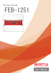
Dimensions ( W x D x H )
195 mm x 268 mm x 80 mm (7.7” x 10.5” x 3.1”)
Construction
Fanless aluminum chassis design
Environment
Operating temperature - ambient with airflow:
20°C to 70°C with industrial grade devices
(According to IEC60068-2-1, IEC60068-2-2, IEC60068-2-14)
Storage temperature: -20°C to 80°C
Relative humidity: 10% to 93% (Non-Condensing)
Certifications
CE approval
FCC Class A
* All specifications and photos are subject to change without notice*
8 PER33A Embedded System User’s Manual 1.2 Mechanical Dimensions
9 PER33A Embedded System User’s Manual Chapter 2: Jumpers and Connectors Locations
This chapter describes the jumpers and connectors on the systems’
motherboard. Note that the following procedures are generic for PER33A
Embedded System
Before You Begin
• Ensure you have a stable, clean working environment. Dust and dirt can
get into components and cause a malfunction. Use containers to keep small
components separated.
• Adequate lighting and proper tools can prevent you from accidentally
damaging the internal components. Most of the procedures that follow
require only a few simple tools, including the following:
• A Philips screwdriver
• A flat-tipped screwdriver
• A set of jewelers screwdrivers
• A grounding strap and anti-static pad
• Using your fingers can disconnect most of the connections. It is recommended that you do not use needle-nosed pliers to disconnect connections
as these can damage the soft metal or plastic parts of the connectors.
• Before working on internal components, make sure that the power is off.
Ground yourself before touching any internal components, by touching a
metal object. Static electricity can damage many of the electronic
components. Humid environment tend to have less static electricity than dry
environments. A grounding strap is warranted whenever danger of static
electricity exists.
Precautions
Computer components and electronic circuit boards can be damaged by
discharges of static electricity. Working on the computers that are still connected to a power supply can be extremely dangerous.
Follow the guidelines below to avoid damage to your computer or yourself:
• Always disconnect the unit from the power outlet whenever you are
working inside the case.
• If possible, wear a grounded wrist strap when you are working inside the
computer case. Alternatively, discharge any static electricity by touching the
bare metal chassis of the unit case, or the bare metal body of any other
grounded appliance.
• Hold electronic circuit boards by the edges only. Do not touch the components on the board unless it is necessary to do so. Don’t flex or stress the
circuit board.
• Leave all components inside the static-proof packaging that they shipped
with until they are ready for installation.
• Use correct screws and do not over tighten screws.
10 PER33A Embedded System User’s Manual 2.1 Jumper Settings
2.1.1 CMOS Clear pin header
Connector location: JP4
Pi
n
1
2
3
Signal
RTCRST#
PU
RTCRST#
CLR_CLE
AR
Jump Function
Definition
*1-2
Normal
2-2
CMOS_CLEAR
*=Default setting
11 PER33A Embedded System User’s Manual Chapter 3: Onboard Connector
3.1 External Connectors
3.1.1 USB Ports
Connector type: Dual USB port
Connector location: CN10
Pin
1
2
3
4
5
6
Definition
+5V
USB 0 USB 0 +
GND
+5V
USB 1 -
Pin
7
8
9
10
11
12
Definition
USB 1 GND
GND
GND
GND
GND
3.1.2 eSATA Ports
Pin
1
2
3
4
Definition
GND
SATA TXP4
SATA TXN4
GND
Pin
5
6
7
Definition
SATA RXN4
SATA RXP4
GND
3.1.3 Lockable USB Port
3.1.4 ATX Power On/Off Switch
Connector location: SW1
Pin
On
Off
Definition
Blue light
Red light
12 PER33A Embedded System User’s Manual 3.1.5 DC input connector (9~30V)
Connector type: Power F 90
Connector location: CN1
Pin
1
2
3
Definition
VIN
VIN
GND
Pin
4
5
Definition
GND
GND
3.1.6: ATX Remote ON/OFF Switch
Connector type: 2-pin switch
Connector location: J3
Pin
1
2
Signal
GND
PBT PU
3.1.7 GPIO Connector (4 x digital input and 4 x digital output)
Connector type: DB-15 port, 10-pin header (2x5), 2.0 mm-M-180
Connector location: JP2
Pin # Pin #
for
for
DB15 pin
header
1
2
4
7
7
4
10
10
13
Signal Pin # Pin #
for
for
DB15 pin
header
GND 2
3
GPO3 5
9
GPI1 8
6
GPI4 11
N/A
14
Signal Pin # Pin #
for
for
DB15 pin
header
GPO1 3
5
GPO4 6
1
GPI2 9
8
N/A
12
N/A
15
Signal
GPO2
VCC5
GPI3
N/A
N/A
13 PER33A Embedded System User’s Manual 3.1.8 VGA Port
Connector type: DB-15 port, 15-pin D-Sub
Connector location: CN9B
Pin
1
2
3
4
5
6
7
8
Definition
RED_VGA
GREEN_VGA
BLUE_VGA
GND
GND
GND
GND
GND
Pin
9
10
11
12
13
14
15
Definition
VGA_VCC(5V)
GND
GND
DDCDATA_VGA
HSYNC_VGA
VSYNC_VGA
DDCCLK_VGA
3.1.9 Speaker-out Jack
Connector type: 5-pin jack
Connector location: CN11B
Pin
1
2
3
4
5
Definition
GND
Speak Out - R
NC
NC
Speak Out - L
3.1.10 Mic-in Jack
Connector type: 5-pin jack
Connector location: CN11A
Pin
1
2
3
4
5
Definition
AU GND
MIC Out - L
AU GND
MIC JD1
MIC Out - R
14 PER33A Embedded System User’s Manual 3.1.11 LAN1 and LAN2 Ports
Connector type: RJ45 port with LEDs
Connector location: CN3B & CN6B
Act
Orange Blinking
Orange Off
Green Always lighted
Green Off
Pin
09
11
13
15
17
19
21
25
Status
Data Activity
No Activity
Linked
No Link
Definition
LAN1 M0P
LAN1 M1P
LAN1 M2N
LAN1 M3P
LAN1 LED1P
LAN1 LED2P
GND
GND
Pin
10
12
14
16
18
20
24
28
Definition
LAN1 M0N
LAN1 M2P
LAN1 M1N
LAN1 M3N
LAN1 LED ACT#
LAN1 LINK#
GND
GND
3.1.12 Serial Interface ( COM1 ~ COM4 )
Connector size: 44 Pin D-Sub
Connector location: CN4
Pin
1
3
5
7
9
11
13
15
17
19
21
23
25
27
29
31
33
Definition
GN10 1
GN10 3
GND
GN10 7
GN10 9
GN10 11
GN10 13
GND
GN10 17
GN10 19
GN10 21
GN10 23
GND
GN10 27
GN10 29
GN10 31
GN10 33
Pin
2
4
6
8
10
12
14
16
18
20
22
24
26
28
30
32
34
Definition
GN10 2
GN10 4
GN10 6
GN10 8
GND
GN10 12
GN10 14
GN10 16
GN10 18
GND
GN10 22
GN10 24
GN10 26
GN10 28
GND
GN10 32
GN10 34
15 PER33A Embedded System User’s Manual 35
37
39
41
43
GND
GN10 37
SP4 RI TI
NC
NC
36
38
40
42
44
GN10 36
GN10 38
GND
NC
NC
The 44-pin D-Sub connector connects to the following COM
ports (A to D) through a DB44-pin cable.
COM 1 ( RS232 ) labeled “ A “on DB9 Cable Connector
DB44 pin
Definitio
DB9 pin
DB9 pin #
DB44 pin #
#
n
#
1
1
DCD1
2
2
3
3
TXD1
4
4
5
5
GND
6
6
7
7
RTS1
8
8
9
9
RI1
10
Definitio
n
RXD1
DTR1
DSR1
CTS1
GND
COM 2 ( RS232 ) labeled “ B “on DB9 Cable Connector
DB44 pin
Definitio
DB9 pin
DB9 pin #
DB44 pin #
#
n
#
11
1
DCD2
12
2
13
3
TXD2
14
4
15
5
GND
16
6
17
7
RTS2
18
8
19
9
RI2
20
Definitio
n
RXD2
DTR2
DSR2
CTS2
GND
COM 3 ( RS232 ) labeled “ C “on DB9 Cable Connector
DB44 pin
Definitio
DB9 pin
DB9 pin #
DB44 pin #
#
n
#
21
1
DCD3
22
2
23
3
TXD3
24
4
25
5
GND
26
6
27
7
RTS3
28
8
29
9
RI3
30
Definitio
n
RXD3
DTR3
DSR3
CTS3
GND
COM 4 ( RS232 ) labeled “ D “on DB9 Cable Connector
DB44 pin
Definitio
DB9 pin
DB9 pin #
DB44 pin #
#
n
#
31
1
DCD4
32
2
33
3
TXD4
34
4
Definitio
n
RXD4
DTR4
16 PER33A Embedded System User’s Manual 35
37
39
5
7
9
GND
RTS4
RI4
36
38
40
6
8
DSR4
CTS4
GND
Note: Pin 39 is defined as external power with selection for 5V or 12V
through JP9.
COM 2 ( RS422 ) labeled “ B “on DB9 Cable Connector
DB44 pin
Definitio
DB9 pin
DB9 pin #
DB44 pin #
#
n
#
11
1
TXD12
2
13
3
RXD+
14
4
15
5
GND
16
6
17
7
RTS+
18
8
19
9
CTS20
Definitio
n
TXD+
RXDRTSCTS+
GND
COM 2 ( RS485 ) labeled “ B “on DB9 Cable Connector
DB44 pin
Definitio
DB9 pin
DB9 pin #
DB44 pin #
#
n
#
TXD11
1
12
2
RXDReserve
13
3
14
4
d
Reserve
15
5
16
6
d
Reserve
17
7
18
8
d
Reserve
19
9
20
d
Definitio
n
TXD+
RXD+
Reserve
d
Reserve
d
Reserve
d
Reserve
d
3.1.13 DVI Port
Connector size: DB-9 port
Connector location: COM4
Pin
1
3
5
7
9
Definition
HDMI DATA2
N
DVI GND
NC
HDMI CTL
SDA
HDMI DATA1
N
Pin
2
Definition
HDMI DATA2 P
4
6
8
NC
HDMI CTL CLK
DC VSYNC
VGA
HDMI DATA1 P
10
17 PER33A Embedded System User’s Manual 11
13
15
17
19
21
23
C1
C3
C5A
DVI GND
NC
DVI GND
HDMI DATA0
N
DVI GND
DC CLK VGA
HDMI LKP
DC RED
VGA
DC BLUE
VGA
DVI GND
12
14
16
18
NC
HDMIC PWR S
HDMIC HPDET
HDMI DATA0 P
20
22
24
C2
DC DATA VGA
NC
HDMI LKN
DC GREEN
VGA
DC HSYNC
VGA
DVI GND
C4
C5B
3.2 Internal Connectors
3.2.1 USB Connector
Connector size: 6-pin JST wafer (1x6), 2 mm pitch
Connector location: J12
Pin
1
2
3
4
5
6
Definition
+5V
USB 10USB 10+
USB 11USB 11+
GND
3.2.2 COM5 Connector
Connector type: 10-pin boxed header (2x5), 2.0 mm
Connector location: CN5
Pin
1
3
5
7
9
Definition
SP5_DCD
SP5_TXD
GND
SP5_RTS
SP5_RI
Pin
2
4
6
8
10
Definition
SP5_RXD
SP5_DTR
SP5_DSR
SP5_CTS
GND
3.2.3 Parallel Connector
Connector type: 26-pin boxed header (2x13), 2.0 mm
Connector location: CN4
18 PER33A Embedded System User’s Manual Pin
1
2
3
4
5
6
7
8
9
10
11
12
13
Definition
LPT RP
STB#
LPT RP
PRD0
LPT RP
PRD1
LPT RP
PRD2
LPT RP
PRD3
LPT RP
PRD4
LPT RP
PRD5
LPT RP
PRD6
LPT RP
PRD7
LPT
ACK#R
LPT BUSY
LPT PE
LPT SLCT
Pin
14
Definition
LPT AFD#R
15
LPT ERR#
16
LPT INIT#R
17
LPT SLIN#R
18
GND LPT
19
GND LPT
20
GND LPT
21
GND LPT
22
GND LPT
23
GND LPT
24
25
26
GND LPT
GND LPT
NC
3.2.4 Reset Connector
Connector type: 2 pin header (1x2), JST 2.5 mm
Connector location: J2
Pin Signal
1
RESET#
2
GND
3.2.5 CPU Fan Connector
Connector type: 4-pin Wafer (1x4), 2.54 mm M-180
Connector location: J1 & J14
Pin
1
2
3
4
Signal
GND
VCC_12
CPU_FANIN P
CPU_FANOUT R
19 PER33A Embedded System User’s Manual 3.2.6 Internal Power/HDD/LAN Power/LAN Active LED
Connector type: 14-pin header (2x7), 2.54 mm M-180
Connector location: J4
Pin
1
3
5
Definition
POWER_OK
HDD_LED#
LAN1_LINK#
Pin
2
4
6
7
LAN1_ACT#
8
9
LAN2_LINK#
10
11
LAN2_ACT#
12
13
H/W RESET
14
Definition
VCC_LEDPOWER
HDD_LEDPOWER
LAN1LINK_LEDPOWE
R
LAN1ACT_LEDPOWE
R
LAN2LINK_LEDPOWE
R
LAN2ACT_LEDPOWE
R
GND
3.2.7: Line-in connector
Connector type: 4 pin header (1x4),2.5 mm M-180
Connector location: J15
Pin Definition
1
Line1 LP
2
GND
3
Line1 JD
4
Line1 RP
3.2.8 SMBus Pin Header
Connector type: 3-pin header (1x3), 2.54 mm M-180
Connector location: J8
Pin
1
2
3
Signal
SMbus_CLK
SMbus_data
GND
3.2.9 Power Output Connector
Connector type: 4-pin (2x2) AUX 3.5mm
Connector location: CON1
20 PER33A Embedded System User’s Manual Pin
1
2
3
4
Signal
GND
GND
VIN Power
VIN Power
3.2.10 LVDS Connector
Channel A :
Connector type: 20-pin DF13-20DP 1.25mm
Connector location: CN7
Pin
1
3
Pin
2
4
Definition
LVDS_DDCDATA
LVDS_A0P
5
7
Definition
LVDS_DDCCLK
VCC_LCD(5V
Or3.3V)
NC
NC
6
8
9
11
13
15
17
19
GND
LVDS_ACLKP
LVDS_ACLKN
GND
LVDS_A2P
LVDS_A2N
10
12
14
16
18
20
LVDS_A0N
VCC_LCD(5V
Or3.3V)
LVDS_A1P
LVDS_A1N
GND
V_INV (12V)
V_INV (12V)
GND
Channel B :
Connector type: 20-pin DF13-20DP 1.25mm
Connector location: CN8
Pin
1
3
Pin
2
4
Definition
LVDS_DDCDATA
LVDS_A0P
5
7
Definition
LVDS_DDCCLK
VCC_LCD(5V
Or3.3V)
NC
NC
6
8
9
11
13
15
17
19
GND
LVDS_ACLKP
LVDS_ACLKN
GND
LVDS_A2P
LVDS_A2N
10
12
14
16
18
20
LVDS_A0N
VCC_LCD(5V
Or3.3V)
LVDS_A1P
LVDS_A1N
GND
V_INV (12V)
V_INV (12V)
GND
21 PER33A Embedded System User’s Manual 3.2.11 LVDS Backlight Connector
Connector type: 7-pin header JST (1x7) - 2.5 mm M-180
Connector location: J1
Pin
1
2
3
4
5
6
7
Definition
Vcc5
V_INV (12V)
V_INV (12V)
CCFLBKLTCTRL
GND
GND
M_BKLTEN
3.2.12 SATA connector
Connector type: Standard SATA II 7P
Connector location: CN12 & CN13
Pin
1
2
3
4
5
6
7
Defintion
GND
SATA TXP1
SATA TXN1
GND
SATA RXN1
SATA RXP1
GND
3.2.13 SATA Power connector
Connector type: 4-pin Wafer, 2.54mm
Connector location: CN14 & CN15
Pin
1
2
3
4
Definition
+12V
GND
GND
VCC5
22 PER33A Embedded System User’s Manual 3.2.14 SATA DOM Power connector
Connector type: 4-pin JST wafer (2x2), 2.54 mm
Connector location: J16 & J17
Pin
1
2
Definition
+12V
GND
3.24 COM4 RI Pin header
Connector type: 5-pin header, 2.0mm
Connector location: J9
Pin
1
2
3
4
5
Definition
VCC5
SP4 RI T
+12V
SP4 RI T
SP4 R
3.24 GPIO LED connector
Connector type: 4-pin , 2.0 mm
Connector location: JP1
Pin
1
2
3
4
Definition
GPO LED0
GND
GPO LED1
GND
23 PER33A Embedded System User’s Manual Chapter4: Getting Started
This chapter provides more information including information for the
installation of components into the PER33A Embedded system. The
installation of memory modules and an operating system are explained.
4.1 Installing System Memory
The PER33A supports DDR3 800 SODIMM (Maximum 2GB)
.
Disconnect all power supplies to the board before installing a memory
module to prevent damage to the board and memory module.
To install a memory module:
Step 1: Locate the memory module slots and then push the ejector tab on
the motherboard.
Step 2: Align the notch on the memory module and the socket slot, and
insert the memory module until the connectors fully inserted.
24 PER33A Embedded System User’s Manual Step 3: Press the module down and then lower it down in place. Press the
module by using the edges of the module.
The retaining clips lock onto the module and the memory modules are
secured in place.
4.2 Install the Processor
Step 1: Locate the processor (CPU) socket on the motherboard.
25 PER33A Embedded System User’s Manual Step 2: Turn Socket Lock to the unlocked position.
Step 3: Align the Gold Triangular Mark over Pin 1, and install the CPU.
Step 4: Turn the Socket Lock to the locked position to secure in place.
Step 5: Apply thermal grease to the top of CPU.
Step 6: Align the heat sink over the processor mounting studs, then lower
the heat sink in place. Secure the heat sink with the provided screws.
26 PER33A Embedded System User’s Manual 4.3 Installing a SATA Hard Drive
Step 1: Remove the mounting screw of the bottom cover.
Step 2: Remove the screws that secure the drive bay to the chassis.
Step 3: Secure the HDD as shown in the following image.
Step 4: Align the HDD assembly over the chassis and connect the SATA
power and SATA data cables as shown in the following image.
Step 4: Secure the HDD drive bay on the chassis with provided screws.
27 PER33A Embedded System User’s Manual Chapter 5: BIOS Setup
This chapter describes how to use the BIOS setup program for the PER33A
Embedded system. The BIOS screens provided in this chapter are for reference only and may change if the BIOS is updated in the future.
About BIOS Setup
The BIOS (Basic Input and Output System) Setup program is a menu driven
utility that enables you to make changes to the system configuration and
tailor your system to suit your individual work needs. It is a ROM-based
configuration utility that displays the system’s configuration status and
provides you with a tool to set system parameters.
These parameters are stored in non-volatile battery-backed-up CMOS RAM
that saves this information even when the power is turned off. When the
system is turned back on, the system is configured with the values found in
CMOS.
With easy-to-use pull down menus, you can configure such items as:
Hard drives, diskette drives, and peripherals
Video display type and display options
Password protection from unauthorized use
Power management features
The settings made in the setup program affect how the computer performs. It
is important, therefore, first to try to understand all the Setup options, and
second, to make settings appropriate for the way you use the computer.
When to Configure the BIOS
This program should be executed under the following conditions:
▪▪When changing the system configuration
▪▪When a configuration error is detected by the system and you are
prompted to make changes to the Setup program
▪▪When resetting the system clock
▪▪When redefining the communication ports to prevent any conflicts
▪▪When making changes to the Power Management configuration
▪▪When changing the password or making other changes to the security
setup
Normally, CMOS setup is needed when the system hardware is not consistent with the information contained in the CMOS RAM, whenever the
CMOS RAM has lost power, or the system features need to be changed.
Default Configuration
Most of the configuration settings are either predefined according to the
Load Optimal Defaults settings which are stored in the BIOS or are auto-
28 PER33A Embedded System User’s Manual matically detected and configured without requiring any actions. There are a
few settings that you may need to change depending on your system
configuration.
Entering Setup
When the system is powered on, the BIOS will enter the Power-On Self Test
(POST) routines. These routines perform various diagnostic checks; if an
error is encountered, the error will be reported in one of two different ways:
If the error occurs before the display device is initialized, a series of
beeps will be transmitted.
If the error occurs after the display device is initialized, the screen will
display the error message.
Powering on the computer and immediately pressing <Del> allows you to
enter Setup. Another way to enter setup is to power on the computer and
wait for the following message during the POST screen:
To enter setup, press <CTRL-ALT-ESC> and the <Del> key at the same
time before booting (POST):
Legends
Key
Right and Left arrows
Up and Down arrows
<Esc>
+ (plus key)
- (minus key)
Tab
<F1>
<F10>
<Enter>
Function
Moves the highlight left or right to select a menu.
Moves the highlight up or down between submenus or fields.
Exits to the BIOS Setup Utility.
Scrolls forward through the values or options of
the highlighted field.
Scrolls backward through the values or options of
the highlighted field.
Selects a field.
Displays General Help.
Saves and exits the Setup program.
Press <Enter> to enter the highlighted submenu.
Scroll Bar
When a scroll bar appears to the right of the setup screen, it indicates that
there are more available fields not shown on the screen. Use the up and
down arrow keys to scroll through all the available fields.
29 PER33A Embedded System User’s Manual Submenu
When “u“ appears on the left of a particular field, it indicates that a submenu
which contains additional options are available for that field. To display the
submenu, move the highlight to that field and press <Enter>.
BIOS Setup Utility
Once you enter the AMI BIOS Setup Utility, the Main Menu will appear on
the screen. The main menu allows you to select from six setup functions and
one exit choices. Use arrow keys to select among the items and press
<Enter> to accept or enter the submenu.
5.1 Main menu
The Main menu is the first screen that you will see when you enter the BIOS
Setup Utility.
BIOS Information:
Displays the detected BIOS information.
Memory information:
Displays the detected system memory information.
System Time:
The time format is <hour>, <minute>, <second>. The time is based on the
24-hour military-time clock. For example, 1 p.m. is 13:00:00. Hour displays
30 PER33A Embedded System User’s Manual hours from 00 to 23. Minute displays minutes from 00 to 59. Second displays
seconds from 00 to 59.
System Date
The date format is <day>, <month>, <date>, <year>. Day displays a day,
from Sunday to Saturday. Month displays the month, from January to December. Date displays the date, from 1 to 31. Year displays the year, from
1999 to 2099.
5.2 Advanced
The Advanced menu allows you to configure your system for basic operation.
Some entries are defaults required by the system board, while others, if
enabled, will improve the performance of your system or let you set some
features according to your preference.
Setting incorrect field values may cause the system to malfunction.
Launch PXE OpROM
Enables or Disables the boot option for legacy network devices.
S5 RTC Wake Settings
Configure the S5 RTC wake up setting.
CPU Configuration
This section is used to configure the CPU. It also detects CPU information.
SATA Configuration
This section is used to configure the SATA drives.
31 PER33A Embedded System User’s Manual Intel IGD SWSCI OpRegion
Configures the Intel graphics display.
Intel TXT(LT) Configuration
Configures the Intel Trusted Execution technology function.
USB Configuration
Configures the USB devices.
Super IO Configuration
This section is used to configure the I/O functions supported by the onboard
Super I/O chip.
H/W Monitor
This section is used to configure the hardware monitoring events such as
temperature, fan speed and voltages.
Thermal Configuration
Configures the intelligent power sharing function.
AMT Configuration
Configures the AMT function.
S5 RTC Wake settings
This section is used to configure the wake up function.
Wake System with Fixed Time
Enables and disables the system’s wake on alarm event. When enabled, the
system will wake up on the specified time.
32 PER33A Embedded System User’s Manual CPU Configuration
This section is used to configure the CPU. It displays detected CPU
information.
Hyper-Threading
Enable this field for Windows XP and Linux which are optimized for Hyper
Threading technology. Select disabled for other operating systems not
optimized for Hyper-Threading technology. When disabled, only one thread
per enabled core is enabled.
Active Processor Cores
Used to enter the number of cores to enable in each processor package.
Limit CPUID Maximum
The CPUID instruction of some newer CPUs returns a value greater than 3.
The default is Disabled because this problem does not exist in the Windows
series operating systems. If you are using an operating system other than
Windows, this problem may occur. To avoid this problem, enable this field to
limit the return value to 3 or less than 3.
Hardware Prefetcher
Turns on or off the MLC streamer prefetcher.
Adjacent Cache Line Prefetch
Enables or disables the adjacent cache line prefetch.
33 PER33A Embedded System User’s Manual Intel Virtualization Technology
When this field is set to Enabled, the VMM can utilize the additional
hardware capabilities provided by Vanderpool Technology.
Power Technology
Configures the power management features.
TDC Limit
Used to select the TDC limit.
TDP Limit
Used to select the TDP limit.
SATA Configuration
This section is used to configure the SATA devices,
SATA Mode
IDE Mode
This option configures the Serial ATA drives as Parallel
ATA storage devices.
AHCI Mode This option allows the Serial ATA devices to use AHCI
( Advanced Host Controller Interface )
RAID Mode This option allows you to create RAID or Intel Matrix
Storage configuration on Serial ATA devices.
Intel IGD SWSCI OpRegion
This section is used to configure the Intel graphics display.
34 PER33A Embedded System User’s Manual DVMT/ FIXED Memory
Selects the DVMT/FIXED mode memory size used by the internal graphics
devices.
IGD – Boot Type
Selects the Video device that will be activated during POST. This will not
affect any external graphics that may be present.
LCD Panel Type
Selects the LCD panel used by the internal graphics device.
Intel TXT( LT) Configuration
This section is used to configure the Intel Trusted Execution technology.
35 PER33A Embedded System User’s Manual Intel TXT( LT) Support
The options are Enabled and Disabled.
USB Configuration
This section is used to configure USB devices.
Legacy USB Support
Enable
Enabled legacy USB
Auto
Disables support for legacy when no USB devices are
connected.
Disable
Keeps USB devices available only for EFI applications.
36 PER33A Embedded System User’s Manual EHCI Hand-off
This is a workaround for operating systems that do not support EHCI handoff. The EHCI ownership is claimed by the EHCI driver.
Device Reset Timeout
Selects the USB mass storage device start unit command timeout.
Super IO Configuration
This section is used to configure the I/O functions supported by the onboard
Super I/O chip.
Serial Port 0 to 4 Configuration
Selects the IO/IRQ setting of the I/O devices.
Parallel Port Configuration
Configures the parallel port.
37 PER33A Embedded System User’s Manual IDE Configuration
This section is used to configure the IDE drives.
ATA/IDE Configuration
This field is used to configure the IDE drives. The options are Disabled,
Compatible and Enhanced.
Configure SATA as:
IDE
This option configures the Serial ATA drives as Parallel
ATA physical storage device.
AHCI
This option configures the Serial ATA drives to use
AHCI (Advanced Host Controller Interface). AHCI allows
the storage driver to enable the advanced Serial ATA
features which will increase storage performance.
Primary IDE Master to Third IDE Master
When you enter the BIOS Setup Utility, the BIOS will auto detect the existing
IDE devices then displays the status of the detected devices. To configure
an IDE drive, move the cursor to a field then press <Enter>.
IDE Detect Time Out (Sec)
Selects the time out value for detecting ATA/ATAPI devices.
38 PER33A Embedded System User’s Manual USB Configuration
This section is used to configure USB devices.
Legacy USB Support
Due to the limited space of the BIOS ROM, the support for legacy USB
keyboard (in DOS mode) is by default set to Disabled. With more BIOS
ROM space available, it will be able to support more advanced features as
well as provide compatibility to a wide variety of peripheral devices.
If a PS/2 keyboard is not available and you need to use a USB keyboard to
install Windows (installation is performed in DOS mode) or run any program
under DOS, set this field to Enabled.
USB 2.0 Controller Mode
Sets the USB 2.0 controller mode to HiSpeed (480 Mbps) or FullSpeed (12
Mbps).
BIOS EHCI Hand-Off
Enable this field when using operating systems without the EHCI hand-off
support.
Hotplug USB FDD Support
Enables support for USB FDD hot plug.
39 PER33A Embedded System User’s Manual Super IO Configuration
This section is used to configure the I/O functions supported by the onboard
Super I/O chip.
Serial Port1 to Port6 Address
Auto The system will automatically select an I/O address for the onboard
serial port. 3F8, 2F8, 3E8, 2E8, 2F0, 2E0 Allows you to manually select an
I/O address for the onboard serial port. Disabled Disables the onboard serial
port.
Serial Port1 IRQ to Serial Port6 IRQ
These fields are used to select an IRQ for the onboard serial port 1, 2, 3, 4,
5 or 6.
40 PER33A Embedded System User’s Manual Serial Port1 Frequency Mode
This field is used to select the frequency mode of serial port 1. The options
are RS232, RS422 and RS485.
Serial Port2 Frequency Mode
This field is used to select the frequency mode of serial port 2. The options
are RS232, RS422 and RS485.
41 PER33A Embedded System User’s Manual If you selected RS422 or RS485 in the “Serial Port1 Frequency Mode”
and/or “Serial Port2 Frequency Mode” field, the “Serial Port1 Frequency
Select” and/or “Serial Port2 Frequency Select” field will appear prompting
you to select the frequency setting. The options are 115200 bps and
921600 bps.
Hardware Health Configuration
This section is used to configure the hardware monitoring events such as
temperature, fan speed and voltages
H/W Health Function
Enables or disables the hardware monitoring function.
CPU Temperature and System Temperature
42 PER33A Embedded System User’s Manual Detects and displays the current temperature of the CPU and the internal
temperature of the system.
Fan Speed
Not applicable
CPU Core to +5.00V
Detects and displays the output voltages.
5.3 Boot
Boot Settings Configuration
This section is used to configure settings during system boot.
Boot Device Priority
This section is used to select the boot priority sequence of the devices.
Removable Drives
This section is used to select the boot priority sequence of the removable
drives.
43 PER33A Embedded System User’s Manual Boot Settings Configuration
This section is used to configure settings during system boot.
Quick Boot
When Enabled, the BIOS will shorten or skip some check items during
POST. This will decrease the time needed to boot the system.
Quiet Boot
Enabled Displays OEM logo instead of the POST messages.
Disabled Displays normal POST messages.
Bootup Num-Lock
This allows you to determine the default state of the numeric keypad. By
default, the system boots up with NumLock on wherein the function of the
numeric keypad is the number keys. When set to Off, the function of the
numeric keypad is the arrow keys.
PS/2 Mouse Support
The options are Auto, Enabled and Disabled.
System Keyboard
Detects the system keyboard.
Hit ‘DEL’ Message Display
When enabled, the system displays the “Press DEL to run Setup” message
during POST.
Interrupt 19 Capture
When enabled, it allows the optional ROM to trap interrupt 19.
44 PER33A Embedded System User’s Manual Boot Device Priority
This section is used to select the boot priority sequence of the devices.
1st to 3rd Boot Device
Selects the drive to boot first, second and third, respectively. The BIOS will
boot the operating system according to the sequence of the drive selected.
5.4 Chipset
This section is used to configure the system based on the specific features
of the chipset.
Setting incorrect field values may cause the system to malfunction.
45 PER33A Embedded System User’s Manual North Bridge Configuration
This section is used to configure the north bridge features.
Initiate Graphic Adapter
Selects the graphics controller to use as the primary boot device.
Internal Graphics Mode Select
Selects the amount of system memory used by the internal graphics device.
DVMT Mode Select
The options are Fixed mode and DVMT mode.
DVMT/Fixed Memory This field is used to select the graphics memory size
used by DVMT/Fixed mode.
Boot Display Device
This field is used to select the type of display to use when the system boots.
46 PER33A Embedded System User’s Manual Flat Panel Type
Selects the type of flat panel connected to the system. The supported LVDS
are 640x480 18bit, 800x600 18bit, 1024x768 18bit and 1280x800 18bit.
South Bridge Configuration
This section is used to configure the south bridge features.
USB Functions
Enables or disables USB devices.
USB 2.0 Controller
This field is used to enable or disable the Enhanced Host Controller Interface (USB 2.0).
HDA Controller
Enables or disables the onboard audio.
47 PER33A Embedded System User’s Manual SMBUS Controller
Enables or disables the SMBUS.
Restore On AC Power Loss
Power Off When power returns after an AC power failure, the system’s
power is off. You must press the Power button to power-on the
system.
Power On When power returns after an AC power failure, the system will
automatically power-on.
Last State When power returns after an AC power failure, the system will
return to the state where you left off before power failure occurs.
If the system’s power is off when AC power failure occurs, it will
remain off when power returns. If the system’s power is on when
AC power failure occurs, the system will power-on when power
returns.
Power Type
Selects the type of power used.
PCIE Port 0 and PCIE port 1
Configures the PCIE ports.
48 PER33A Embedded System User’s Manual 5.5 PCIPnP
This section is used to configure settings for PCI/PnP devices.
Setting incorrect field values may cause the system to malfunction.
Plug & Play O/S
Yes: Configures Plug and Play (PnP) devices that are not required to boot in
a Plug and Play supported operating system.
No: The BIOS configures all the devices in the system.
PCI Latency Timer
This feature is used to select the length of time each PCI device will control
the bus before another takes over. The larger the value, the longer the PCI
device can retain control of the bus. Since each access to the bus comes
with an initial delay before any transaction can be made, low values for the
PCI Latency Timer will reduce the effectiveness of the PCI bandwidth while
higher values will improve it.
IRQ3 to IRQ15
Available: The specified IRQ is available for PCI/PnP devices.
Reserved: The specified IRQ is reserved for Legacy ISA devices.
49 PER33A Embedded System User’s Manual 5.6 Security
Change Supervisor Password
This field is used to set or change the supervisor password.
To set a new password:
Step 1: Select the Change Supervisor Password field then press <Enter>.
Step 2: Type your password in the dialog box then press <Enter>.
You are limited to eight letters/numbers.
Step 3: Press <Enter> to confirm the new password.
Step 4: When the Password Installed dialog box appears, select OK.
To change the password, repeat the same steps above.
To clear the password, select Change Supervisor Password then press <Enter>. The Password Uninstalled dialog box will appear.
If you forgot the password, you can clear the password by erasing the
CMOS RTC (Real Time Clock) RAM using the RTC Clear jumper. Refer to
chapter 2 for more information.
Change User Password
This field is used to set or change the user password.
To set a new password:
Step 1: Select the Change User Password field then press <Enter>.
Step 2: Type your password in the dialog box then press <Enter>.
You are limited to eight letters/numbers.
Step 3: Press <Enter> to confirm the new password.
Step 4: When the Password Installed dialog box appears, select OK.
To change the password, repeat the same steps above.
50 PER33A Embedded System User’s Manual 5.7 Exit
Save Changes and Exit
To save the changes and exit the Setup utility, select this field then press
<Enter>. A dialog box will appear. Confirm by selecting Yes. You can also
press <F10> to save and exit Setup.
Discard Changes and Exit
To exit the Setup utility without saving the changes, select this field then
press <Enter>. You may be prompted to confirm again before exiting. You
can also press <ESC> to exit without saving the changes.
Discard Changes
To discard the changes, select this field then press <Enter>. A dialog box
will appear. Confirm by selecting Yes to discard all changes made and
restore the previously saved settings.
Load Optimal Defaults
Loads the optimal default values from the BIOS ROM.
Load Failsafe Defaults
Loads the fail-safe default values from the BIOS ROM.
51 PER33A Embedded System User’s Manual Appendix A: Power Consumption
Test Configuration
System Configuration
Chassis
CPU
Memory
HDD
FDD
CD-ROM
CompactFlash device
Power Supply
Add-on Card
CPU Cooler
System Fan
Keyboard
Mouse
Sys#1
PER 33A Embedded system
®
Intel Atom™ processor D525 (1M Cache, 1.80
GHz)
Apacer 1GB SOD PC3-10600 (industrial)
N/A
N/A
N/A
Apacer 8G (industrial)
POWER ADAPTER SPI:G.P FSP65-AAB(N091)
N/A
PER33A HEATSINK
N/A
LEMEL B-5201-P
GENIVS EASY MOUSE PS/2
Power Consumption Measurement
Purpose
The purpose of the power consumption test is to verify the power dissipation
of the system and the load of the power supply.
Test Equipment
PROVA CM-07 AC/DC CLAMP METER
Device Under Test
DUT: Sys #1
Test Procedure
1. Power up the DUT and then boot Windows XP.
2. Enter the standby mode (HDD power down).
3. Measure the power consumption and record it.
4. Run the Burn-in test program to apply 100% full loading.
5. Run the Intel Kpower program.
6. Run the LAN Packet Counter and Receive program.
52 PER33A Embedded System User’s Manual Test Data
Sys #1
+12V
Full-Loading Mode
Total
Standby Mode
Total
2.18A
26.16W
0.9A
10.8W
53 PER33A Embedded System User’s Manual Appendix B: GPI/O Programming guide
GPI/O (General Purpose Input/Output) pins are provided for custom system
design. This appendix provides definitions and its default setting for the ten
GPI/O pins in the PER33A. The pin definition is shown in the following table:
Pin
GPI/O
Power
Addres Pin
GPI/O
Power
Addres
Mode
On
s
Mode
On
s
Default
Default
1
VCC
2
GND
3
GPO
Low
284h
4
GPI
High
284h
(Bit4)
(Bit0)
5
GPO
Low
284h
6
GPI
High
284h
(Bit5)
(Bit1)
7
GPO
Low
284h
8
GPI
High
284h
(Bit6)
(Bit2)
9
GPO
Low
284h
10
GPI
High
284h
(Bit7)
(Bit3)
J8 - GPI/O connector
Control the GPO pin (3/5/7/9) level from I/O port 284h bit (4/5/6/7).
The bit Set/Clear indicated output High/Low.
GPIO Programming Sample Code
#define GPIO_PORT 0x284
#define GPO3 (0x01 << 4)
#define GPO5 (0x01 << 5)
#define GPO7 (0x01 << 6)
#define GPO9 (0x01 << 7)
#define GPO3_HI outportb(GPIO_PORT, 0x10)
#define GPO3_LO outportb(GPIO_PORT, 0x00)
#define GPO5_HI outportb(GPIO_PORT, 0x20)
#define GPO5_LO outportb(GPIO_PORT, 0x00)
#define GPO7_HI outportb(GPIO_PORT, 0x40)
#define GPO7_LO outportb(GPIO_PORT, 0x00)
#define GPO9_HI outportb(GPIO_PORT, 0x80)
#define GPO9_LO outportb(GPIO_PORT, 0x00)
void main(void)
{
GPO3_HI;
GPO5_LO;
GPO7_HI;
GPO9_LO;
54 PER33A Embedded System User’s Manual Appendix C: Watchdog Timer Setting
Start
Step 1
See “SetupWDT” procedure
#Setup Watchdog Timer Environment
Step 2
See “TimeBaseWDT” procedure
#Initial Watchdog Timer
Users can select second or minute
Step 3
See “TimeCountWDT” procedure
#Set Watchdog Timer Time-out Value
Users can set time-out value
Step 4
See Exit Setup procedure
#Exit Setup Environment
End
ITE8783 WatchDog Programming Guide
#define SUPERIO_PORT 0x2E
#define WDT_SET 0x72
#define WDT_VALUE 0x73
void main(void)
{
#Enter SuperIO Configuration
outportb(SUPERIO_PORT, 0x87);
outportb(SUPERIO_PORT, 0x01);
outportb(SUPERIO_PORT, 0x55);
outportb(SUPERIO_PORT, 0x55);
# Set LDN
outportb(SUPERIO_PORT,0x07);
outportb(SUPERIO_PORT+1 ,0x07);
# Set WDT setting
outportb(WDT_SET,0xC0); # Use the second to come down
# If choose the Minute, change value to 0x40
# Set WDT sec/min
outportb(WDT_VALUE,0x05); #Set 5 seconds
55