1
OBJECT ORIENTED PROGRAMMING
with Java™
Z
x ADVANCED TOPICS x
EUGENE AGEENKO
2003
CONTENTS
CHAPTER A. DESIGN PATTERNS................................................................................................. 3
A.1
A.2
A.3
A.4
A.5
A.6
A.7
A.8
INTRODUCTION .......................................................................................................................... 3
ITERATOR .................................................................................................................................. 3
DECORATOR .............................................................................................................................. 4
COMPOSITE ................................................................................................................................ 4
STRATEGY ................................................................................................................................. 5
ADAPTER ................................................................................................................................... 5
FLYWEIGHT ............................................................................................................................... 6
SINGLETON ................................................................................................................................ 6
CHAPTER B. OBJECT ORIENTED DESIGN................................................................................ 8
B.1
B.2
2
RESPONSIBILITY-DRIVEN DESIGN.............................................................................................. 8
B.1.a Introduction .................................................................................................................. 8
B.1.b OOP Design common steps.......................................................................................... 8
B.1.c Simulation and modeling............................................................................................ 12
CASE STUDY: “THE BALLOON GAME”..................................................................................... 12
B.2.a The task ...................................................................................................................... 12
B.2.b The scenario ............................................................................................................... 13
B.2.c The component identification.....................................................................................14
B.2.d The component design................................................................................................15
B.2.e The implementation.................................................................................................... 18
CHAPTER A. DESIGN PATTERNS
A.1 INTRODUCTION
• Every time new problem is encountered the first thing the programmers usually consider
to do is to overlook the previously solved problems for a similarity and to use them as a
model for the forthcoming solution. This idea is employed in the software design patterns.
• Design pattern describes a proven solution to a problem which can be used as a model
for handle many other problems in a similar way. Patterns became important in the
development of Object-Oriented programs because they aid in designing architecture and
relationship between software components at a higher level of abstraction than classes.
• At the highest level of abstraction the OOP program is seen as a collection of interacting
agents. Certain types of relationships appear over and over in many different
applications. Design patterns extract the fundamental features of these associations.
Design patterns speed the process of finding a right architecture or design solution for the
software without the need to “reinvent the wheel”!
• In the following sections we describe a few most common for OOP design patterns. Many
of these patterns have been already encountered earlier in the course book.
A.2 ITERATOR
• The Iterator (also known as enumerator or enumeration) is used when there is a need to
maintain a collection of some values for an agent (software component). The Iterator
provides a way to access the elements of the collection sequentially without exposing the
underlying representation or implementation details.
• The Iterator is used to reduce the amount of information an agent needs to know in order
to have access to the elements in the collection.
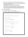
Example
• The Iterator interface (as well as Enumeration interface) for a container class in
Java provides uniform way for accessing elements in many different types of container
when, at the same time, hiding the details of container implementation.
• An object that implements the Iterator interface generates a series of elements, one at
a time. Successive calls to the next method return successive elements of the series.
• For example, to print all elements of a vector v:
Collection v = new Vector();
v.add("A string object");
Dog haku = new Dog("Haku");
v.add(haku);
Iterator i = v.iterator();
while(i.hasNext()) {
Object value = i.next();
System.out.println(value);
}
3
• The code in this example will work well with various types of collections, because the
methods add(Object) and Iterator iterator() are declared in the interface
Collection.
A.3 DECORATOR
• The Decorator (also known as Filter or Wrapper) let you attach additional functionality to
an object dynamically.
• By combining Is-A and Has-A relationship, decorator creates an object that:
wraps around an existing object, and,
when using in place of the wrapped object, adds new behavior without the changing
the interface.
• Even though an inheritance itself can be used for providing new
functionality to an existing abstraction, it is at times not flexible
enough to accommodate situations that must dynamically change
during the course of execution. A decorator wraps around an existing
object and satisfies the same requirements (extended from the same
class or implements the same interface). The decorator delegates all
of its responsibilities to the wrapped object but adds new functionality
to it.
• Decorator can be dynamically introduced or removed to/from the system for (temporarily)
adding/removing additional functionality to/from the existing object.
Example
• The BufferedInputStream is a subclass (Is-A) of InputStream (via
FilterInputStream) that wraps around (Has-A) the InputStream object (which can
be FileInputStream for example) and adds the ability to buffer the input.
• Due to inheritance and substitutability the BufferedInputStream can be used
everywhere where the InputStream is expected.
InputStream in = new FileInputStream("in.txt");
in = new BufferedReader(in);
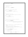
A.4 COMPOSITE
• The Composite design pattern permits the creation of complex objects using only simple
parts.
• The idea is to provide a collection of simple components but also allow these components
to be arbitrarily nested. The composite threats individual objects and their composition
uniformly.
Example
• An example of composite pattern is AWT Java library. It allows creation of complex
layouts of GUI components (the Component class derivates) by using the idea of
Container classes.
• The Container class Is-A Component that can hold several other Components. The
complex layout can be created as follows:
Each container can be used in place of any component.
4
Each container can be associated with the particular layout manager that takes care
about arranging the components in it.
Component layout starts from the parent container class such as Frame or Applet.
By nesting containers (such as Panel for example) one within another various
complex layouts of the visual components can be created.
// ... in the Applet ...
Label l = new Label("The label:")
Panel p = new Panel();
Button yes = new Button("YES");
Button no = new Button("NO");
setLayoutManager(new BorderLayout);
p.setLayoutManager(new FlowLayout);
add(l,BorderLauout.SOUTH);
p.add(yes);
p.add(no);
add(p, BorderLauout.NORTH);
A.5 STRATEGY
• The Strategy allows dynamically change the algorithm that is used to solve a particular
problem.
• It defines a family of algorithms with a similar interface. Each algorithm provides a
different strategy for solving the problem. Yet all have the similar interface allowing to use
the right strategy and even to change from one strategy to another dynamically.
Example
• Example is the strategy of creating layout managers in the AWT Java library. AWT
defines a common interface for the LayoutManager and five standard managers. The
programmer is free to choose from the existing managers or to develop own ones. The
strategy the container uses to arrange components is independent of the particular layout
manager. All the necessary operations for the component arrangement are provided by
the interface.
• An example of custom layout manager is the GraphPaperLayout class – layout
manager developed by Michael Martak. It lays out a container's components in a
rectangular grid, similar to GridLayout. Unlike GridLayout, however, components can
take up multiple rows and/or columns. The layout manager acts as a sheet of graph
paper. When a component is added to the layout manager, the location and relative size
of the component are simply supplied by the constraints as a Rectangle.
A.6 ADAPTER
• The Adapter class acts as an intermediary. It does little work itself but uses the
functionality of the existing class just mapping it into a new interface.
5
• Adapter class is build upon the existing class using composition approach: it has a field
that is a reference to an instance of the existing class. Adapters help to:
hide implementation details,
maintain uniform or customer specific interface whatever implementation is, and
hide unnecessary functionality.
Example
• The class Stack can be built upon the class Vector as well as upon the class
ArrayList. The Stack need only constructor and two methods push and pop. The
functionality of either ArrayList or Vector classes is equally sufficient for that. What
Stack need is to delegate the tasks to the appropriate methods of the class it is
composing upon. Implementation details as well as all the functionality unnecessary for
the Stack remain hidden from the user.
A.7 FLYWEIGHT
• The Flyweight pattern helps to reduce storage costs associated with a large number of
objects that all have similar state. The solution for this problem is to make only one
shared single flyweight object instead of many similar ones.
Example
• All objects in Java are instance of some class. With each class it is necessary to
associate certain information (meta-data), such as the name of the class, description for
the interface, entry points for the constructors and methods, etc.
• All instances of the class basically need to be associated with that information. If this
information were duplicated for each object, it would result in an inappropriate
redundancy. Instead, this information is encapsulated in the class Class, and an
instance of this class exists once for each class in the program, and each object (class
instance) has just a reference to it.
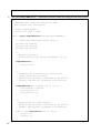
A.8 SINGLETON
• The Singleton is a class that has only one instance.
Example
• The singleton can be created by declaring as follows:
declare the constructor as private, it will prevent the user from creating an instance
of this class
6
declare public static field that is referenced to the object of this class
initialize this field using the private constructor.
public class Singleton {
private static Singleton instance;
public static Singleton getInstance() {
if (instance == null)
instance = new Singleton();
return instance;
}
private Singleton() {
// hide constructor
}
// ... implementation specific
}
7
CHAPTER B. OBJECT ORIENTED DESIGN
Foreword
• The input for the design process is the specification of the required software system. The
end point is a description of the software components: classes, objects and methods and
how they interconnect.
• An important distinction between a specification and a design is as follows. A
specification says what is required and the design says how it will be accomplished. The
specifications are written in the natural language or special formal language (for the
formal specifications), and design is expressed in one of several notations (such as CRC
cards, UML diagrams, algorithms, and system design documentation).
B.1 RESPONSIBILITY-DRIVEN DESIGN
B.1.a Introduction
• Working in an object-oriented language is neither necessary nor sufficient condition for
doing object-oriented programming!
• Most important aspect of OOP is a design technique driven by determination and
delegation of responsibilities, known as responsibility-driven design.
• In OOP system every object is responsible for performing some action, and when we
make an object responsible for performing the actions, we expect a certain behavior.
• Responsibilities also imply a degree of independence and noninterference. Unlike
procedural programming, that is usually doing something to something else, OOP
program works as a collection of agents, issuing directives to each other (due to
responsibility delegation) and expecting that desired result will be produced without the
interference and without even knowing the implementation of the actions (die to
information hiding).
• Major benefit of the OOP occurs when software components and systems are reused
from one project to another. The ability to reuse the code implies that the software
components have to be organized as independent of other (low coupling) and with as
meaningful as possible responsibilities (high cohesion).
• Ability to create such a reusable software code is not that easily learned. Rather it
requires experience, careful examination of case studies, and the use of programming
language, in which delegation is supported in a natural and easy to express fashion.
B.1.b OOP Design common steps
• The design steps of a typical OOP system can be briefly summarized as following:
Identify the behavior of the system.
• The behavior is usually understood long before any other aspect. It is similar to formal
specifications with a difference that it can be described in terms meaningful for both the
programmer and the client almost from the moment the idea is pictured.
Refine specifications
• In this step the goal is to refine specification by creating the scenarios for the application
and working trough them. One objective is to get a better “look and feel” of the eventual
8
product. The specification, defining what and how the system does, can be carried back
to the client to see if it agrees with the original conception.
Identification of the components
• During this step the software components and their particular actions are identified.
A component is an abstract entity performing some task and fulfilling some
responsibilities. It can be a function, class or a pattern (that is collection of other
components). It must have the following characteristics:
A component must have a small well-defined set of responsibilities
A component must be independent (interact with other components to the minimal
extent possible).
• In order to discover components and their responsibilities, the programming team walks
through the scenarios acting out the running of the application as if it would be done in a
working system. Every activity that must take place is identified and assigned to some
component as a responsibility.
Often this proceeds as a cycle of what/who questions. First the programming team
identifies what activity need to be performed, which is immediately followed by the
question of who performs the action.
Any activity that is to be performed must be assigned as a responsibility to some
component.
• Some decisions concerning the single components can be also postponed until other
components are identified or the system functionality is well understood.
Starting documentation
• At this step the development of documentation shall begin. Two documents should be
essential parts of any software system: the user manual, and the system design manual.
• The user manual describes the interaction with the system from the user’s prospective.
Since the scenarios are closely matching the user’s possible behavior, the development
of the user manual naturally follows the scenario.
• The design documentation records the major changes during software design, and
should be produced when these decisions are fresh in mind of the developer, and not
after the fact when many of the relevant details will have been forgotten. Too soon the
focus will move to the level of individual components or modules, so it is good time to
document the system on the general level of hierarchy.
• Arguments for and against any major design alternatives should be recorded, as well as
factors that influenced the final decisions. A log of the project schedule should be
maintained. Both manuals shall be refined with evolution of the software over time.
Formalizing the components
• During this step the components gain their final formal representation. It became clear
what they do look like and what function they serve for. The following factors shall be
considered during the formalization process.
1. Behavior and state
The components are characterized as a pair consisting of the behavior and state:
Behavior is defined as the set of actions it can perform. The complete description of all
the behavior for the component is called protocol.
9
2.
3.
4.
5.
6.
10
State represents all the information held within component. State is not static and can
change over time. Not necessary all components maintain state information.
Coupling and cohesion
Coupling and cohesion are two important design concepts for the components.
Coupling describes the relationship between different components. In general, it is
desirable to reduce the coupling as much as possible, since independence of other
components gives freedom in development, modification and reuse.
In practice coupling is increased when one software component must access values
that held by another. This could be avoided by moving the task of accessing somebody
else’s data into list of the responsibilities of the other component itself. For example,
the component can be made responsible for drawing itself (e.g. making it visual
component) instead of having another component to draw it according to its data
representations.
Cohesion is the degree to which the responsibilities of a single component form a
meaningful unit. High cohesion is achieved by associating in a single component tasks
that are related in some manner (for example correlated through the need to access
common data area).
Information hiding
The component shall hide the behavior showing only how the component can be used
by either user (other component) or future developer and not the detailed actions it
performs. The interface and implementation shall be (and this is extremely important in
large projects!) separated accordingly to the Parnas’s principles:
The developer of the component must provide the intended user with all the
information necessary to make effective use of the services provided by the
component and should provide no other information.
The developer of the component must be provided with all the information necessary
to carry out the given responsibilities and should provide no other information.
Preparing for changes:
No matter how carefully one tries to develop the initial specifications and design of a
software system, it is almost inevitable that the changes in the user’s needs or
requirements will force the changes in the software. Programmers shall prepare for
such changes and design the system accordingly:
o The changes shall affect as few components as possible.
o Most likely sources of change must be predicted, and common interface are
developed to isolate from implementation specific details.
o Dependencies (coupling) between software components shall be reduced.
o Dependencies of hardware (or software platforms) shall be isolated.
o Design documentation shall maintain careful records of the design process.
Formalizing the interface.
Finally the decision shall be made on the general structure that will be used to
implement the component. A component with only behavior and internal state may be
made as a function (in Java as a static method; all methods working on similar data
types can be grouped in a single utilitarian class). The components with many tasks
can be implemented as classes.
Name associations.
Names shall be associated with the actions the component can perform. The selection
of useful names is extremely important, as names create vocabulary with which the
eventual design will be formulated. Names shall be consistent, meaningful,
pronounceable, preferably short and evocative (suggestive) in the context of the
problem.
• The results of this step (formalization) can be expressed in diagrams (UML diagrams):
The relationship as well as organization of the components can be well defined using
specialized graphical notations. Diagrams can be drawn on various stages of the
design process from early time case studies and activity diagrams, to design stage
diagrams such as:
Static diagrams that visualize static relationship between classes such as is-a
(inheritance), has-a (reference) and usage (method invocation) associations in class
diagrams, and data flows in data-flow diagrams.
Interaction diagrams (such as sequence diagrams) illustrating course of actions and
activities and communications between components during carrying out some task.
Designing the representations
• At this point the design team cab be divided into groups, each responsible for one or
more software components. The task now is to transform the description of the
component into a software system implementation. This process must start with the
designing the data structures that will be used by each subsystem to maintain the state
information.
• Once data structures are chosen, the descriptions of behavior must be transformed into
algorithms.
Implementing the components
• Once the design of each software component is laid out, the next step is to implement
each component’s behavior using a particular programming language.
• During this process, it may happen that certain information or action can be assigned to
secondary components working “behind the scene”. Such components aiding in
completion of regular tasks are known as facilitators.
• All the necessary preconditions a component requires to complete a task successfully,
must be properly documented as well verified on the correctness.
Integration of components
• Once software sub-systems have been individually designed and tested (unit testing),
they can be integrated into the final product. This is often not a single step but a part of a
larger process. Starting from a simple base, components are slowly added to the system
and tested. Stubs (routines with no or limited behavior) are used to replace temporarily
missing components. This process is known as integration testing.
• An application is finally complete when all stubs have been replaced with working
components. The ability to test components in isolation is facilitated by the goal of
designing the independent components.
Maintenance and Evolution
• Software maintenance describes the activities after the system has been implemented
and deployed. Such activities may be facilitated by:
Errors (bugs) requiring correction (patching)
Changing in the requirements (e.g. regulations)
11
Changing in the hardware,
Changing in user expectations,
Aim at better documentation.
B.1.c Simulation and modeling
Introduction
• We know that an object-oriented program consists of a collection of objects interacting
with each other by the mean of messaging passing. We know also that the fundamental
problem of object-oriented design is in identifying the objects. Often the task of the
program is to simulate real world situations. For example, when developing office-work
automation system we simulate users, shared documents, their files, archives and
workflows. In a factory automation system we simulate different machinery, queues of
work, orders and deliveries. Our goal is therefore to identify the objects in the problem
and to model them as objects in the program.
Model-View-Controller architecture
• Abstraction plays a role in the process of modeling. We need only model sufficient
information for the problem to be solved, and we can ignore any irrelevant details. If we
are creating a personnel record system, we would probably model names, addresses and
job descriptions, but not hobbies and preferred music styles.
• The Model-View-Controller architecture is a special design pattern created to model the
real-world applications. It consists of the three:
The model that simulates an object from a real world to the give degree of details
The view that represents the model for the user.
The controller that controls the model parameters (is the response of the use back to
the model).
• The model is usually invisible (except program code). The view is visible on the screen as
a graphical image, graphs, diagrams, etc. The controls are visible as GUI elements
including scrollbars, buttons, etc. The model is frequently changed by the controller (for
example when user interacts with the controller by the mean of its GUI). As a
consequence, this action initiates the changes in the view. The model itself exists
independently of the view and controller that can be varied from the application to
application.
• For example, when modeling the car engine, the model is the engine, the view is the
tachometer and the control is the gas pedal.
B.2 CASE STUDY: “THE BALLOON GAME”
• In the following example we briefly outline an application that models the balloon. The
objective of the application is to demonstrate the object-oriented design using modelview-controller architecture.
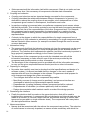
B.2.a The task
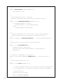
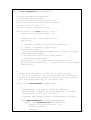
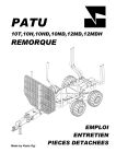
• Our task is to develop an application that models the balloon. The balloon can have
different size and location, both can be controlled by the user by the mean of application
GUI. The balloon (given its size and location) is displayed as a red circle on the blue
background. The application must look similar to the following:
12
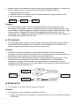
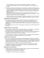
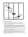
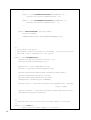
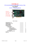
B.2.b The scenario
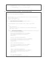
• The scenario for the application can be expressed using the following block-diagram.
• The cycle starts from processing the user input. Application determines the action, after
which it updates balloon size or location, and redraws the playground and the balloon on
the screen as shown in the following block-diagram:
13
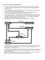
B.2.c The component identification
• The application (namely PlayBalloon) will be composed upon the balloon model, its
view and its controller. These components are dictated to us by the design architecture
we have chosen.
• Balloon is modeled as an object that has position in a virtual world and size. The balloon
is viewed as a red circle on a blue playground.
• The view for the balloon will be an independent from the model visual component
(namely BalloonView) that is displayed in the application window.
• The controller for the balloon (BalloonController) will be able to change the position
and the size of the balloon. The controller will have own GUI (implemented as a separate
class BalloonControlPanel) shown as six buttons: four to alter balloon location in
respective direction and two to alter the balloon size.
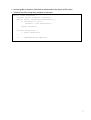
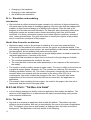
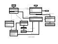
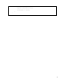
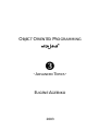
• This architecture can be illustrated using the following UML class diagram:
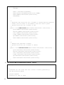
• Considering the above components, the scenario can be illustrated using the UML activity
diagram with swimming lanes. The swimming lanes illustrate what actions are in the
responsibility of which component.
• Rounded boxes in the diagram represents the activities, and rectangular boxes represent
the parameters that result from the previous activity and must be used as an argument for
the successive activity
• Note: in this diagram, the arrows do not mean the invocation calls; rather they mean the
course of action and the order of their execution (and nothing else).
14
The UML activity diagram
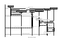
B.2.d The component design
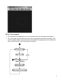
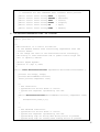
• The following two diagrams illustrate the design of the software components.
• First diagram is a UML class diagram representing static relationship such as
inheritance – a class extending another class – solid arrow with triangle-head, arrow
drawn in direction to super-class
aggregation – object of this class owns one/several/many objects of associated class –
represented as solid arrows with diamond (which can be further classified to either
composite aggregation (solid diamond) or shared aggregation (empty diamond).
Composite aggregation occurs when associated class makes sense ONLY in the
context of the referencing class and makes no sense on its won (e.g. event processing
adapter class or inner class, or role in a club);
other associations – object references another object, which is necessary for method
invocations – represented as normal arrows; arrow is draw in direction of navigability of
the association (can be bidirectional as well)
• Another diagram is a UML sequence diagram representing object lifetime and
communication between objects. Diagram depicts object creation, synchronous and
asynchronous message passing (method invocation operations). Asynchronous method
invocation result for example from event generation or repaint requests and is depicted
as arrows with half-winged arrowhead.
15
Applet
Panel
+init()
PlayBalloon
-myControlPanel
-myBalloon : SimpleBalloon
-myView : BalloonView
-myController : BalloonController
-myControlPanel : BalloonControlPanel
+main(in argv : String[])
+new()
+init()
1
1
1
1
BalloonControlPanel
-grow : Button
-shrink : Button
-left : Button
-right : Button
-up : Button
-down : Button
+new(in controller : BalloonController)
+addListener(in listener : BalloonActionListener)
+removeListener(in listener : BalloonActionListener)
1
-myController
BalloonController
#balloon : BalloonModel
#view : BalloonView
-moveStep : int = 5
-zoomStep : int = 5
+new(in balloon : BalloonModel, in view : BalloonView)
+actionPerformed(in event : ActionEvent)
1
1
1
-myBalloon
SimpleBalloon
-myView
BalloonView
-Location : Point
-Radius : int
+new(in location : Point, in radius : int)
+getLocation() : Point
+getX() : int
+getY() : int
+setLocation(in translate : Point)
+setSize(in zoom : int)
Button
1
6
«uses»
registers to receive action events
«interface»
BalloonActionListener
+GROW() : String = "Grow"
+SHRINK() : String = "Shrink"
+LEFT() : String = "Left"
+RIGHT() : String = "Right"
+UP() : String = "Up"
+DOWN() : String = "Down"
#balloon : BalloonModel
represents
1
1
+new(in balloon : BalloonModel)
+paint(in g : Graphics)
+update(in g : Graphics)
+display()
1
«interface»
ActionListener
+actionPerformed(in event : ActionEvent)
Canvas
+paint(in g : Graphics)
-balloon
asks to redraw
1
BalloonModel
+getX() : int
+getY() : int
+getSize() : int, abstract
+setLocation(in x : int, in y : int)
+setSize(in size : int)
+translate(in translate : Point)
+grow(in zoom : int)
Component
+repaint()
+paint(in g : Graphics)
#balloon
-balloon
1
changes size and location
1
UML class diagram
myApp : PlayBalloon
init()
new(location, radius)
myBalloon : SimpleBalloon
new(myBalloon)
myView : BalloonView
new(myBalloon, myView)
myController : BalloonController
new()
new(myController)
myCotrollerPanel : BalloonControlPanel
addListener(myController)
aButton
addActionListener(myController)
User clicks a button
generates action event
actionPerformed
Computes translate or
zoom parameters
{OR}
[moving]: translate(x:int, y:int)
[zooming]: grow(zoom:int)
repaint()
paint(g)
X:=getX()
Returns control to the system
Y:=getY()
Size:=getSize()
Draws background
and balloon
Returns control to the system
UML sequence diagram
• In order to minimize coupling between components we perform the following steps:
We further split the balloon model into two classes: an abstract BalloonModel and its
implementation as SimpleBalloon (in order to make controller and view independent
on particular balloon implementation).
We let application to have own independent GUI for the controller
(BalloonControlPanel) in order to ease further changes for it.
We make BalloonControlPanel independent from the BalloonController
class by referencing it to an interface BalloonActionListener that defines action
commands and actionPerformed method (via ActionListener interface). The
controller implements this interface in order receive action commands from the GUI.
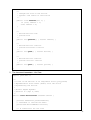
B.2.e The implementation
• The following shows the source code in Java language.
• The source code is supplied with the documentation (javadoc) comments.
1. The class BalloonModel – abstract class for the balloon models
import java.awt.Rectangle;
/**
* Balloon - model for the balloon
* it has size and location as well as utilitary methods
* to change location and size in an imaginable world
*
* @author Eugene Ageenko
* @version 0.1 (Apr 9, 2003)
*/
public abstract class BalloonModel {
/**
* Moves balloon to a new location.
* @param x new horizontal coordinate of the balloon
* @param y new vertical coordinate of the balloon
*/
abstract public void setLocation(int x, int y);
/**
* Changes the size of the balloon
* @param r new radius of the balloon
*/
abstract public void setSize(int r);
/**
* Returns balloon location.
* @return horizontal location
*/
abstract public int getX();
/**
* Returns balloon location.
* @return vertical location
*/
abstract public int getY();
/**
* Returns balloon size.
* @return size
*/
abstract public int getSize();
/**
* Moves balloon relative current location
*/
public void translate(int x, int y) {
setLocation(getX() + x, getY() + y);
}
/**
* Grows/shrinks the balloon.
* @param r new radius increment (negative for shrinking)
*/
public void grow(int r) {
setSize(getSize() + r);
}
/**
* Returns the bounding #Rectangle of this balloon.
*/
public Rectangle getBounds() {
return new Rectangle(getX()-getSize(), getY()-getSize(),
getSize()*2, getSize()*2);
}
/**
* Tests if a specified point is inside the boundary of this
* Balloon
* @param x,y the coordinates to test
* @return <code>true</code> if the specified point
* is contained in the balloon (assumes balloon is a circle);
* <code>false</code> otherwise.
*/
public boolean contains(int x, int y) {
if (getSize() <= 0)
return false;
else
return ((getX() - x) * (getX() - x) +
(getY() - y) * (getY() - y))
< (getSize() * getSize());
19
}
}
2. The class SimpleBalloon – implements balloon model with integral size and location
/**
* SimpleBalloon - model for the balloon that
* has integral size and location
*
* @author Eugene Ageenko
* @version 0.1 (Apr 9, 2003)
*/
public class SimpleBalloon extends BalloonModel {
/** Ballon has radius and central point */
private int radius;
private int xCoord;
private int yCoord;
/**
* Deafult constructor.
* Creates balloon with default parameters: (5,5,5)
*/
SimpleBalloon() {
this(5,5,5);
}
/**
* Parameterized constructor for class balloon
* @param radius balloon radius
* @param x new horizontal coordinate of the balloon
* @param y new vertical coordinate of the balloon
*/
SimpleBalloon(int
this.radius =
this.xCoord =
this.yCoord =
}
radius, int x, int y) {
radius;
x;
y;
/**
* Moves balloon to a new location.
* @param x new horizontal coordinate of the balloon
* @param y new vertical coordinate of the balloon
*/
public void setLocation(int x, int y) {
xCoord = x;
yCoord = y;
}
20
/**
* Changes the size of the balloon
* @param r new radius of the balloon
*/
public void setSize(int r) {
if (r>0) radius = r;
else radius = 0;
}
/**
* Returns balloon size.
* @return size
*/
public int getSize() { return radius; }
/**
* Returns balloon location.
* @return horizontal location
*/
public int getX() { return xCoord; }
/**
* Returns balloon location.
* @return vertical location
*/
public int getY() { return yCoord; }
}
3. The class BalloonView – the View.
import java.awt.*;
/**
* A view of the Balloon in an imaginable world (playground)
* Implemented as blue canvas (Panel) with red circle
* representing the balloon
*
* @author Eugene Ageenko
* @version 0.1 (Apr 9, 2003)
*/
public class BalloonView extends Canvas {
private Dimension preferredSize;
// reference to the balloon model
protected BalloonModel balloon;
/** A constructor for the view
21
* @param b reference to the Balloon
*/
public BalloonView (BalloonModel b) {
this.balloon = b;
}
/**
* Sets preferred size for the view.
* @param d preferred size referenced as Dimension object.
*/
public void setPreferredSize(Dimension d) {
if (preferredSize == null)
preferredSize = new Dimension(d);
else
preferredSize.setSize(d);
}
/**
* Returns preferred size for the view. Use by layout manager.
* @return preferred size referenced as Dimension object.
*/
public Dimension getPreferredSize() { return preferredSize; }
/**
* Move balloon to the center of the playground.
*/
public void centerBalloon() {
Dimension dim = getSize();
balloon.setLocation(dim.width/2, dim.height/2);
repaint();
}
/** Returns a reference to a balloon */
public final BalloonModel getBalloon() { return balloon; }
/**
* Draw playground and balloon.
*/
public void paint(Graphics g) {
// Canvas automatically fills with the current background
// g.clearRect(0, 0, getSize().width, getSize().height);
// Draw balloon
g.setColor(Color.red);
int x = balloon.getX();
int y = balloon.getY();
22
int r = balloon.getSize();
g.drawOval(x - r, y - r, r*2-1, r*2-1);
// g.fillOval(x - r, y - r, r*2, r*2);
}
}
4. The class BalloonControlPanel – the GUI for the controller
import java.awt.*;
import java.awt.event.ActionEvent;
/**
* BalloonControl is a Control Panel with GUI to control the Balloon
* @author Eugene Ageenko
* @version 0.1 (Apr 9, 2003)
*/
public class BalloonControlPanel extends Panel {
private Button grow, shrink, left, right, up, down;
/**
* The constructor.
* @param controller the listener for the events generated by
* the control panel
*/
public BalloonControlPanel(BalloonActionListener controller) {
grow = new Button("Grow");
grow.setActionCommand(controller.GROW);
grow.addActionListener(controller);
add(grow);
shrink = new Button("Shrink");
shrink.setActionCommand(controller.SHRINK);
shrink.addActionListener(controller);
add(shrink);
left = new Button("Left");
left.setActionCommand(controller.LEFT);
left.addActionListener(controller);
add(left);
right = new Button("Right");
right.setActionCommand(controller.RIGHT);
right.addActionListener(controller);
add(right);
up = new Button("Up");
up.setActionCommand(controller.UP);
23
up.addActionListener(controller);
add(up);
down = new Button("Down");
down.setActionCommand(controller.DOWN);
down.addActionListener(controller);
add(down);
}
/**
* Registers new controller as a listener to receive Balloon specific
* events (action events on the moment) from the control panel.
* @param controller the listener to add
*/
public void addListener(BalloonActionListener controller) {
grow.addActionListener(controller);
shrink.addActionListener(controller);
left.addActionListener(controller);
right.addActionListener(controller);
up.addActionListener(controller);
down.addActionListener(controller);
}
/**
* Removes the specified listener.
* @param controller the listener to remove.
*/
public void removeListener(BalloonActionListener controller) {
grow.removeActionListener(controller);
shrink.removeActionListener(controller);
left.removeActionListener(controller);
right.removeActionListener(controller);
up.removeActionListener(controller);
down.removeActionListener(controller);
}
}
5. The interface BalloonActionListener – defines
import java.awt.event.ActionListener;
/**
* Interface for the class that will listen to events generated by
* the BalloonControlPanel
*
* @author Ageenko
* @version 0.1 (Apr 9, 2003)
*/
24
public interface BalloonActionListener extends ActionListener {
// constants for the commands that listener shall process
public static final String GROW
= "grow";
public static final String SHRINK = "shrink";
public static final String LEFT
= "left";
public static final String RIGHT = "right";
public static final String UP
= "up";
public static final String DOWN
= "down";
}
6. The class BalloonController – the Controller.
import java.awt.event.ActionEvent;
import java.awt.*;
/**
* BalloonControl is a control for Balloon.
* It can handle events from controlling components from the
* Control Panel.
* It can change the state of the associated balloon accordingly,
* and finally it asks associated view to update itself trough the
* call to repaint() method.
*
* @author Eugene Ageenko
* @version 0.1 (Apr 9, 2003)
*/
public class BalloonController implements BalloonActionListener {
private int mstep, zstep;
private BalloonModel balloon;
final private Component view;
/**
* The constructor.
* @param balloon balloon model to control
* @param view component representing the view
*/
public BalloonController(BalloonModel balloon, Component view)
{
this(balloon,view,1,1);
}
/**
* The advanced constructor.
* @param balloon balloon model to control
* @param view component representing the view
* @param mstep step for moving when moving button is pressed
* @param zstep step for zooming when zooming button is pressed
25
*/
public BalloonController(BalloonModel balloon, Component view,
int mstep, int zstep)
{
this.balloon = balloon;
this.view = view;
this.mstep = mstep;
this.zstep = zstep;
}
/**
* Event handler. Processes events with action commands specified in
* BalloonActionListener interface
* @see BalloonActionListener
*/
public void actionPerformed(ActionEvent event) {
// System.out.println("Interaction with user");
if (GROW.equals(event.getActionCommand()))
balloon.grow(zstep);
if (SHRINK.equals(event.getActionCommand()))
balloon.grow(-zstep);
if (LEFT.equals(event.getActionCommand()))
balloon.translate(-mstep,0);
if (RIGHT.equals(event.getActionCommand()))
balloon.translate(mstep,0);
if (UP.equals(event.getActionCommand()))
balloon.translate(0,-mstep);
if (DOWN.equals(event.getActionCommand()))
balloon.translate(0,mstep);
// schedules view for the repaint
if (view!=null) view.repaint();
}
}
7. The class PlayBalloon – the application (can work ass applet though).
import
import
import
import
java.applet.Applet;
java.awt.*;
java.awt.event.WindowAdapter;
java.awt.event.WindowEvent;
/**
* Description: Demo application to outline principles of OO Design
* Copyright: Copyright (c) 2002 by author
*
* @author Eugene Ageenko
* @version 0.1
26
*/
public class PlayBalloon extends Applet {
private
private
private
private
private
private
SimpleBalloon myBalloon;
BalloonView myView;
BalloonController myController;
BalloonControlPanel myControlPanel;
final int step = 5;
boolean firsttime = true;
public static void main(String[] args) {
System.out.println("Starting...");
PlayBalloon app = new PlayBalloon();
app.init();
// creating a window to put int the PlayBallon
// applet if running as application
BalloonFrame frame =
new BalloonFrame("Balloon Application, Simple version");
frame.add("Center",app);
// set absolute size for the frame window
// frame.setSize(400,300);
frame.pack(); // let frame window determine its size
app.myView.centerBalloon(); // center balloon in the window
frame.show();
}
/**
* Nested class that defines a frame for the applet allowing
* to run it as application. The cass is defined static because its
* instance not need to be the part of the enclosing class instance.
* This class makes sence only for our Applet class.
*/
static class BalloonFrame extends Frame {
/**
* WindowAdapter is an abstract class that implements
* WindowListener interface. We use WindowAdapter to process
* window events so that we do not need to
* implement every method defined in WindowListener interface.
*/
class MyWindowAdapter extends WindowAdapter {
public void windowClosing(WindowEvent e) {
System.out.println("Closing...");
setVisible(false);
dispose();
27
System.exit(0);
}
public void windowIconified(WindowEvent e) {
System.out.println("Minimized...");
}
public void windowDeiconified(WindowEvent e) {
System.out.println("Restored...");
}
}
public BalloonFrame (String name) {
setTitle(name);
addWindowListener(new MyWindowAdapter());
}
}
/**
* Initializes the applet.
* The method creates instances of the Model, View and Controller
* and adds visual components to the layout.
*/
public void PlayBalloon() {
System.out.println("Initialized...");
setLayout(new BorderLayout());
myBalloon = new SimpleBalloon();
myView = new BalloonView(myBalloon);
myView.setPreferredSize(new Dimension(300,300));
myView.setBackground(Color.blue);
myView.setForeground(Color.black);
add(myView, BorderLayout.CENTER);
myController = new BalloonController(myBalloon, myView,
step, step);
myControlPanel = new BalloonControlPanel(myController);
add("North",myControlPanel);
}
/**
* Place balloon into initial position when applet is started
*/
public void start() {
// center balloon when applet is started
28
if (firsttime) {
myView.centerBalloon();
firsttime = false;
}
}
}
29