1
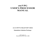
ETA/BSE-in-NX
User’s Manual
Version 2.0
Engineering Technology Associates, Inc.
1133 E. Maple Road, Suite 200
Troy, MI 48083-2896
Phone:+1 (248) 729 3010
Support:+1 (800) 382 3362
Fax:+1 (248) 729 3020
Engineering Technology Associates, Inc., ETA, the ETA logo, and eta/BSE-in-NX are the registered
trademarks of Engineering Technology Associates, Inc. All other trademarks or names are the
property of the respective owners.
©1998-2013 Engineering Technology Associates, Inc. All rights reserved.
ETA/BSE-in-NX 2.0 User Manual
TABLE OF CONTENTS
TABLE OF CONTENTS ................................................................................................................. I
INTRODUCTION ........................................................................................................................... II
1.
FUNCTION INTRODUCTION ...............................................................................................1
1.1 UNFOLD PART.....................................................................................................................1
1.1.1 MATERIAL ....................................................................................................................2
1.1.2 SHEET .............................................................................................................................2
1.1.3 BINDER ..........................................................................................................................5
1.1.4 CONSTRAINT SETTING ..............................................................................................5
1.1.5 AUTO ORIENTATION ..................................................................................................6
1.1.6 ADVANCED SETTING .................................................................................................6
1.1.7 RUN MSTEP ...................................................................................................................8
1.1.8 REPORT ..........................................................................................................................9
1.2 NESTING .............................................................................................................................12
1.2.1 NESTING TYPE ...........................................................................................................17
1.2.2 OPTIMIZATION ..........................................................................................................18
1.2.3 BLANK OUTLINE .......................................................................................................18
1.2.4 PARAMETERS .............................................................................................................18
1.2.5 CONSTRAINT ..............................................................................................................19
1.2.6 COST .............................................................................................................................24
1.2.7 ADVANCED.................................................................................................................25
1.2.8 RESULT ........................................................................................................................27
1.2.9 MANUAL .....................................................................................................................28
1.2.10 REPORT .....................................................................................................................31
1.2.11 CALCULATE 3D TRIMLINE ..................................................................................34
1.2.12 CALCULATE ADDENDUM ....................................................................................34
1.2.13 CALCULATE BRIDGE .............................................................................................35
1.2.14 CREATE BLANK OUTLINE ....................................................................................35
I
ETA/BSE-in-NX 2.0 User Manual
INTRODUCTION
BSE-in-NX consists of two modules: Unfold Part and Nesting. Unfold Part is used for rapid
stamping simulation and will present a Formability Report for the product after solution. In addition,
BSE can be utilized to estimate a blank size and conduct blank development operations, such as blank
fitting and blank nesting. After NX and BSE-in-NX have been installed, the user is allowed to use all
functions of this module in NX.
II
ETA/BSE-in-NX 2.0 User Manual
1. FUNCTION INTRODUCTION
BSE-in-NX consists of two modules: Unfold Part and Nesting. Unfold Part is primarily used to
quickly assess formability and estimate the blank outline in the early stage of automobile body design
and development cycle. Nesting module enables the user to nest the original blank in a coil.
It will generate an eta.log file on the desktop after the user installs this production. The user needs to
obtain the license file and place the license file into the startup directory before using these two
modules. The default path for the startup directory is: C:\Program Files\ETA\BSE-in-NX2.0\startup.
The methods for obtaining the access file are as follows: Contact with the product sales together with
eta.log file, or send the eta.log file directly to [email protected].
1.1 UNFOLD PART
MSTEP is the Modified-One-Step solver developed by ETA. It provides an option for an iterative onestep solution intended to achieve more accurate result with slightly longer computational time than a
conventional one-step solution. It is primarily used to quickly assess formability and estimate the
blank outline in the early stage of automobile body design and development cycle. The Unfold Part
interface is illustrated in Figure 1.1.
Figure 1.1 Unfold Part interface
1
ETA/BSE-in-NX 2.0 User Manual
1.1.1 MATERIAL
It enables the user to define material type and blank thickness. After clicking the Material button, the
material library GUI illustrated in Figure 1.2 is displayed.
Figure 1.2 Material Library dialog box
The user is allowed to select the Standard, Category and Strength Level. The corresponding materials
will be listed in the material name list and the user is allowed to select the corresponding material in
the list.
Standard: There are three types of standard material libraries and they are United States,
China, and Japan.
Category: There are two types of material categories: Steel and Aluminum.
Strength Level: The material library allows the user to classify the following steel grades:
Low, Medium, High, Advanced High, Hot Roll and Cold Roll.
Thickness: The user shall key in the desired blank thickness with mm as its unit.
1.1.2 SHEET
Click the Define Sheet button to display the Class Selection dialog box as illustrated in Figure 1.3,
and the user is allowed to select the corresponding surface through this dialog box. Click the OK
button to confirm the selection and exit the dialog box. The program will automatically mesh the
surface after the sheet has been defined.
2
ETA/BSE-in-NX 2.0 User Manual
Figure 1.3 Class Selection dialog box
Check Surface: Toggle on this option, the program will automatically check if there is the
interference for the defined tool surface. If there is the interference face, it will be highlighted, and a
message box will be popped up to prompt the user with the amount of the interference face. The
Check Surface dialog box is illustrated in Figure 1.4.
Figure 1.4 Check Surface dialog box
Mesh Display: This option will be activated after the sheet has been defined, as illustrated in Figure
1.5. Toggle on this option to display the tool mesh.
3
ETA/BSE-in-NX 2.0 User Manual
Figure 1.5 Sheet Mesh
Mesh Parameter: Click this button to display the Mesh Parameter, as illustrated in Figure 1.6. The
user is enabled to modify the mesh parameters in this window as needed. The mesh will be
automatically updated after the parameters have been confirmed.
Figure 1.6 Mesh Parameter
4
ETA/BSE-in-NX 2.0 User Manual
1.1.3 BINDER
This function is used to define the binder. Flat and Curve represent the plate binder and curve binder
respectively. The default option is Flat. The user is enabled to modify the binder type as needed. If the
Curve option is selected, the Define Curve Tool button and Tool Display option will be activated, as
illustrated in Figure 1.7.
.
Figure 1.7 Tool Definition
Define Curve Binder
Click the Define Curve Binder button to display the Class Selection dialog box illustrated in
Figure 1.3. The user is allowed to select the surface as the curve tool.
Tool Mesh Display
Toggle on this option to display the defined curve tool mesh.
1.1.4 CONSTRAINT SETTING
The constraint setting interface is illustrated in Figure 1.8. Presently, three types of constraints are
supported: Fixed, XZ Symmetry and YZ Symmetry. After selecting the constraint type, the user clicks
the Create button to display the dialog box shown in Figure 1.9. The user is allowed to select the
constraint point or line. After the definition is completed, the user can click the OK button to exit. All
defined constraints will be listed in the constraint list. When the user selects one of the constraints, the
corresponding constraint point will be highlighted in the graphical area.
5
ETA/BSE-in-NX 2.0 User Manual
Figure 1.8 Constraints dialog box
Figure 1.9 Select Constraints
1.1.5 AUTO ORIENTATION
This option is selected by default. In this case, the program will adjust the tipping direction
automatically to fit the MSTEP solver for a good result. If users have adjusted the tipping
direction to the +Z direction manually, a good result can also be got by toggling off this option.
Note: The direction is adjusted only in program, and the direction for original model and mesh
will not be adjusted.
1.1.6 ADVANCED SETTING
Click this button to display the MSTEP Advanced dialog box shown in Figure 1.10.
6
ETA/BSE-in-NX 2.0 User Manual
Figure 1.10 MSTEP Advanced dialog box
ANALYSIS METHOD
The Analysis Method provides two ways for MSTEP: Accurate and Fast. The user can obtain the
calculation results as required according to different methods and parameter settings.
Accurate
This function allows the user to perform MSTEP on blank with the accurate finite element inverse
approach (one-step method). If the user selects this option, the Force and Control Parameter
options will be enabled for the user to define parameters such as Binder and/or Pad holding force,
convergence tolerance and Restraint Condition.
Fast
This function allows the user to perform MSTEP on part with elastic method. If the user selects
this option, the Force and Control Parameter will not be enabled.
FORCE
This option allows the user to set for the force, including binder hold and pad hold.
Binder Hold: Define amount of blank holder force. The default blank holder force is 20000
Newton.
Pad Hold: Define amount of pad force. The default pad force is 20000 Newton.
7
ETA/BSE-in-NX 2.0 User Manual
CONTROL PARAMETER
This option allows the user to define iteration steps, displacement convergence, friction and restraint
condition.
Max. Iteration Steps: Define the Max. Iteration steps during calculation. The default max
iteration steps is 200.
Disp. Convergence: Define the displacement convergence for calculation. The default
displacement convergence is 1.0e-003.
Friction: Define the friction between the blank and tools. The default friction is 0.125.
RESTRAINT CONDITION
This option allows the user to adjust the restraint condition applied on boundary. This option is only
available for Accurate solving, as illustrated in Figure 1.11.
Figure 1.11 Constraint Condition setting
When this option is available, the boundary will be highlighted. The Medium is default for all the
boundaries, and it allows the user to adjust the restraining force by selecting the Type or dragging the
scroll bar.
1.1.7 RUN MSTEP
After defining the tool, the Run Mstep button will be activated. Click this button and the user can
submit the current setting to solver for calculation. After the completion of calculation, the program
will automatically import the created blank outline, preparing for the subsequent analysis.
Note 1: If there is no result after running MSTEP, the message window as illustrated in Figure 1.12
will be displayed. At this time, the user should check the model to insure the model is right.
Note 2: After Mstep is run to generate the outline result, it will create the temporary file named UGIIUGII-ANON-1.prt in the file directory, and this file can be deleted optionally.
Figure 1.12 Message Window
8
ETA/BSE-in-NX 2.0 User Manual
1.1.8 REPORT
This button is only activated after the user uses MSTEP for analysis and solving. After this button is
clicked, the formability report dialog box will be popped, as illustrated in Figure 1.13.
Figure 1.13 Formability report dialog box
POST ANALYSIS OPTION
There is one defining button behind each analysis option, which allows the user to set the scope of
contour for the corresponding analysis option, as illustrated in Figure 1.14.
Figure 1.14 Contour setting dialog box
Thickness: Evaluate the forming quality through thickness of different areas of part.
9
ETA/BSE-in-NX 2.0 User Manual
Thinning: Evaluate the morphing quality through thickness variation.
Thickness Strain: Evaluate the morphing quality through thickness strain.
Major Prin. Strain: Evaluate the morphing quality through major prin. Strain.
Min Prin. Strain: Evaluate the morphing quality through min prin. Strain.
Strain Tensor is used to estimate the morphing quality.
FLD is used to evaluate the formability of blank.
OUTPUT REPORT TYPE
This option offers three report formats: PDF format, JPG format and XLS format.
OPEN POST
Once this option is selected when generating the report, the program will automatically open the
corresponding postprocessor by sequence according to the selection of postprocessor analysis options
and read in the analysis results. The program will open as many postprocessors as the post analysis
options are selected by the user.
VIEW REPORT
This button will be highlighted only after the reported is generated. Click this button to view the
generated report.
VIEW RESULT
This option is only highlighted after the MSTEP submits for calculation. Click this option, and the
program will automatically call the Post-processor of eta/post and read in the result file for the user to
deal with the forming analysis.
Note: ETA/Post is a general post-processor for all ETA software, including DYNAFORM, VPG, FEMB
and BSE-in-NX. POST is an independent application module. The POST module quickly postprocesses result data of finite element analyses, including the real-time animation of stresses,
strain, energy, displacements, and time history curves. Its fully dynamic allocation of memory
optimizes system resources, allowing for unlimited model sizes.
APPLY
This button will be activated only after the user uses MSTEP for analysis and solving. Clicking this
button will cause the program to automatically use the postprocessor to read in the .dynain file, show
the results from four different angles in the report according to different postprocessor analysis options,
and mark the maximum and minimum values of contour results on the part model, as illustrated in
Figure 1.15.
10
ETA/BSE-in-NX 2.0 User Manual
Figure 1.15 Formability Report (PDF)
Cancel
Click this button to exit the MSTEP dialog box.
11
ETA/BSE-in-NX 2.0 User Manual
1.2 NESTING
Note: After opening Nesting module, it will create the temporary file named *.nest in the prt file
directory, and this file can be deleted optionally.
This function enables the user to nest the original blank in a coil, and the interface is illustrated in
Figure 1.16.
Figure 1.16 NX Nesting interface
Figure 1.17 shows the types of nesting options available in the Nesting menu.
Figure 1.17 Nesting types
12
ETA/BSE-in-NX 2.0 User Manual
ONE-UP NESTING
It enables the user to generate the nesting result in one row.
Figure 1.18 One-up Nesting
TWO-UP NESTING
It enables the user to generate the nesting result with two identical blanks using a common orientation.
Figure 1.19 Two-up Nesting
13
ETA/BSE-in-NX 2.0 User Manual
TWO-PAIR NESTING
It enables the user to generate the nesting result with a pair of identical blanks in opposite orientation.
Figure 1.20 Two-pair Nesting
MIRROR NESTING
It enables the user to generate the nesting result by mirroring the blank.
Figure 1.21 Mirror Nesting
14
ETA/BSE-in-NX 2.0 User Manual
MULTITI NESTING
It enables the user to generate the nesting result using multiple blanks with different size and shape.
Figure 1.22 Multiple Nesting
RECTANGLE NESTING
It enables the user to generate the nesting result by embedding the blank in rectangle.
Figure 1.23 Rectangle Nesting
PARALLEL NESTING
It enables the user to generate the nesting result by embedding the blank in parallelogram.
15
ETA/BSE-in-NX 2.0 User Manual
Figure 1.24 Parallel Nesting
ISOSCELES TRAPEZOID NESTING
It enables the user to generate the nesting result by embedding the blank in isosceles trapezoid.
Figure 1.25 Isosceles-Trapezoid Nesting
TRAPEZOID NESTING
It enables the user to generate the nesting result by embedding the blank in trapezoid.
Figure 1.26 Trapezoid Nesting
ARC NESTING
It enables the user to generate the nesting result by embedding the blank in arc.
16
ETA/BSE-in-NX 2.0 User Manual
Figure 1.27 Arc Nesting
Examples of blank nesting are illustrated in Figure 1.18 to Figure 1.27. A detailed description of each
function is given in the following section.
1.2.1 NESTING TYPE
Form Nesting Type
This indicates the nesting functions in the first row in the GUI window, including one-up
nesting, two-up nesting, two-pair nesting, mirror nesting and multi blanks. The user is
allowed to select one of these types for nesting. After the user selects one optimization
target and toggles on this option, all the nesting functions in the first row except multiblanks will be highlighted. The program will automatically calculate all the highlighted
nesting types and save the calculation results corresponding to each nesting type in the
result list for the user to browse and compare the difference.
Draw Nesting Type
This indicates the nesting functions in the second row in the GUI window, including
rectangle nesting, parallel nesting, isosceles-trapezoid nesting, trapezoid nesting and arc
nesting. The user is allowed to select one of these types for nesting. After the user has
selected one optimization target and toggled on this option, all the nesting functions in the
second row will be highlighted. The program will calculate all the nesting types in the
second row, and save the calculation results corresponding to each nesting type in the result
list for the user to browse and compare the difference.
17
ETA/BSE-in-NX 2.0 User Manual
1.2.2 OPTIMIZATION
There are two types of nesting optimization, as illustrated in Figure 1.28. One is to use the material
utilization as optimization target to maximize the use of coil. The other is to use the material for
nesting as optimization target to minimize the coil price for nesting. The user can select either
optimization type as the target to achieve the desired result.
Figure 1.28 Optimization type
Max. Utilization
This is a commonly used optimization type, which is to maximize the material utilization in
the nesting process.
Min. Cost
The coils used for nesting have different costs. During nesting calculation, besides the
material utilization, the production cost will also be considered so that the material cost
could be minimized for nesting. Once this option is toggled on, the Cost button will be
enabled.
1.2.3 BLANK OUTLINE
After the Blank Outline (Undefined) button is clicked, it will display the Select Blank Outline dialog
box shown in Figure 1.29, which prompts the user to select one or a group of closed outline to define
blank outline.
Figure 1.29 Select Outline dialog box
Note: After the Blank Outline is defined, the button name is changed to Blank Outline.
1.2.4 PARAMETERS
This function is used to set various parameters for the nesting, including the Edge Width, Bridge Span,
Addendum and Feed Scrap. The interface is illustrated in Figure 1.30.
18
ETA/BSE-in-NX 2.0 User Manual
Figure 1.30 Nesting Parameters
Edge Width
This option allows the user to define the gap between blank outline and coil edge. The
default value is 2.
Bridge Span
This option allows the user to define the gap between parts. The default value is 5.
Addendum
This option allows the user to expand the selected blank outline. The default value is zero.
Feed Scrap
For the progressive press part, the user can define the feed scrap required for nesting and
mark on the nesting result drawing. The default value is zero.
The parameters are shown in Figure 1.31.
Figure 1.31 Edge Width, Bridge Span and Addendum
1.2.5 CONSTRAINT
This function enables the user to constrain the dimension of the coil and the angle of blank relative to
the coil direction. The tab is illustrated in Figure 1.32 and Figure 1.33.
19
ETA/BSE-in-NX 2.0 User Manual
Figure 1.32 Coil Constraint
Figure 1.33 Plate Constraint
20
ETA/BSE-in-NX 2.0 User Manual
DIMENSION
It allows the user to operate nesting for the coil or plate. The program will automatically constrain the
nesting results according to different blanks selected.
LENGTH
After the Coil is selected, Fix Length is used to constrain the coil length. If the inner diameter (ID)
and outer diameter (OD) are defined, the user is allowed to calculate the length by clicking the
Calculator button.
After the Plate is selected, the user may enter a plate length value to constrain the nesting
drawing. The value will be marked on the nest defining result drawing.
CALCULATOR
Click on the
button, and the Calculator dialog box will be displayed, as illustrated
in Figure 1.34. After the inner diameter (ID) and outer diameter (OD) values are selected, the coil
length will be displayed in the Length field.
Figure 1.34 Calculator dialog box
WIDTH
After the plate is selected, the user may enter a sheet width value to constrain the nesting
drawing. The value will be marked on the nest defining result drawing.
Note: This function is available only when the blank type is Plate.
WEIGHT
The program will automatically calculate the blank weight (kg) according to the previouslydefined parameters .
Note: This function is available only when the blank type is Plate.
BLANK OPTION
Fix Angle is used to specifically define a constant rotation angle.
21
ETA/BSE-in-NX 2.0 User Manual
Fix Pitch is used to specifically define a constant pitch.
Fix Width is used to specifically define a constant width.
Width >Pitch: During nesting, width is greater than pitch. This option will automatically change
to Width >Pitch*0.5 to constrain part when the user selects Two Pair, Mirror, Isoscelestrapezoid and Trapezoid.
In One Row: This option is available only for Mirror. During nesting, the nesting drawing is
constrained and the nesting result is listed in one row.
ALIGN OPTION
Note: This option is only enabled in plate nesting.
Center: When this option is selected, the nesting result will be located in the center of the blank.
Up: When this option is selected, the nesting result will be located near the top of the blank.
Left: When this option is selected, the nesting result will be located near the left of the blank.
Use Fall Off: When this option is selected, the program will improve the material utilization as
much as possible through two different nesting styles,
BLANK RANGE
This button is used to show or hide the range option and cut-off die option. When this button is click,
the range option and cut-off die option will be displayed, as illustrated in Figure 1.35 (a) and Figure
1.35(b).
22
ETA/BSE-in-NX 2.0 User Manual
(a)Coil
(b)Plate
Figure 1.35 Complete dialog box in Constraint
RANGE OPTION
This option uses the range values to constrain the parameters such as rotation angle, width, pitch, cutoff profile angle, and cut-off profile arc radius.
ANGLE
Min./Max.: Use an angle with a certain range to constrain the blank rotation and blank width.
After entering the minimum and maximum values of angle, blank nesting calculates a series of
results according to the defined range of the rotation angle.
WIDTH
Constrain the width of the coil or sheet.
Min./Max.: The width range is used as the width constraint. The user defines the allowable
range of the blank width (Min and Max). Blank nesting calculates a series of results according to
the defined range of the width.
PITCH
23
ETA/BSE-in-NX 2.0 User Manual
Constrain the pitch value during nesting.
Cut-off die
L Angle: The angle between the left side of parallelogram, isosceles trapezoid and trapezoid with
the positive direction of X-Axis. Use an angle value within a certain range to constrain the shape
of the parallelogram, isosceles trapezoid and trapezoid profiles. After entering the minimum and
maximum values of angle, blank nesting calculates a series of results accordingly.
R Angle: The angle between the right side of trapezoid and the positive direction of X-Axis. Use
an angle value within a certain range to constrain the shape of trapezoid profile. After entering
the minimum and maximum values of angle, blank nesting calculates a series of results
accordingly.
Radius: The radius of the arc profile. Use an angle value within a certain range to constrain the
shape of arc profile. After entering the minimum and maximum values of angle, blank nesting
calculates a series of results accordingly.
1.2.6 COST
The Cost button can only be enabled when the user selects Min Cost as the optimization type on Setup
page, and it is illustrated in Figure 1.36. The Cost dialog shows the material name and thickness
applied to the outline defined on the Setup page, and provides the list of material. It allows the user to
perform create or delete operations.
Figure 1.36 Cost Page
24
ETA/BSE-in-NX 2.0 User Manual
Material
Material shows the material name defined on Unfold Part page and cannot be modified.
Thickness shows the material thickness defined on Setup page and cannot be modified.
List
In the installation directory folder: ETA\BSE-in-NX2.0\tpl\csv, there is a price.csv file which is a table
made according to different thickness and width. The initial price values in the price list are read in
from this file, and the user is may edit this file.
New
allows the user to create a line at the end of the list and enter the width and cost in the
input box illustrated in Figure 1.37. After selecting this icon, the program will
automatically add a new line and the price value is same with the one in the input box.
Figure 1.37 Cost input box
Delete
allows the user to delete any line in the list.
Extra Cost allows the user to accept default or modify the extra material price.
Scrap Cost allows the user to accept default or modify the scrap price.
1.2.7 ADVANCED
This function sorts the seldom-changed parameters together for the user to set up. The user is allowed
to set Parameters, Output Unit, No of Outlines and Decimal digits, as illustrated in Figure 1.38.
Figure 1.38 Advanced Option
25
ETA/BSE-in-NX 2.0 User Manual
PARAMETERS
This function is used to set the Edge Width and Bridge Span. The “By Csv file” options is used to
specify the determination of the initial edge width and bridge span. If the “By Csv file” option is
selected, the parameter will read in from the Csv file.
By Default
This option is selected by default, in this case, the Edge Width is 2 times of material thickness
and Bridge Span is 5 times of material thickness.
By Csv file
This option enables the user to read in the initial edge width and bridge span from the
NestingParameter.csv file which is in the installation directory folder. This file sets the edge
width and bridge span according to the perimeter of the defined outline. It also allows the user to
modify and edit the values.
OUTPUT UNIT
Metric
This option enables the user to define the nesting setup parameters in metric unit.
English
This option enables the user to define the nesting setup parameters in English unit.
NO. OF OUTLINES
This function enables the user to set the number of blank outlines in the nesting result. The default is
three. The user is allowed to select multiple numbers to display from a list.
LENGTH DIGITS
This function enables the user to set the length digits in the nesting result and 0 to 5 decimal digits can
be set. The default is one decimal places.
UTILIZATION DIGITS
This function enables the user to set the utilization digits displayed in the nesting result and 0 to 5
decimal digits can be set. The default is three decimal places.
APPLY
Click the Apply button to calculate the nesting result and show it on the screen according to the
current blank position, as illustrated in Figure 1.39. Only after the user has defined the blank outline
and selected the nesting type, the Apply button can be activated.
26
ETA/BSE-in-NX 2.0 User Manual
Figure 1.39 The Result of One-up Nesting
1.2.8 RESULT
A series of nesting results calculated under constraints are displayed in the list, as illustrated in Figure
1.40.
Note: The user is not allowed to delete the nesting result separately in this version.
Figure 1.40 Nesting result
OUTLINE
Multiple outlines are supported by the program, and the user is allowed to select one of the outlines
from the drop-down list of Outline. The
button is used to delete the selected outline. If the user
selects one outline, and all results corresponding to this outline will be deleted.
RESULT
After selecting the outline and nesting type and clicking the Apply button to generate the nesting
result, the nesting results for all types will be listed in the result list and the user can select any one of
the results from the drop-down list. After selecting the result, all results corresponding to the type will
be displayed in the detail list.
27
ETA/BSE-in-NX 2.0 User Manual
DETAIL LIST
The user may select any type from the result list to display the information corresponding to this type,
such as the angle, width, pitch and utilization.
PROGRESS BAR
The progress bar is activated to display the completion progress of nesting during the nesting
calculation.
1.2.9 MANUAL
This Manual button enables the user to adjust the relative position between two blanks by moving,
rotating, and mirroring the blank. Click on the Manual button to open the Manual dialog box
illustrated in Figure 1.41.
Figure 1.41 Manual nesting interface
X-Y STEP
28
ETA/BSE-in-NX 2.0 User Manual
This function allows the user to set incremental values for the X and Y direction for the
transformation. During the nesting calculation, the program will translate the blank according to the
defined steps within the defined range to obtain a series of results. The default X-Y step is 10.
ANGLE STEP
This is the angle increment for blank rotation. The default angle step is 2 degrees. During the nesting
calculation, the program will rotate the blank according to the defined steps within the defined angle
range to obtain a series of results.
FREE
This option allows the user to adjust the blank flexibly. Toggle on this option to translate and rotate the
blank position flexibly, without considering the interference of other blanks. This option is available
only for One-up Nesting, Two-up Nesting, Two-pair Nesting, Mirror Nesting and Multiple Nesting.
SELECT BLANK
This function allows the user to select master blank and slave blank respectively, to perform
operations such as translation, rotation and mirroring, and adjust the position between blank nesting
for multiple parts nesting manually. Once a blank is selected, the outline of this blank turns to grey.
Since Master Blank mainly controls the pitch size during nesting, the adjusting button can only be
enabled after selecting the Slave Blank option from the list.
TRANSFORMATION
Move selected blank outline in positive X-Axis direction according to incremental distance.
Move selected blank outline in negative X-Axis direction according to incremental distance.
Move selected blank outline in positive Y-Axis direction according to incremental distance.
Move selected blank outline in negative Y-Axis direction according to incremental distance.
ROTATION
Rotate selected blank outline clockwise by incremental angle.
Rotate selected blank outline counter-clockwise by incremental angle.
PARAMETERS
This function is used to show the current parameters, and the user may adjust these values directly.
According to the adjusted parameters, the program automatically calculates and shows the nesting
results, width, pitch and utilization.
L Angle: This option is only available when parallel nesting, isosceles trapezoid nesting, and
trapezoid nesting are selected. It is used to show the current angle when adjusting the cut-off
profile shape.
R Angle: This option is only available when trapezoid cut-off profile nesting is selected. It is
used to show the current angle when adjusting the cut-off profile shape.
29
ETA/BSE-in-NX 2.0 User Manual
Radius: This option is only available when arc nesting is selected. It is used to show the current
radius of arc when adjusting the cut-off profile shape.
Angle: Shows the current angle of blank rotation when adjusting the blank position.
Pitch: The program automatically calculates the nesting result, and shows the current pitch of
blank on coil according to the adjusted blank position and cut-off profile shape.
Width: The program automatically calculates the nesting result, and shows the current width of
blank on coil according to the adjusted blank position and cut-off profile shape.
Utilization: The program automatically calculates the current utilization of blank nesting
according to the adjusted blank position and cut-off profile shape.
RECORD
This function enables the user to record the maximum value of utilization calculated from the adjusted
nesting results. Besides the maximum utilization, the program will also save the corresponding blank
position and cut-off profile shape. Clicking
button, the program will automatically show the
nesting result for the maximum utilization in view area and the dialog box.
OK
Click the OK button to confirm the modified nesting result and exit the Manual dialog box.
CANCEL
Exit the Manual dialog box without any modification.
MANUAL OPERATION
The user is also allowed to adjust the blank and cut-off profile directly in the view area. Click this
button to display the Select Feature points dialog box illustrated in Figure 1.42.
Figure 1.42 Select Feature Points dialog box
There are blue feature points labeled in the center of blank, pitch, width and the side length of cut-off
profile, as illustrated in Figure 1.43. Moving the mouse cursor to the feature point, the program will
show the translation and rotation arrows near the cursor for the user to adjust the blank and cut-off
profile shape directly. The user can click the left mouse button once to start manual operation and
click the left mouse button again to end the manual operation. The user can also adjust them through
manual adjustment buttons in the Manual dialog box. No matter which adjustment method is selected,
the current values of the corresponding parameters will be displayed in the position dialog box during
adjustment.
When the user selects Two-up Nesting, Two-pair Nesting, Mirror Nesting or Multi blanks Nesting,
there are three blue feature points labeled in the center of the master blank, the center of the slave
blank and the center of the two connecting points in the graphic area. The user is allowed to rotate the
master blank, the slave blank, or both master and slave together, maintaining their relative orientation,
and adjust the positions of the master blank and slave blank.
30
ETA/BSE-in-NX 2.0 User Manual
Figure 1.43 Feature points for manual nesting
1.2.10 REPORT
This function enables the user to output the nesting result in htm format. The interface of the Output
Nesting Report is illustrated in Figure 1.44.
Figure 1.44 Nesting Repot dialog box
Click Apply button to output the nesting result. The nesting report will be presented
automatically in .htm format.
DATE
31
ETA/BSE-in-NX 2.0 User Manual
Display date of the nesting report.
FILE NAME
Enable the user to assign a file name (.htm) and the file path to save the current nesting
report.
BLANK OUTLINE COLOR
Enable the user to change color of the blank outline.
OUTPUT UNIT
Display current unit system in nesting report.
PRODUCTION VOLUME / PER COIL
Enable the user to select Production Volume or Per Coil for cost calculation. This option is
unavailable if the blank is plate.
PRODUCTION VOLUME
Enable the user to define production volume. This option is unavailable if the blank is plate.
COIL LENGTH
Display coil length defined in Constraints. This option is unavailable if the blank is plate.
BASE MATERIAL COST
Enable the user to define base material cost.
EXTRA MATERIAL COST
Enable the user to define extra material cost.
SCRAP VALUE COST
Enable the user to define scrap value cost.
CONSUMABLES COST
Enable the user to define consumable cost.
COMMENTS
Enable the user to write comments in the nesting report.
A typical nesting report is illustrated in Figure 1.45.
32
ETA/BSE-in-NX 2.0 User Manual
Figure 1.45 Nesting Report example
33
ETA/BSE-in-NX 2.0 User Manual
YIELD RATIO
Different from the nesting utilization, this option is the ratio between the Product Weight
and Pitch * Width.
In the nesting report, the values in Product Weight option and Yield Ratio option can only be
output after the user submits the 3D product to estimate the outline, excluding the tailorwelded blank parts.
NET WEIGHT/BLANK
After the user has run MSTEP for the outline estimation, the program will automatically
calculate the weight of 3-dimension blank according to the dimension of the generated
OUTLINE and the density and thickness of the defined material.
GROSS WEIGHT/BLANK
The program will automatically calculate the width and pitch of different nesting type
according to the produced OUTLINE. The program will automatically calculate the gross
weight of the product according to the envelope area produced with width and pitch and the
density and thickness of the defined material.
FALL OFF WEIGHT/BLANK
The scrap weight is the gross weight minus the net weight.
1.2.11 CALCULATE 3D TRIMLINE
This button is only activated when the user uses MSTEP and selects Draw Nesting Type for pitch
scaling. To automatically project the adjusted 2D line onto the 3D product part, the user should select
one result of the nesting calculation and click Calculate 3D Trim Line button. The user can view the
3D projection line on the part after exiting the Nesting dialog box.
1.2.12 CALCULATE ADDENDUM
This button is only activated when the user selects Draw Nesting Type. Click the Calculate Addendum
button to display the dialog box illustrated in Figure 1.46.
Figure 1.46 Calculate Addendum dialog box
Compensating Rate
Compensating rate is used to calculate a coefficient of addendum, and the default is 0.8. The user
34
ETA/BSE-in-NX 2.0 User Manual
is allowed to modify the value,.
Addendum
The program can automatically calculate an appropriate addendum according to the empirical
formula by empirical formula according to the current nesting result (Pitch and Width) and
compensating rate. The user is not allowed to modify the addendum value.
Click the OK button to obtain an appropriate Addendum value. Click the Cancel button to exit this
dialog box. The program will automatically put the calculated addendum on the Setup page for the
user to redo the nesting calculation according to this addendum.
1.2.13 CALCULATE BRIDGE
This button can only be activated when the user selects One-up Nesting. This option is mainly used to
maximize the material utilization. Click Calculate Bridge button to display the dialog box illustrated in
Figure 1.47.
Figure 1.47 Calculate Bridge
Compensating Rate
Compensating rate is used to calculate a coefficient used to determine the bridge size, and the
default is 0.9. The user is allowed to modify the value.
Bridge
The program can automatically calculate an appropriate bridge value by the empirical formula for
compensation according to the current nesting result (Edge Width) and compensating rate. The
user is not allowed to modify the bridge value.
Click the OK button to obtain an appropriate Bridge value. Click the Cancel button to exit this
dialog box. The program will automatically redo the nesting calculation after applying the new
bridge value. The nesting result will be updated accordingly.
1.2.14 CREATE BLANK OUTLINE
This button is only available when the user selects the second row in Draw Nesting Type. By clicking
the Create Blank Outline button, the program will automatically generate blank outline according to
the currently selected Draw Nesting Type, including rectangle, parallelogram, trapezoid, isoscelestrapezoid, and arc outline. The user can view it after exiting the nesting dialog box.
35