1
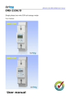
DRS-201 series User Manual WARNING Installation should be performed by qualified personnel familiar with related procedures and regulations. Use insulating tools to install the meter. Fuse or thermal cut-off or single-pole circuit breaker can’t be fitted on the supply line and not the neutral line. The case is sealed, do not broken it We recommend that the connecting wire which is used to connect the meter to the outside circuit should be sized according to local codes and regulations for the capacity of the circuit breaker or over current device used in the circuit. An external switch or a circuit-breaker should be installed on the inlet wire, which will be used as a disconnection device for the meter. And there it is recommended that the switch or circuit-breaker is near the meter so that it is more convenience for the operator. The switch or circuit-breaker should comply with the specifications of the building electrical design and all local regulations. An external fuse or thermal cut-off which will be used as a over-current protection device for the meter must be installed on the supply side wire, and it is recommended that the over-current protection device is near the meter so that it is more convenience for the operator. The over-current protection device should comply with the specifications of the buildings electrical design and all local regulations. This meter can be installed indoor directly, or in a meter box which is waterproof outdoor, subject to local codes and regulations. To prevent tampering, secure the meter with a padlock or a similar device. The meter has to be installed against a wall which is fire resistant. The meter has to be installed in a good ventilated and dry place. The meter has to be installed in a protection box when placed in dangerous or dusty environment. The meter can be installed and used after being tested and sealed with a letter press printing. The meter can be installed on a 35mm DIN rail. The meter should be installed in an available height so that it is easy to read. When the meter is installed in an area with frequent surges due to e.q. thunderstorms, welding machines, inverters etc, protect the meter with Surge Protection Devices. After finishing installation, the meter must be sealed to prevent tampering. Connection of the wires should be done in accordance with the underneath connection diagram. 1 4 3 6 20 and 21 Inlet phase line Inlet neutral line Outgoing phase line Outgoing neutral line Pulse output contact 1.9 Operating Shanghai Fengyilong Electronic CO.LTD. www.china-meters.com Email:[email protected] 86-21-60975591/ 60975592