1
USER'S MANUAL
CONTROL BOARD
MODEL
Rev. 1.00
BD2-2820
Nov. 06,1996
Japan CBM Corporation
Information Systems Div.
<CAUTIONS>
1. Before using this equipment, be sure to read this User's manual thoroughly.
Please keep this with care so as to referred to any time at need.
2. Portions of the contents of this User's manual may be changed without prior notice.
3. The reproduction of parts or all of the contents of this User's manual without permission is strictly
forbidden.
4. Absolutely do not carry out maintenance, disassembly, or repair of parts that are not specified
in this User's manual.
5. Note that losses which may be attributed to the user's wrong operation method or operating environment
will be outside the responsibility of this company.
6. Do not carry out the operations other than those explained in this User's manual,
since doing do so may become a cause of accidents or breakdowns.
7. Because data is basically transient, long-period and permanent storage of data will not be possible.
Please note in advance that this company will not be responsible in any way for losses or lost profits
caused through the clearing of the data due to breakdowns, repairs, investigations, etc.
8. If any questionable points, mistakes, omitted explanations, etc. are found in the contents of
this manual, please contact this company.
9. Please note that notwithstanding the conditions in above 8, this company will not be responsible
for the consequences of results obtained through operation of this equipment.
2
CONTENT
1. OUTLINE ............................................................................................................................................ 4
1.1 FEATURES ................................................................................................................................... 4
1.2 PRECAUTION.............................................................................................................................. 4
2. BASIC SPECIFICATIONS ................................................................................................................. 4
2.1 MODEL CLASSIFICATION ....................................................................................................... 4
2.2 BASIC SPECIFICATIONS .......................................................................................................... 5
3. CONNECTING CONNECTORS........................................................................................................6
3.1 CN 1 ..............................................................................................................................................6
3.2 CN 2 ............................................................................................................................................6
3.2 CN 3 ............................................................................................................................................6
3.4 CN 4 ............................................................................................................................................7
3.5 CN 5 ............................................................................................................................................8
3.6 CN6 .............................................................................................................................................9
4. DIP SWITCH SETTING ...................................................................................................................10
5. POWER SUPPLY ..............................................................................................................................12
5.1 SPECIFICATIONS .....................................................................................................................12
5.2 PRECAUTION ...........................................................................................................................12
6. PARALLEL INTERFACE ................................................................................................................12
6.1 SPECIFICATIONS ........................................................................................................................12
6.2 EXPLANATION OF INPUT/OUTPUT SIGNALS ......................................................................12
6.3 ELECTRICAL CHARACTERISTICS ..........................................................................................13
6.4 TIMING CHART ...........................................................................................................................14
6.5 DATA RECEIVING CONTROL ..................................................................................................14
6.6 BUFFERING ..................................................................................................................................14
7. SERIAL INTERFACE .......................................................................................................................15
7.1 SPECIFICATIONS ........................................................................................................................15
7.2 EXPLANATION OF INPUT/OUTPUT SIGNALS ......................................................................15
7.3 DATA CONFIGURATION ...........................................................................................................16
7.4 ERROR DETECTION ...................................................................................................................16
7.5 DATA RECEIVING CONTROL ..................................................................................................16
7.6 BUFFERING ..................................................................................................................................16
7.7 ELECTRICAL CHARACTERISTICS ..........................................................................................17
8. PRINT CONTROL FUNCTION .......................................................................................................18
8.1 COMMAND LIST .........................................................................................................................18
8.2 COMMAND DETAILS .................................................................................................................19
9. CHARACTER CODE TABLE ..........................................................................................................32
9.1 INTERNATIONAL .......................................................................................................................32
9.2 INTERNATIONAL CHARACTER CODE TABLE ....................................................................33
APPENDIX 1 . BLOCK DIAGRAM ..........................................................................................................34
APPENDIX 2 . BASIC DRAWING............................................................................................................35
3
1. OUTLINE
This control boars is designed to be used to control our thermal printer, "LT-282" or "LT-283" series
through the computer etc.
As being provided with many abundant functions, it can be used widely in various applications.
Before you start using it, read this manual thoroughly and understand the content.
1.
FEATURES
(1)
Ultra compact
(2)
Both interface of Serial and Parallel can be selected by dip switch.
(3)
Input buffer incorporated.
(4)
Bar code printing is available.
(5)
Auto paper cutter control incorporated.
(6)
User-defined character registration function (94 characters)
1.1 PRECAUTION
(1) Make sure to turn OFF the power supply in case of connecting / disconnecting the connectors.
(2) Absolutely do not make a short circuit between the terminals of connectors.
(3) Use power supply, LED, interface etc. following their specifications.
2. BASIC SPECIFICATIONS
2.1 Model classification
BD 2- 282 0 U
Character Set
U:International model
Model name of applied printer mechanism
282 : For LT-282 and LT-283
Model name
4
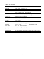
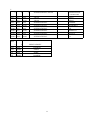
2.2 BASIC SPECIFICATIONS
ITEM
CONTENTS
Print width
56 mm : LT-282 ,
Print Speed
50 mm / s (MAX)
Number of columns
Font A : 37 columns LT-282,
34 columns LT-283
Font B : 49 columns LT-282,
46 columns LT-283
Character dimensions
52 mm : LT-283
Font A : 1.25 mm x 3.00 mm (10x24 dots + 2 dots space)
Font B : 0.88 mm x 2.13 mm ( 7x17 dots + 2 dots space)
Character types
Alphanumeric, international characters
Bar code type
UPC-A/E, JAN (EAN) 13 / 8 columns , ITF
CODE 39, CODE 128, CODABAR
Line pitch
4.23 mm (1/6 inch)
Interface
Parallel (conforms to Centronics) or Serial (conforms to RS-232C)
(Selectable by dip switch)
Input buffer
Supply voltage
4 K bytes or 72 bytes
(Selectable by dip switch)
5V ± 5 % 145 mA (Self printing)
24 V ± 5 % Average 1.8 A (Peak approx. 6 A)
Operating Environment
5 - 40 ℃
Storage Environment
-20 - 60 ℃
Outer Dimension
80 mm (W) x 80 mm(D)
Weight
Approx. 50 g
(For height of component parts, see outer drawing.)
5
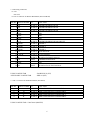
3. Connecting connectors
3.1 CN 1
Not used.
3.2 CN 2 Connector for Printer Mechanism (For Print Head)
PIN NO. SIGNAL NAME I/O
FUNCTION
1 VH
OUTPUT POWER FOR PRINT HEAD
2 VH
OUTPUT POWER FOR PRINT HEAD
3 VH
OUTPUT POWER FOR PRINT HEAD
4 GND
GND
5 GND
GND
6 GND
GND
7 VCC
OUTPUT POWER FOR PRINT HEAD CIRCUIT
8 STRB1
OUTPUT STROBE 1
9 STRB2
OUTPUT STROBE 2
10 STRB3
OUTPUT STROBE 3
11 CP
OUTPUT CLOCK PULSE
12 LATCH
OUTPUT LATCH SIGNAL
13 DI
OUTPUT HEAD DATA INPUT SIGNAL
14 TH
INPUT
15 GND
THERMISTOR SIGNAL
GND
16 DO
INPUT
HEAD DATA OUTPUT SIGNAL
USING CONNECTOR
: B16B-PH-K-S (JST)
APPLICABLE CONNECTOR
: PHR-16 (JST)
3.3 CN 3 Connector for Print Mechanism (For Motor)
PIN NO. SIGNAL NAME I/O
FUNCTION
1
A
OUTPUT OPERATION SIGNAL FOR MOTOR A
2
B
OUTPUT OPERATION SIGNAL FOR MOTOR B
3
A’
OUTPUT OPERATION SIGNAL FOR MOTOR A’
4
B’
OUTPUT OPERATION SIGNAL FOR MOTOR B’
USING CONNECTOR : 53047-0410 (MOLEX)
6
3.4 CN 4 Connector for Print Mechanism (For Sensor)
PIN NO. SIGNAL NAME I/O
FUNCTION
1
VCC
OUTPUT PHOTO TRANSISTOR COLLECTOR(PAPER SENSOR)
2
P-E
INPUT
3
P-A
OUTPUT DIODE ANODE (PAPER SENSOR)
4
GND
DIODE CATHODE (PAPER SENSOR)
5
GND
HEAD UP SENSOR GND
6
H-U
INPUT
PHOTO TRANSISTOR EMITTER (PAPER SENSOR)
HEAD UP SIGNAL
USING CONNECTOR : 53047-0610 (MOLEX)
7
3.5 CN 5 Connector for Interface
PIN NO. SIGNAL NAME
1 VCC
2 VCC
3 VCC
4 GND
5 GND
6 GND
7 VP
8 VP
9 VP
10 VP
11 VP
12 VP
13 P-GND
14 P-GND
15 P-GND
16 P-GND
17 P-GND
18 P-GND
19 LF-SW
20 ERROR
21 PE OUT
22 DTR
23 TXD
24 RXD
25 DSR
26 STB
27 BUSY
28 ACK
29 DATA 0
30 DATA 1
31 DATA 2
32 DATA 3
33 DATA 4
34 DATA 5
35 DATA 6
36 DATA 7
37 PE
38 FAULT
39 RESET
40 FG
I/O
INPUT
INPUT
INPUT
INPUT
INPUT
INPUT
INPUT
INPUT
INPUT
INPUT
OUTPUT
OUTPUT
OUTPUT
OUTPUT
INPUT
INPUT
INPUT
OUTPUT
OUTPUT
INPUT
INPUT
INPUT
INPUT
INPUT
INPUT
INPUT
INPUT
OUTPUT
OUTPUT
INPUT
-
FUNCTION
POWER SUPPLY FOR CIRCUIT (5V)
POWER SUPPLY FOR CIRCUIT (5V)
POWER SUPPLY FOR CIRCUIT (5V)
GND
GND
GND
POWER SUPPLY FOR OPERATION(24V)
POWER SUPPLY FOR OPERATION(24V)
POWER SUPPLY FOR OPERATION(24V)
POWER SUPPLY FOR OPERATION(24V)
POWER SUPPLY FOR OPERATION(24V)
POWER SUPPLY FOR OPERATION(24V)
GND FOR OPERATION
GND FOR OPERATION
GND FOR OPERATION
GND FOR OPERATION
GND FOR OPERATION
GND FOR OPERATION
LF SWITCH INPUT
ERROR LED OUTPUT (CAN BE CONNECTED DIRECTLY)
PE LED OUTPUT (CAN BE CONNECTED DIRECTLY)
SERIAL INTERFACE DTR
SERIAL INTERFACE TXD
SERIAL INTERFACE RXD
SERIAL INTERFACE DSR
PARALLEL INTERFACE STB
PARALLEL INTERFACE BUSY
PARALLEL INTERFACE ACK
PARALLEL INTERFACE DATA 0
PARALLEL INTERFACE DATA 1
PARALLEL INTERFACE DATA 2
PARALLEL INTERFACE DATA 3
PARALLEL INTERFACE DATA 4
PARALLEL INTERFACE DATA 5
PARALLEL INTERFACE DATA 6
PARALLEL INTERFACE DATA 7
PARALLEL INTERFACE PE
PARALLEL INTERFACE FAULT
PARALLEL INTERFACE RESET
FG
USING CONNECTOR : LY20-40P-DT1-P5 (JAE)
APPLICABLE CONNECTOR : LY10-DC40 (JAE)
Caution
1. For LED of ERROR and PE, there is a resister of 330Ωon the circuit side to make current value 10 mA.
Please use LED which its voltage is approx. 2V. LED over 10 mA may break a control board.
2. Control circuit requires power supply only for one pin of each VCC and GND.
However, Operational voltage is to be supplied to all of pins for safety use.
3. Serial interface equips a driver and receiver of RS-232C, make sure to use it at RS-232C level.
8
4. RESET terminal is pulled up by 3.3KΩ. Make sue to make this terminal NC, when this terminal is not used.
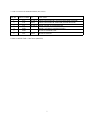
3.6 CN6 Connector for Paper Cutter
PIN NO. SIGNAL NAME
1
M+
2
M3
SW
4
GND
I/O
OUTPUT
OUTPUT
OUTPUT
-
FUNCTION
CUTTER MOTOR OPERATIONAL SIGNAL M+
CUTTER MOTOR OPERATIONAL SIGNAL MCUTTER SWITCH INPUT SIGNAL
GND
Using Connector : 5207-0410A (MOLEX)
Remarks : Use specified Paper Cutter. (Model name : AC-120/ACS-120)
9
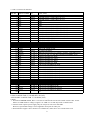
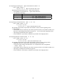
4. DIP SWITCH SETTING
DIP SWITCH
DS1-1
AUTO CUTTER
ON
OFF
FACTORY SETTING
ENABLE
DISABLE
OFF
2 CR SELECTION
LF ENABLE LF DISABLE
3 PRINT DENSITY
COMBINATION WITH J-6 (SEE BELOW)
OFF
4 DTR/XON-XOFF
XON-XOFF
OFF
DTR/DSR
5 INTERFACE
ON
OFF
6
"
SEE BELOW
OFF
7
"
OFF
8
"
OFF
JUMPER
SHORT
J1
OPEN
FONT SELECTION
J2
"
J3
"
FACTORY SETTING
SHORT CIRCUIT
SEE BELOW
SHORT CIRCUIT
SHORT CIRCUIT
J4
AUTO LOADING
ENABLE
DISABLE
SHORT CIRCUIT
J5
INPUT BUFFER
4K BYTES
72 BYTES
SHORT CIRCUIT
J6
PRINT DENSITY
COMBINATION WITH DS1-3
(SUPPLEMENTARY)
SEE BELOW
J7
BIT LENGTH
J8
PRINTER MECHANISM LT-282
DS18
OFF
OFF
OFF
OFF
OFF
OFF
OFF
OFF
ON
ON
ON
ON
ON
ON
ON
ON
7
OFF
OFF
OFF
OFF
ON
ON
ON
ON
OFF
OFF
OFF
OFF
ON
ON
ON
ON
6
OFF
OFF
ON
ON
OFF
OFF
ON
ON
OFF
OFF
ON
ON
OFF
OFF
ON
ON
8 BIT
5
OFF
ON
OFF
ON
OFF
ON
OFF
ON
OFF
ON
OFF
ON
OFF
ON
OFF
ON
SHORT CIRCUIT
SHORT CIRCUIT
7 BIT
SHORT CIRCUIT
LT-283
SHORT CIRCUIT
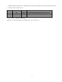
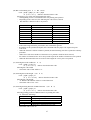
INPUT METHOD
PARALLEL INPUT
SERIAL INPUT
"
"
"
"
"
"
"
"
"
"
"
"
"
"
10
PARITY BAUD RATE
--NONE
1200 bps
"
2400 bps
"
4800 bps
"
9600 bps
"
19200 bps
ODD
1200 bps
"
2400 bps
"
4800 bps
"
9600 bps
"
19200 bps
EVEN
1200 bps
"
2400 bps
"
4800 bps
"
9600 bps
"
19200 bps
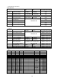
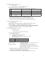
J3
2
1
INTERNATIONAL/JAPAN
INTERNATIONAL
CHARACTER
OPEN
OPEN
OPEN
JAPAN
JAPAN
OPEN
OPEN
SHORT
JAPAN
JAPAN
OPEN
SHORT
OPEN
INTERNATIONAL
SWEDEN
OPEN
SHORT
SHORT
INTERNATIONAL
DENMARK 1
SHORT OPEN
OPEN
INTERNATIONAL
U.K.
SHORT OPEN
SHORT
INTERNATIONAL
GERMANY
SHORT SHORT
OPEN
INTERNATIONAL
FRANCE
SHORT SHORT
SHORT
INTERNATIONAL
U.S.
DS1-
J3
6
PRINT DENSITY
OFF
OPEN
LIGHTER
OFF
SHORT
LIGHT
ON
OPEN
DARK
ON
SHORT
DARKER
11
5. POWER SUPPLY
5.1 SPECIFICATIONS
VCC : 5V ± 5% 145 mA
VP : 24V ± 5%
1.8A (Peak : approx.6A)
5.2 Precautions
(1) Design the product to supply power to VCC before VP When power is supplied to this control board.
(2) Design the product to turn off the power for VCC after VP when power is turned off.
(3) Make sure to turn off the power in case of connecting / disconnecting connectors.
(4) Make sure to use VCC and VP following their specifications.
(5) Make sure to use this control board connecting all of terminals between VP and P-GND.
6. Parallel interface
6.1 Specifications
Data input method
Control signals
: 8 bit parallel signal (DATA0 - 7)
: ACK, BUSY, STB, FAULT, PE, RESET
6.2 Explanation of input / output signals
DATA0-7
: 8 bit parallel signal (Positive logic)
STB
: Strobe signal to read 8 bit data (Positive signal)
RESET
: Signal to reset control board
ACK
BUSY
: 8 bit data request signal. Pulse signal output at the end of the BUSY signal
(Negative logic)
: Signal to indicate BUSY state of the printer.Input new data for "LOW" (Positive logic)
FAULT
PE
: Signal which is made "LOW" when printer is in alarm state.(Negative logic)
: Signal which is output when paper runs out.(Positive logic)
12
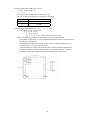
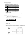
6.3 Electrical characteristics
(1) Input Signal Level
All the input signals are at TTL level.
"HIGH" level
: 2.0V MIN
"LOW" level
: 0.8V MAX
(2) Output Signal Level
All the input signals are at TTL level.
"HIGH" level
: 2.4V MIN
"LOW" level
: 0.4V MAX
(3) I/O Conditions
All the input signals are pulled up by 3.3KΩ.
<Printer side>
<Host side>
All the output signals are pulled up by 3.3KΩ.
13
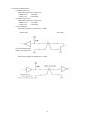
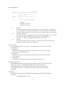
6.4 Timing chart
(1) Data Input and Printing Timing
ACK is not outputted.
T1, T2, T3 : 0.5 micro sec. MIN
T4
: 270 ns MAX
T5
: 2.3 micro sec. TYP
T6
: 500 ms MIN (On supplying power)
6.5 Data receiving control
When BUSY signal is "LOW", data from the host can be received. When it being "HIGH",
data can not be received.
6.6. Buffering
The size of buffer can be selected by setting of Jumper switch J5.
When 4K buffer is selected, as big data can be buffered in input buffer, host side can be released
immediately.
14
7. Serial interface
7.1 Specifications
(1) Data transfer system: Asynchronous
(2) Baud rates
1200, 2400, 4800, 9600, 19200 bps (Selectable by user)
(3) Configuration of one word
Start bit :
1 bit
Data bit :
7 bits or 8 bits (Selectable by user))
Parity bit :
Add/even or no parity (Selectable by user)
Stop bit :
1 bit or more
(4) Signal polarity
RS-232C
・ Mark
=
logic " 1" (-3V ∼ -12V)
・ Space
=
logic " 0" (+3V∼ +12V)
(5) Receiving data (RD signal)
RS-232C
・ Mark
=
1
・ Space
=
0
(6) Receiving control (DTR signal)
RS-232C
・ Mark
:
Data transfer not available
・ Space
:
Data transfer available
(7) Transmission control (TD signal)
DC1 code (11H) X-ON
:
Data reception available
DC3 code (13H) X-OFF :
Data reception not available
7.2 Explanation of Input / Output signals
7.2.1 Input / Output signals
(1) RD
Serial receiving data signal. On occurrence of framing error, overrun error, or parity error,
the data is printed as "?".
(2) DTR
When this signal is READY, write data or a command. When they are written in BUSY,
overrun error is occurred and data is ignored. Even during printing, data can be loaded in
the input buffer. Further, BUSY can take place on supply of power, during test printing,
during on-line, or on resetting.
(3) TD
When, while in data reception, the rest of input buffer on the printer side goes less than
10 bytes (72K bytes mode) or 128 bytes (4K bytes mode), DC3 (13H) data reception
impossible signals are output. When the rest of input buffer goes more than 20 bytes
(72 bytes mode) or 256 bytes(4K bytes mode), DC1 (11H) data reception possible signals
are output to the host. When DTR/DSR control having been selected in status
information transmission, it is first confirmed that DSR is "space" and data is sent.
When DTR/DSR control has not been selected, DSR is ignored and data is transmitted.
(4) FG
Case GND
(5) GND
Common GND on the circuit.
15
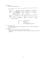
7.3 Date configuration
1 Start bit
2 Data bit (+ parity bit)
3 Stop bit ( 1 or more )
(1)
(2)
(3)
Start Bit
In 1/2 bit from the mark-to-space starting edge, state is read once again. When "space"
state is confirmed, it is recognized as the start bit. If it is "mark" state, it is not taken as
the start bit. Without taking it as an error, detection of a start bit is carried out once again.
Data Bit + Parity Bit
Data bit and parity bit are sampled at 1/2 start bit for time length equal to 1 bit. The state
thus sampled is taken as the data for the bit concerned. Bits are named as
Bit 0, Bit 1, ..... parity bit counted from the one close to the start bit.
Stop Bit
The stop bit is a mark level of 1 bit or more. With "space" having been detected on
detection of a stop bit, framing error takes place.
7.4 Error detection
Parity, framing, and overrun are detected. On detection of any error, the data are stored
in the buffer as "?".
(1) Framing Error
With "space" state having been detected on detection of a stop bit, error takes place.
The data are stored in the buffer as "?".
(2) Parity Error
With an error having been detected under specifying parity check, the data is stored
in the buffer as "?".
(3) Overrun Error
On detection of an overrun error, the data are stored in the buffer as "?".
7.5 Data receiving control
When DTR/DSR control having been selected, with BUSY signal at "LOW", data from the
host side are received. With the signal at "HIGH", they can not be received.
When DTR/DSR control not having been selected, after X-ON transmission, data is
received from the host side. No transmission of data can take place after X-OFF is
transmitted.
7.6 Buffering
Data transfer to the input buffer include DTR signals and TD signals as the control signals
concerned.
(1) DTR signals (See 7.2. (2).)
16
(2) TXD signals (See 7.2. (3).)
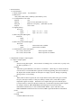
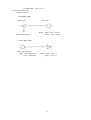
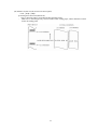
7.7 Electrical characteristics
(1) RS-232C Circuit
Input (RXD, DSR)
<Printer side>
<Host side>
RXD
MAX 232 Equivalent
Mark = (-8V) : stop bit
Space = (+8V) : start bit
Output (DTR, TXD)
MAX 232 equivalent
DTR (-8V) : When busy
(+8V) : when ready
TXD
Mark = (-8V) : 1
Space =(+8V) : 0
17
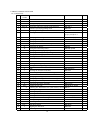
8. PRINT CONTROL FUNCTION
8.1 Command List
CONTROL
CODE
1
HT
2
CR
3
LF
4
ESC SP
5
!
6
%
7
&
FUNCTION
CODE
PAGE
Horizontal tab command
Print command
Printing and paper feed
Setting the right space amount of the character
Collective specifying printing mode
Specifying/canceling download character set
Defining download characters
09H
0DH
0DH
1BH 20H n
1BH21H n
1BH25Hn
1BH26H5nm
[ap1p2...p5xa]m-n+1
19
19
19
19
19
20
20
8
9
10
11
*
2
3
Specifying the bit image mode
Specifying/canceling underline
Specifying 1/6-inch line feed rate
Setting line feed rate of minimum pitch
1BH2Amn1n2[d]k
1BH2DH n
1BH32H
1BH33Hn
21
21
21
21
12
13
14
15
16
17
18
@
D
E
G
J
R
c3
Initializing the Printer
Setting horizontal tab position
Specifying/canceling highlighting
Specifying/canceling double printing
Printing and feeding paper n/203 inch
Selecting the international characters
NOP
1BH40H
1BH44H[n]k00H
1BH45Hn
1BH47Hn
1BH4An
1BH52Hn
1BH63H33Hn
21
22
22
22
22
23
23
19
20
21
22
23
24
25
26
27
28
29
30
31
32
33
34
35
36
37
38
39
40
41
c4
c5
d
p
t
v
u
{
V
$
¥
GS k
w
h
H
f
*
/
:
^
ESC =
a
i
NOP
Enabling/disabling the panel switches
Printing and feeding the paper by n lines
NOP
Selecting the character code table
Transmitting the printer status (Serial type)
NOP
Specifying/canceling the inverted characters
1BH63H34Hn
1BH63H35Hn
1BH64Hn
1BH70Hmn1n2
1BH74Hn
1BH75Hn
1BH76H
1BH7BHn
1BH56Hn
Specifying/canceling the 90 ° - right-turned
Specifying the absolute positions
1BH24Hn1n2
Specifying the relative positions
1BH5Cn1n2
Printing the bar code
1DH6BHn[“d”]k00H
Selecting the horizontal size (scale factor) of bar 1DH77n
Selecting the height of the bar code
1DH68Hn
Selecting of print position of HRI code
1DH48Hn
Selecting the font of HRI code
1DH66Hn
Defining the download bit image
1DH2An1n2[d]n1xn2x8
Printing the download bit image
1DH2FHm
Starting/ending macro definition
1DH3AH
Executing the macro
1DH5En1n2n3
Data input control
1BH3DHn
Aligning the characters
1BH61Hn
Activating auto cutter (Full cut)
1BH69H
18
23
23
23
24
24
24
25
25
26
26
26
27
27
27
27
28
28
29
29
29
30
30
30
42
m
Activating auto cutter (Partial cut)
1BH6DH
9.2 Command Details
(1) Horizontal Tab Command (HT)
Code : (09)h
Shifts the printing position to the next horizontal tab position. The horizontal tab position is set
by ESC D. Initial setting of the horizontal tab position is each 8 characters in 9th, 17th, 25th,
33rd, columns.
(2) Print Command (CR)
Code : (0D)h
1) When DS 1 -2 is OFF:
This command is ignored.
2) When DS 1- 2 is ON:
With data held inside the internal print buffer, printing and line feed are performed.
Without data inside the internal print buffer, however, no printing is performed.
(3) Printing and Paper Feed Command (LF)
Code : (0A)h
Prints data inside the input buffer and feeds lines based on the line feed amount having been set.
(4) Setting the right space amount of the characters (ESC SP n)
Code : (1B)h + (20)h + n
☆ {0 ≦ n ≦ 20} Data is described in Hex code.
The rightward space amount is set in dot unit (1/203 inch unit). In the initial value, it is n=0.
The rightward space amount in double wide mode is made double of the set volume.
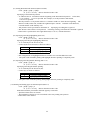
(5) Collective Specifying Printing Mode (ESC ! n)
Code: (1B)h + (21)h + n
☆ {0 ≦ n ≦ FF} Data is described in Hex code.
Printing mode is assigned. Each n bit indicates the following:
VALUE
BIT
FUNCTION
0
0
Character Font
Font A
1
Undefined
2
Undefined
3
High-lighting
Canceled
4
Double height
Canceled
5
Double width
Canceled
6
Undefined
7
Underline
Canceled
1
Font B
Specified
Specified
Specified
Specified
・With double height and double width being specified simultaneously, double wide and
double high characters are consisted.
・An underline is attached to the full character width, which, however, is not attached to the
part having been skipped by the horizontal tab. Neither is it attached to 90°-right-turned
characters.
・The underline width is as having been specified by <ESC - >. (The default setting is
1 dot width. )
In case that double wide character and normal character exist in same one line,
the layout of underline is consistent one.
19
31
(6) Specifying/Canceling Download Character Set (ESC % n)
Code: [1B]h + [25]h + [n]
☆ {0 ≦ n ≦ FF} data is described in Hex code.
Specifying/canceling download characters. Download characters and download bit images
cannot be defined simultaneously. Further, only the lowest bit (n0) is valid for n.
The lowest bit (n0) indicates the following.
n0
0
1
Function
Canceling download character
Specifying download character
(7) Defining Download Character (ESC & s n m a (D1D2 ∼Dn))
Code: [1B]h + [26]h + s +n +m +a +Dn
☆ {s = 03}
{20 (Hex) ≦ n ≦ 7E (Hex)}
{20 (Hex) ≦ m ≦ 7E (Hex)}
{0 ≦ a ≦ 0A (Hex)}
Defines the font of download characters of alphanumeric characters.
・ "s" indicates the number of bytes in vertical direction.
・ "n" indicates the start character code and m the end character code. To define only one character,
set n=m.
・ Character codes definable includes 95 ASCII codes in total between <20>H∼<7E>H.
・ "a" indicates the number of dots in horizontal direction for definition.
・ Dn is the data to be defined, which indicate a pattern equal to "a" dot in horizontal
direction from the left end. The rest of the pattern on the right side is filled with space.
The rest of data to be defined is s x a.
・ Download characters thus defined remain valid until redefinition, ESC @ execution,
GS * execution, or power OFF is practiced.
[EXAMPLE]
20
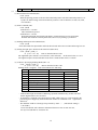
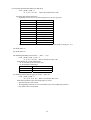
(8) Specifying the Bit Image Mode (ESC * m n1 n2 D1 ∼Dn)
Code : [1B]h + [2A]h + m + n1 + n2 + Dn
☆ {m= bit image mode (See the table below.)}
{0 ≦ n1 ≦ FF}
{0 ≦ n2 ≦ 02} Data is described in Hex code.
According to the number of dots specified in n1, n2, specify the bit image of mode n.
・The no. of dots printed is divided by 256, whose quotient is taken as n2 and residualas n1.
・The total no. of dots printed in the bit image is equal to n1 + (256 x n2).
・When bit image data have been input in excess of dot position of one line (448 dots) , the excess
data are discarded.
・d is bit image data, the bits subject to printing are taken as "1" and those not as "0".
・The bit image modes specified by m are shown as follows:
VERTICAL DIRECTION
HORIZONTAL DIRECTION
m(Hex)
MODE
NO. OF DOTS DOT DENSITY DOT DENSITY MAX. NO OF DOTS
0
8-dot signle density
8
67 DPI
101 DPI
224 (208)
1
8-dot double density
8
67 DPI
203 DPI
448 (416)
32
16-dot single density
24
203 DPI
101 DPI
224 (208)
33
16-dot double density
24
203 DPI
203 DPI
448 (416)
・ When the values set in m (bit image mode) are out of the above range, the data following after n1 is
processed as normal printing data.
・ After completion of bit image printing, printer returns to normal data processing mode.
* For maximum dots, the figure in ( ) is for LT- 283.
(9) Specifying/ Canceling Underline (ESC - n)
Code: [1B]h + [2D]h + n
☆ {0 ≦ n ≦ 02} data is described in Hex code.
Specifying/canceling an underline.
・An underline is attached to the full character width. It is, however, not attached to the part
having been skipped by horizontal tab command.
・An underline is not attached to a 90 °- right-turned characters.
・Types of underlines by n value are shown below:
n (Hex)
0
1
2
Type
Canceling an underline.
Specifying an underline for 1-dot width.
Specifying an underline for 2-dot width.
(10) Specifying 1/6 inch line feed rate (ESC 2)
Code : [1B]h + [32]h
The line feed rate per line is specified by 1/6 inch.
(11) Setting line feed rate of minimum pitch (ESC 3 n)
Code : [1B]h + [33]h + n
☆ {0 ≦ n ≦ FF} data is described in Hex code.
The line feed rate per line is specified by n/360 inch.
・The initial value is n = 60(1/6 inch)(18H), being 4.23 mm line feed rate.
(12) Initializing Printer (ESC @)
Code : [1B]h + [40]h
Clears data stored in the print buffer and brings various settings to the initial state (Default state).
・Data inside the internal input buffer are not cleared.
・Dip switches setting are read once again.
21
(13) Setting Horizontal Tab Position (ESC D n NUL)
Code : [1B]h + [44]h + n [00]h
☆ {0 ≦ n ≦ FF} Data is described in Hex code.
Specifying a horizontal tab position.
・"n" indicates the no. of columns from the beginning to the horizontal tab position. At this time,
n= set position− 1 is to be specified. For example, to set the position at 9th column,
n=8 is to be specified.
・The tab position is set at position where it is "character width x n" from the line beginning. The
character width, at this time, includes the rightward space amount. In double wide characters,
it is made double of the ordinary case.
・Tab positions can be specified are maximum 32. Specifying exceeding this is ignored.
・ESC D NUL clears all the set tab positions. Following clearing, horizontal tab command is ignored.
・Initial value is specified for each eight characters(9.17.25.33.) of ANK characters.
(14) Specifying/canceling highlighting (ESC E n)
Code : [1B]h + [45]h + n
☆ {0 ≦ n ≦ FF} Data is described in Hex code.
Specifying/canceling the highlighting characters.
・"n" is valid only for the lowest bit (n0).
・Control by the lowest bit (n0) is shown as follows:
n0
Type
0
Canceling highlighting.
1
Specifying highlighting.
・This is effective to all characters.
・Dot configuration of a highlighted character includes one extra dot added at its side.
・ The print result of Double printing and highlight character printing is completely same.
(15) Specifying/canceling Double Printing (ESC G n)
Code : [1B]h + [47]h + n
☆ {0 ≦ n ≦ FF} Data is described in Hex code.
Specifying/canceling the double printing.
・"n" is valid only for the lowest bit (n0).
・Control by n is shown as follows.
n0
Type
0
Canceling double printing.
1
Specifying double printing.
・The print result of Double printing and highlight character printing is completely same
.
(16) Printing and feeding paper at minimum pitch (ESC J n)
Code : [1B]h + [4A]h + n
☆ {0 ≦ n ≦ FF} Data is described in Hex code.
Prints data inside the print buffer and feeds paper by n/360 inch.
・Specified volume does not remain.
・The beginning of the line is to be considered as the next printing start position.
・Initial value is not defined.
22
(17) Selecting International Characters (ESC R n)
Code : [1B]h + [52]h + n
☆ {0 ≦ n ≦ 0A) Data is described in Hex code.
Selecting international characters.
・Depending on the value of n, following character sets are specified.
n(Hex)
CHARACTER SET
0
U.S.A.
1
France
2
Germany
3
U.K.
4
DenmarkⅠ
5
Sweden
6
Italy
7
Spain
8
Japan
9
Norway
A
DenmarkⅡ
・The initial value of n indicates the character set specified by Jumper setting (J1 - J3).
(18) NOP (ESC c3)
(19) NOP (ESC c5)
(20) Enabling/Disabling Panel Switch (ESC c 5 n)
Code : [1B]h + [63]h + [35]h + n
☆ {0 ≦ n ≦ FF} Data is described in Hex code.
Selecting the LF switch valid/invalid.
・ "n" is valid only in the lowest bit (n0).
・ "n" bit means the followings.
N0
Condition
0
LF SW valid.
1
LF SW invalid.
・ The initial value of n is "0".
(21) Printing and Feeding the paper by n lines (ESC d n)
Code : [1B]h + [64]h + n
☆* {0 ≦ n ≦ FF} Data is described in Hex code.
Prints data inside the buffer and feeds paper by n lines.
・Specified line does not remain.
・The beginning of the line is to be considered as the next printing start position.
・The initial value is not defined.
23
(22) Generating specified Pulse (ESC p m n1 n2)
Code : [1B]h + [70]h + m + n + n2
☆ {m = connector pin No. (See table below.)}
{0 ≦ n1 ≦ FF}
{0 ≦ n2 ≦ FF} Data is described in Hex code.
Signals specified by n1, n2 are output to Connector Pin m.
・Bit m (m0) means the followings.
m0
Condition
0
Drawer kick No. 2 pin
1
Drawer kick No. 5 pin
・ON time is considered as n1 x 2ms and OFF time as n2 x 2ms.
・When m is out of the defined range, n1, n2 are discarded, where no signals are output.
・Drive duty of Drawer is shown below:
ON time
≦ 0.2
ON time + OFF time
(Take OFF time as being 4 times or more longer than ON time.)
(23) Selecting Character Code Table (ESC t n)
Code : [1B]h + [74]h + n
☆ {0 ≦ n ≦ 1} Data is described in Hex code.
Selecting Page n on the character code table:
・ "n" means the followings.
n (Hex)
Condition
0
IBM Character #2
1
Japanese Character
・The initial value of n is specified by Jumper setting (J1 - J3).
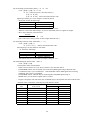
(24) Transmitting the printer status (ESC v)
Code : [1B]h + [76]h
Current printer status is transmitted..
・ Status sent out consists of 1 byte whose content is as in the table below.
・ In DTR/DSR control, after receptible state of the host (DSR signal being in SPACE state)
is confirmed, only 1 byte is transmitted. In XON/XOFF control, DSR signal state not being
confirmed, only 1 byte is transmitted.
・ In DTR/DSR control, when the host is in unreceptible state(DSR signal being in
MARK state), it waits until receptible state is created.
・ In paper end (paper near end) status, this command may be unreceptible state due to BUSY state.
Remarks. This command is valid only for serial interface model.
VALUE
BIT
0
1
2
3
4
5
6
7
FUNCTION
Not defined
Not defined
Paper end
Not defined
Not used
Not defined
Not defined
Not defined
24
0
1
With paper
Without paper
Fixed to 0
-
(25) Transmitting the status of Peripheral Equipment (ESC
Code : [1B]h + [75]h + n
☆ {n = 0}
Current status of connector pin No.3 is transmitted.
・ "n" means the followings.
n (Hex)
0
u
n)
Condition
Drawer Kick Connector No. 3
・Status transmitted consists of 1 byte whose content is as in the table below.
・Any equipment has not been connected to this connector, Bit 0 of n is always "1".
・In DTR/DSR control, after receptible state of the host (DSR signal being in SPACE state) is
confirmed, only 1 byte is transmitted. Further, in XON/ XOFF control, DSR signal state
not being confirmed, only 1 byte is transmitted.
・In DTR/DSR control, when the host is unreceptible state (DSR signal being in MARK state),
it keeps waiting until receptible state is created.
VALUE
BIT
FUNCTION
0
1
0
Not defined
1
Not defined
2
Paper end
Paper remains
Paper out
3
Not defined
4
Not used
Fixed to 0
5
Not defined
6
Not defined
7
Not defined
(Remarks) This command is valid only for serial interface mode.
(26) specifying/Canceling Inverted Characters (ESC { )
Code : [1B]h + [7B]h + n
☆ {0 ≦ n ≦ FF} Data is described in Hex code.
Specifying/canceling inverted characters.
・ "n" is valid only for the lowest bit (n0).
・ Bit n (n0) means the followings.
n0
0
1
Condition
Canceling inverted characters.
Specifying inverted characters.
・Inverted printing means printing the line at 180°turned.
・This is valid only when this is specified at the beginning of a line.
・The initial value of n is "0".
25
(27) Specifying/Canceling 90°-right- turned Characters (ESC V n)
Code : [1B]h + [56]h + n
☆{0 ≦ n ≦ 1} Data is described in Hex code.
Specifying/canceling characters 90°-right- turned character.
・ No underlines are attached to 90°-right- turned characters .
・ "n" means the followings.
n (Hex)
0
1
Condition
Canceling 90°-right- turned Characters
Specifying 90°-right- turned Characters
・The initial value of n is "0".
(28) Specifying Absolute Positions (ESC $ n1 n2)
Code : [1B]h + [24]h + n1 + n2
☆ {0 ≦ n1 ≦ FF}
{0 ≦ n2 ≦ 1} Data is described in Hex code.
The printing start position is specified in the number of dots from the beginning of line.
(1/20 inch unit)
・ The number of dots is divided by 256, whose quotient is taken as n2 and the residual as n1.
Therefore, the printing start position is equal to n1 + n2 x 256 from the beginning of line..
・ Specifying beyond the line end is ignored.
・ In case underline is specified, no underline is provided to the skipped portion.
(29) Specifying Relative Positions (ESC ¥ n1 n2)
Code : [1B]h + [5C]h + n1 + n2
☆ {0 ≦ n1 ≦ FF}
{0 ≦ n2 ≦ FF} Data is described in Hex code.
The printing start position is specified in the number of dots from the current position.
・ Rightward direction is taken as plus and leftward direction as minus.
・ To specify N dot in minus (left) direction, use a complement of N for assignment.
− N dots = 65536 − N
・ The number of dots is divided by 256, whose quotient is taken as n2 and the residual as n1.
・ Specifying exceeding the end of line is ignored.
・ In case underline is specified, no underline is provided to the skipped portion.
26
(30) Bar Code Printing (GS k n Dn NUL)
Code : [1D]h + [6B]h + n + Dn + [00]h
☆ {0 ≦ n ≦ 7} Data are described in Hex code.
Specifying a type of bar code and printing bar codes.
・ The beginning of line is considered as the next printing start position.
・ Depending on the value of n, the following bar code can be selected.
・ Dn indicates a character code to be printed.
n (Hex)
0
1
2
3
4
5
6
7
・
・
・
・
・
Bar Code System
UPC-A
UPC-E
JAN13 (EAN)
JAN 8 (EAN)
CODE 39
ITF
CODABAR (NW-7)
CODE 128
Maximum Columns
--------15 (14) *
26 (24) *
19 (18) *
17 (15) *
* The figure in ( ) is for LT-283.
When data being held in the print buffer, this command is ignored.
Regardless of the specified feed pitch, this command feeds the paper to be required to print
a bar code.
When the character code Dn cannot be printed, the data following after this is printed as ordinary
print data.
When a bar code whose number of characters to be printed is fixed has been selected,
the number of characters have to be always made equal to the number of characters to be printed.
When the horizontal direction exceeds one line length, the excess part is not printed.
(31) Selecting Bar Code width (GS w n)
Code : [1d]H + [77]H + N
☆ {2 ≦ n ≦ 4} Data is described in Hex code.
Selecting bar code width.
・ The initial value of this width is "3".
(32) Selecting Bar Code Height (GS h n)
Code : [1d]H + [68]H + N
☆ {1 ≦ n ≦ FF} Data is described in Hex code.
Selecting bar code height.
・ "n" indicates the number of dots in vertical direction.
・ The initial value of n is "162".
(33) Selecting Printing Position of HRI Characters (GS H n)
Code : [1d]H + [48]H + N
☆ {0 ≦ n ≦ 3} Data is described in Hex code.
Selecting printing position of HRI characters in printing bar codes.
・ "n" means the followings.
n (Hex)
Printing Position
0
No printing
1
Above the bar code
2
Below the bar code
3
Both above and below the bar code
・ The initial value of n is "0".
27
(34) Selecting the font of HRI code (GS f n)
Code : [1D]h + [66]h + N
☆ n = 0, 1
Selecting the font of HRI code in printing bar code.
The type of font can be printed by selecting n is as follows.
n
0
1
Font
Font A
Font B
(35) Defining Download Bit Image (GS * n1 n2 Dn)
Code : [1D]h + [2A]h + n1 + n2 Dn
☆ {1 ≦ n1 ≦ FF}
{1 ≦ n2 ≦ 48}
{n1 × n2 ≦ 1311} Data is described in Hex code.
Defines downloading bit images of the number of dots specified by n1/n2.
・ The numbers of dots are n1 x 8 in horizontal direction and n2 x 8 in vertical direction.
・ Dn indicates bit image data.
・ The download bit image thus defined remains effective until redefinition, ESC @
execution, ESC &, or power OFF takes place.
・ A download character and a download bit image cannot be defined simultaneously.
With this command executed, defined content of a download character is cleared.
・ Relations between the bit image data and the dot defined are shown below:
28
(36) Printing Download Bit Image (GS / m)
Code : [1D]h + [2F]h + m
☆ {0 ≦ m ≦ 3} Data is described in Hex code.
Prints download bit iamges in a mode specified by m.
・ Modes can be selected by m are shown ilable for selection with m are shown below.
・
・
・
・
m
MODE NAME
0
1
2
3
Normal mode
Double wide mode
double high mode
Double wide/double high
mode
DOT DENSITY IN
VERTICAL DIRECTION
203 DPI
203 DPI
101 DPI
101 DPI
DOT DENSITY IN
HORIZONTAL DIRECTION
203 DPI
101 DPI
203 DPI
101 DPI
When data exist inside the print buffer, this command is ignored.
When a download bit image has not been defined, this command is ignored.
A portion of a download bit image exceeding one line length is not printed.
A download character and a download bit image cannot be defined simultaneously.
(37) Starting / Ending Macro Definition (GS :)
Code : [1D]h + [3A]h
Specifying starting / ending macro definition. Maximum content available for macro
definition is 2048 bytes. A portion exceeding 2048 bytes is not defined.
・ Even with ESC @ (initialization of the printer) having been executed, defined content is not
cleared. Therefore, it is possible to include ESC @ into the content of macro definition.
・ Normal printing operation is carried out even while in macro definition
(38) Macro Execution (GS^n1 n2 n3)
Code : [1D]h + [5E]h + n1 + n2 + n3
☆ {0 ≦ n1 ≦ FF}
{0 ≦ n2 ≦ FF}
{0 ≦ 3 ≦ 1} Data is described in Hex code.
Executing contents defined in macro.
・ "n1∼n3" indicate as follows:
n1 : The number of times of macro execution
n2 : Waiting time on macro execution
Waiting time of n2 x 100 msec is given for every execution.
n3 : Macro execution mode
n3
0
1
Mode
Continuous execution
Execution by LF SW
Continuous execution
: The Macro is executed n1 times continuously at the time
intervals specified by n2.
Execution by FEED SW
: After waiting for lapse of time specified by n2,
the ERROR LED flickers and the LF switch is waited
to be pressed. When it is pressed, the macro is executed once.
This action is repeated n1 times.
・ When this command is received while in macro definition, suspension of macro definition
is indicated. At this time, the defined content is cleared.
・ No execution takes place when macro is held undefined or n1=0.
・ While in macro execution with n3=1, paper feed with the LF SW is not available.
29
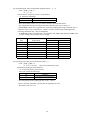
(39) Data Input Control (ESC = n)
Code : [1B]h + [3D]h + n
☆ {0 ≦ n ≦FF} Data is described in Hex code.
Selecting equipments in which data input from the host is effective.
・ Each bit of n indicates as follows:
VALUE
BIT
EQUIPMENT
0
1
0
Printer
Invalid
Valid
1
Not defined
2
Not defined
3
Not defined
4
Not defined
5
Not defined
6
Not defined
7
Not defined
・ When the printer has not been selected, this printer abandons all the received data until it
is selected by this command.
・ Even when the printer has not been selected, it can become BUSY state through printer
operation.
・ The initial value of n is "1".
(40) Aligning the characters (ESC a n)
Code : [1b}h + [61]h + n
☆ {0 ≦ n ≦ 2} Data is described in Hex code.
All the printed data within one line are aligned in the specified position.
・ Depending on n value, positional alignment is carried out as in the table below:
n (Hex)
POSITION
0
Left end alignment
1
Centering
2
Right end alignment
・ This is valid only when n is inputted at the beginning of line.
・ The initial value of n is "0".
(41) Full Cut (ESC i) (In selection of cutter option)
Code : [1B]h + [69]h
Activating auto cutter unit (Full cut)
・ This is valid only when n is inputted at the beginning of line.
・ Make sure to feed the paper by 18 mm or more before cutting paper, unless characters remain
before the cutting point.
30
(42) Partial Cut (ESC m) (In selection of cutter option)
Code : [1B]h + [6D]h
Activating auto cutter unit (Partial cut)
・ This is valid only when n is inputted at the beginning of line.
・ Make sure to feed the paper by 18 mm or more before cutting paper, unless characters remain
before the cutting point.
31
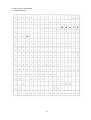
9. CHARACTER CODE TABLE
9.1 INTERNATIONAL
32
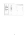
9.2 INTERNATIONAL CHARACTER CODE TABLE
33
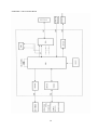
APPENDIX 1. BLOCK DIAGRAM
34
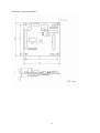
APPENDIX 2. BASIC DRAWING
35