1
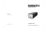
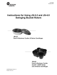
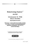
Se
Sequi
qu -G
en en®
ci G
ng T
Ce
ll
Sequi-Gen® GT
Nucleic Acid
Electrophoresis Cell
Instruction Manual
Catalog Numbers
165-3860, 165-3861,
165-3862 and 165-3863
For Technical Service Call Your Local Bio-Rad Office or in the U.S. Call 1-800-4BIORAD (1-800-424-6723)
Note
To insure best performance from the Sequi-Gen GT electrophoresis system, become fully acquainted with these operating instructions before using the cell. Bio-Rad recommends that you first read these
instructions carefully. Then assemble and disassemble the cell completely without casting a gel. After
these preliminary steps, you should be ready to cast and run a gel.
Bio-Rad also recommends that all Sequi-Gen GT components and accessories be inspected for damage, cleaned as recommended in this manual, and rinsed thoroughly with distilled water before use.
Record the following for you records:
Model
Catalog No.
Date of Delivery
Warranty Period
Serial No.
Invoice No.
Purchase Order No.
Warranty
Bio-Rad Laboratories warrants the Sequi-Gen GT electrophoresis system against defects in
materials and workmanship for 1 year. If any defects occur in the instrument during this warranty period, Bio-Rad Laboratories will repair or replace the defective parts free. The following defects, however, are specifically excluded:
1. Defects caused by improper operation
2. Repair or modification done by anyone other than Bio-Rad Laboratories or an authorized
agent.
3. Use of fittings or other spare parts supplied by anyone other than Bio-Rad Laboratories.
4. Damage caused by accident or misuse.
5. Damage caused by disaster
6. Corrosion due to use of improper solvent or sample
This warrant does not apply to parts listed below:
1. Platinum wire
2. Glass plates
For any inquiry or request for repair service, contact Bio-Rad Laboratories after confirming the model
and serial number of your instrument.
Table of Contents
Page
Warranty Information ........................................................................Inside Front Cover
Section 1
General Information....................................................................................1
1.1
1.2
Introduction to Sequi-Gen GT DNA Electrophoresis Cell .......................................1
Specifications .............................................................................................................5
Section 2
Description of Major Parts .........................................................................6
2.1
2.2
2.3
Sequi-Gen GT Parts ...................................................................................................6
Gel Reagents and Electrophoresis Buffers ................................................................7
Electrical Path.............................................................................................................8
Section 3
Cleaning and Maintenance .........................................................................8
3.1
3.2
Cleaning and Siliconizing Plates................................................................................8
Cleaning Plastic Parts.................................................................................................9
Section 4
Operating Instruction................................................................................10
4.1
4.2
4.3
4.4
4.5
4.6
4.7
Before Assembly ......................................................................................................10
Assembling the Glass Plate Sandwich.....................................................................10
Casting the Gel .........................................................................................................12
Preparing for Operations ..........................................................................................17
Loading the Gel........................................................................................................18
Gel Electrophoresis ..................................................................................................19
Disassembly..............................................................................................................20
Section 5
Troubleshooting Guide ..............................................................................22
5.1
5.2
Operational Troubleshooter .....................................................................................22
DNA Sequencing Artifacts ......................................................................................23
Section 6
Equipment and Accessories ......................................................................26
6.1
6.2
6.3
6.4
6.5
Sequi-Gen GT Nucleic Acid Electrophoresis Cells and Accessories .....................26
Electrophoresis Reagents .........................................................................................30
Power Supplies and Slab Gel Dryers.......................................................................31
DNA Template Purification, Sequencing, and Cloning Products...........................31
Liquid Handling .......................................................................................................32
Section 7
Appendix A- Applications .........................................................................32
7.1
7.2
7.3
7.4
7.5
DNA Sequencing Checklist .....................................................................................32
Standard Gel Protocol ..............................................................................................33
Gel Drying Autoradiography ...................................................................................34
Applications for Sequi-Gen GT Nucleic Acid Electrophoresis Cell ......................34
Suggested Reading ...................................................................................................35
Section 1
General Information
1.1 Introduction to the Sequi-Gen* GT Nucleic Acid Sequencing Cell
The Sequi-Gen GT cell is a modular electrophoresis cell capable of separating nucleic
acids with single base-pair resolution, using a vertical slab gel format. This manual tells you
how to operate and care for your new Sequi-Gen GT cell. Read Sections 1 through 3 before
attempting to assemble the cell. The remainder of the manual gives you detailed procedures,
a troubleshooting guide, and parts lists.
The Sequi-Gen GT cell employs a simple design that provides maximum resolution with
high reproducibility, while eliminating the temperature artifacts which often occur in sequencing gels. Some of the unique features of this sequencing cell are the gel casting method,
durable construction, modular components, and ease of operation, which make this the most
advanced DNA sequencing cell available.
Note:
This manual contains instructions for the Sequi-Gen GT electrophoresis systems only.
Prior to the release of the Sequi-Gen GT systems, Bio-Rad supplied two similar sequencing electrophoresis cell systems: the original Sequi-Gen cell and the Sequi-Gen II cell. This
manual does not provide information on these systems. Contact your Bio-Rad representatives for information on the original Sequi-Gen and the Sequi-Gen II systems.
* US Patent number 4,663,015 issued to Bio-Rad Laboratories.
Safety
The Sequi-Gen GT cell has safety features to protect the operator from injury. These
features include:
•
Interlocking safety lids to prevent high voltage buffer shock
•
Permanently sealed upper buffer chamber to prevent leaks and arcing
•
Plastic components made from self-extinguishing material
•
Full-length clamps to shield user from edges of glass plates
•
Chemically tempered glass plates that significantly reduce glass plate breaking due to
overheating and routine heating and cooling
•
No exposed metallic parts
•
Pour spout in lower buffer chamber allows radioactive buffer to be easily and safely
poured for disposal
Important:
This apparatus meets I.E.C. 1010-1† safety standards. Sequi-Gen GT systems are safe to
use when operated in accordance with the instructions. This instrument should not be
modified in any way. Alteration of this instrument will:
•
Void the manufacturer’s warranty
•
Void the IEC1010-1 safety certification
•
Create a potential safety hazard
† IEC1010-1 is an internationally accepted electrical safety standard for laboratory instruments.
1
Bio-Rad is not responsible for any injury or damage caused by the use of this instrument
for purposes other than those for which it is intended, or by modifications to the instrument
not performed by Bio-Rad or an authorized agent.
Power to the Sequi-Gen GT cell is supplied by an external DC power supply. This power
supply must be ground isolated in such a way that the DC voltage output floats with respect
to ground. The recommended power supply for this apparatus is the PowerPac 3000 power
supply. The maximum specified operating parameters for the Sequi-Gen GT cell are:
Maximum operating voltage – 3,000 VDC
Maximum operating power – 100 Watts
Electrical current to the Sequi-Gen GT cell enters the unit through the top and bottom
safety covers, providing a safety interlock to the user. Current flow to the cell is broken when
either safety cover is removed. Do not attempt to circumvent this safety interlock. Always
turn the power supply off while working with the sequencing cell when the safety covers are
not connected.
No user-serviceable parts are contained in this apparatus. To insure electrical safety, do
not attempt to service this apparatus.
Caution — Arcing
Arcing within an electrophoresis cell is represented by sparks, smoke, or charred surfaces
created when an electrical short has developed. Arcing can occur if the buffer level drops
below the recommended height, if there is buffer leakage, or if loose electrical connections
exists. If arcing is detected during electrophoresis, immediately remove the source of
electrical current (i.e., turn off the power supply).
Always use a power supply that is capable of detecting electrical conditions that may
cause accidental electrical shock or damage to the apparatus. The PowerPac 3000 power
supply contains safety features such as arc, no load, overload, rapid change in resistance, and
ground leak detection capabilities, that will reduce the chance of accidental electrical shock
and damage to the electrophoresis cell.
Before every use, inspect all plastic parts, glass plates, all electrical cables, jacks, and
receptors for loose connections, cracks, charring, or corrosion. Do not use any part that is
cracked, chipped, charred, or corroded. These parts may cause arcing. Contact your Bio-Rad
representative before using a part that may cause buffer leaking or arcing.
Warning:
Never allow the gel to exceed 60 ˚C. Excessive heat may crack the plates or cause the
silicon bond of the IPC to deteriorate.
Make sure that the upper and lower buffer chambers are filled with buffer during
electrophoresis. Do not allow the buffer level to drop below the level of the short glass plate
of the upper buffer chamber or below the bottom of the IPC assembly in the lower buffer
chamber at any time.
Certain solvents and cleaning agents should be avoided with this unit. Refer to Section 3.2
for compatible solvents, reagents and cleaning agents.
Definition of Symbols
Caution, risk of electrical shock
Caution (refer to accompanying documents)
2
System Components
Each Sequi-Gen GT system comes with the components listed in Table 1.1. Check your
unit to be sure all items are present. Note any damage to the unit which may have occurred
during shipping. Notify Bio-Rad Laboratories if any items are missing or damaged.
Table 1.1. Sequi-Gen GT System Components
Item
GT Universal Base
Stabilizer Bar
GT Safety Covers1
GT IPC, with bonded inner (short) glass plate2
Outer (long) Glass Plate2
GT Clamp Set (left and right clamp)3
Precision Caster Base1
Precision Caster Gasket 1
Precision Caster Syringe 4
Precision Caster Tubing, 60 cm
Precision Caster Luer Tapers
IPC Drain Port/Tubing Connector
Gel Temperature Indicator
Vinyl Spacers, 0.4 mm thick3
Vinyl Sharkstooth Comb, 0.4 mm thick5
Leveling Bubble
Instruction Manual
Quantity
1
1
1
1
1
1
1
1
1
1
4
1
1
2
1
1
1
1 Parts come in 21 cm or 38 cm widths
2 GT IPC and Glass Plates are 21 x 40, 21 x 50, 38 x 30 cm or 38 x 50 cm sizes
3 GT Clamp Sets and Vinyl Spacers are either 30 cm, 40 cm or 50 cm lengths
4 Syringe sizes are 60 cc for 21 cm systems and 140 cc for 38 cm systems
5 Vinyl Sharkstooth combs are 24 well (25 teeth) for 21 cm units or 49 well (50 teeth) for 38 cm units
See Section 6 for information on accessories and replacement parts.
General Description
The Sequi-Gen GT DNA sequencing cell uses several innovative design features that are
especially useful for DNA/RNA sequencing or other nucleic acid separation applications.
Sequi-Gen GT DNA sequencing cell features and benefits include:
Features
Benefits
Unique, horizontal, syringe injected gel
casting method
Easy gel casting without tape, grease, and
acrylamide spills and waste
Upper buffer chamber heat
distribution system
Provides uniform gel temperature that
prevents smiling
Permanently sealed upper buffer
chamber
No gaskets or grease needed to provide leakfree electrophoresis
(continued on the next page)
3
Features
Benefits
A universal base accepts all gel dimensions,
including wide and narrow gel formats of
various lengths
Modular system allows different sized
gels to be used with the same lower buffer
chamber
Injection molded parts
Provides years of rigorous use
Chemically tempered glass plates
Resists cracking due to overheating
and rough handling
One-piece, lever-operated clamps
Conveniently and easily slides onto gel
sandwich, and shields edges of glass plates
from operator contact
Molded chambers with pour spouts or
drain ports
Easy and safe radioactive buffer disposal
Machined vinyl spacers and
sharkstooth combs
Uniform thickness of combs and spacers
reduces well-to-well leakage during
sample loading
Sequi-Gen GT Buffer Heat Dissipation
Uneven dissipation of the Joule heat produced by the gel during electrophoresis causes
electrophoresis artifacts. “Smiling” is a common artifact that develops when a gel sandwich
loses heat more efficiently at the edges than in the center. When a gel runs hotter in the
center, the electrical resistance decreases, and more current flows down the center. As the
current flow increases, the gel heats even more. Thus a positive feedback loop is set up which
results in the lanes near the center of the gel running hotter, and therefore faster, than the
lanes near the edges. Smiling can lead to ambiguity in reading the sequence.
The Sequi-Gen GT cell employs natural convection and conduction of the upper buffer
to distribute heat evenly. The problems of uneven heat dissipation are avoided. Complicated,
expensive thermostatic plates are not necessary.
A thin, transparent, upper buffer chamber, called an IPC (Integral Plate Chamber), acts as
a heat sink across the full area of the gel. Convection occurs any time a slight temperature
gradient develops, mixing the buffer (and heat) to prevent smile patterns from developing.
Convection is the most effective way to distribute heat evenly. The upper buffer dampens
temperature fluctuations in the gel, and adds to the reproducibility of each run. The contact
between the buffer and the gel plate is direct and uniform. Thermal and physical stresses are
reduced. The sample loading wells are always at the same temperature as the gel, resulting in
fewer re-annealing problems. Bubbles of gas, generated by electrolysis along the cathode,
rise through the buffer. These bubbles also help to prevent temperature gradients from
forming by stirring the upper buffer while rising to the top of the IPC chamber.
Sequi-Gen GT Gel Casting
Because of their large size, casting sequencing gels has traditionally been extremely
problematic. Taping the bottom or sides of the glass plate sandwich is time consuming and
does not always result in a perfect seal. Thus, vacuum grease is required to seal corners and
edges. The user must then “wrestle” with the gel mold in order to pour the gel correctly.
Sliding glass plates, or plate dropping methods always result in acrylamide spills and waste.
Cleaning the hazardous neurotoxin after the spills is also time consuming.
4
The precision caster allows quick and easy gel casting without acrylamide spills or waste.
By casting the gel with a syringe through the precision caster base, gels can be poured in less
than 1 minute. The gel is cast with the glass plate assembly in the horizontal position. Two
full-length clamps secure the assembly and allow attachment of the precision caster base to
the bottom of the glass plate sandwich. A seal between the caster gasket and the plates is
created without tape or grease. The gel is injected from the bottom of the glass plate sandwich
(via the injection port of the precision caster base) and moves to the top of the glass plates as
a dome-shaped gel front. Acrylamide spills and waste can be eliminated by controlling the flow
of the gel front at the top of the glass plates.
Modular Assembly
There are four IPC dimensions to choose from, as shown in Figure 1.1. One universal
base functions as the lower buffer chamber for all IPC sizes.
21 x 40 cm 21 x 50 cm
38 x 30 cm
38 x 50 cm
Fig. 1.1. Interchangeable sizes.
1.2 Specifications
General Specifications
Base footprint
16 x 48 cm
Maximum unit height
65 cm (50 cm cells); 55 cm (40 cm cells); 45 cm (30 cm cells)
IPC sizes
21 x 40, 21 x 50, 38 x 30 cm and 38 x 50 cm
(width x length)
Actual gel sizes
17 x 40, 17 x 50, 34 x 30 cm, 34 x 50 cm
Gel thickness range
0.25 – 0.75 mm
Nominal gel volumes (0.25 mm) 17 ml (21 x 40 cm); 21 ml (21 x 50 cm); 40 ml (38 x 30 cm);
43 ml (38 x 50 cm)
Nominal gel volumes (0.40 mm) 27 ml (21 x 40 cm); 34 ml (21 x 50 cm); 50 ml (38 x 30 cm);
68 ml (38 x 50 cm)
Minimum upper buffer volumes
500 ml (21 x 40 cm); 575 ml (21 x 50 cm); 650 ml
(38 x 30 cm); 1,400 ml (38 x 50 cm)
Minimum lower buffer volume
350 ml
Maximum lower buffer volume 500 ml
Electrical Specifications
Electrical Safety Certification
IEC 1010-1
Rated voltage limit
3,000 volts
Rated power limit
100 watts
Rated temperature limit
60 ˚C
Electrical cables
Rated to 3,000 volts (VDC)
Electrical leads
Rated to 3,000 volts (VDC)
Banana plugs
Rated to 3,000 volts (VDC)
5
Construction Specifications
GT IPC panel
Injected molded polycarbonate
GT safety covers
Injected molded polycarbonate
Universal base
Injected molded polycarbonate
Stabilizer bar
Injected molded polycarbonate
GT clamp set
PVC clamp body
Protruded G10 polyester/glass cam shaft
Polycarbonate insulated stainless steel rod
Glass plates
Chemically tempered 4.8 mm float glass
Combs and spacers
Plastic or machined vinyl (see Sections 2.7 and 6.1)
Electrodes (IPC and base)
Platinum, 0.25 mm diameter
Banana plugs (IPC and base)
Gold plated stainless steel, 5.08 cm length
Electrical cables
Dual, 20 AWG, tinned copper wire cable
Flame retardant polyurethane insulation jacket
Electrical leads
Polyurethane insulated nickel silver, 2.95 cm length
Precision caster base
Injection Molded Polycarbonate
Tubing
Polyurethane, 3.2 mm internal diameter,
4.8 mm outer diameter
Luer taper
Polypropylene, 3.2 mm internal diameter
Gasket
Silicon Foam Sponge
Syringe
Polypropylene, 60 cc or 140 cc
Drain port connector
Polypropylene (quick coupling assembly)
3.2 mm internal flow diameter
Section 2
Description of Major Parts
2.1 Sequi-Gen GT Parts
See Figures 2.1 and 2.2 for Sequi-Gen GT part identification.
Sharkstooth Comb
Precision Caster Base
Drain Port
Syringe
Leveling Bubble
Syringe
Tubing
GT Lever Clamps
Luer Taper
Precision Caster Base Injection Port
Fig. 2.1. Sequi-Gen GT gel casting parts.
6
Precision Caster Cam Peg
GT Lever
Clamp
GT Top
Safety
Cover
IPC
(Integral
Plate
Chamber)
GT Lever
Clamp
Stabilizer
Bar
GT Bottom
Safety Cover
Se
Sequi
qu -G
en en®
ci G
ng T
Ce
l
l
GT Base
Leveling Feet
Fig. 2.2. Sequi-Gen GT nucleic acid electrophoresis cell.
2.2 Gel Reagents and Electrophoresis Buffers
For most DNA sequencing or nucleic acid separations, a 19:1 acrylamide:bis solution is
required. A 1x TBE (Tris, boric acid and EDTA) solution is the preferred electrophoresis
buffer. Reproducibility is affected by the quality of the gel and buffer reagents. A full line of
high quality polyacrylamide gel reagents and nucleic acid electrophoresis buffers is available
from Bio-Rad. Premixed reagents and buffers are also available and offer convenience, time
savings, and reproducible results. Each reagent and buffer is purified to meet rigorous quality
control standards. See Section 6.2 for ordering information.
7
2.3 Electrical Path
Both electrode wires are positioned near the bottom of the gel. The upper buffer carries the
current from the cathode up to the top of the plates near the fill spout, where the gel is exposed.
The lower buffer contacts the gel at the bottom edge of the plates in the standard fashion
(See Figure 2.3).
Fill spout
Upper buffer
Polycarbonate
panel
Bonded glass
plate
Gel
Outer glass
plate
IPC
drain port
Silicone
adhesive bond
Lower
buffer
Fig. 2.3. Electrical path through IPC (Integral Plate Chamber) to lower buffer reservoir.
Section 3
Cleaning and Maintenance
3.1 Cleaning and Siliconizing Plates
Important:
To insure “bubble-free” gels using the Sequi-Gen GT precision caster, the glass plates
must be thoroughly cleaned and the outer (long) glass plate siliconized or coated before
each use.
1. Clean both Sequi-Gen GT glass plates (IPC and outer plates) thoroughly before each use.
• Carefully place the plate into the sink and rinse with warm water.
• Pour powdered lab detergent (Alconox [Alconox, Inc.] or Micro [International
Products]) into a gloved hand and add sufficient water to make a paste.
• Apply the paste and scrub the entire glass surface with a gloved hand, using circular
motions.
8
• Rinse off all of the detergent with warm water.
• Rinse with deionized water.
• Wipe the cleaned plate with a large lint free tissue to dry.
2. Inspect the plates carefully for pieces of detergent, dried polyacrylamide, or other particles.
Rewash if necessary.
3. Perform siliconizing under a fume hood, to reduce the hazard from breathing silanizing
reagent. Alternatively, several non-toxic, non-corrosive glass plate coating solutions are
commercially available. We recommend siliconizing or coating only the outer (long)
plate, so that when the plates are separated, the gel sticks to the IPC-bound glass plate.
• Use a glass Pasteur pipette to dispense 2 ml of the silanizing reagent onto the front
plate. Coat the plate completely and evenly by spreading the silanizing reagent on the
plate surface with a large lint free tissue, using a motion that travels from the top to the
bottom of the plate.
Caution: Do not siliconize the IPC plate unless hexane, heptane, or water is used as a
solvent in the silanizing reagent. Other organic solvents will craze or damage the IPC
plastic and weaken the adhesive bond.
• Never heat an IPC in an oven. Severe damage will result to the adhesive bond. Use
siliconizing compounds that react, or cure, at room temperature.
Note: If the gels will be fixed or stained, the IPC (short) plate should be siliconized or
coated, since its immersion into fixing or staining solutions is not recommended.
4. Prior to assembling the plates, apply a small amount of ethanol to each plate and rub to
dryness with a tissue. Using the same tissue, clean the spacers.
3.2 Cleaning Sequi-Gen GT Components
1. Rinse the universal base buffer chamber, stabilizer bar, combs, spacers and precision
caster base, gasket, syringe and tubing assembly with a mild detergent solution in warm
water. Use a soft-bristled brush or sponge to remove polyacrylamide gel pieces.
Note: Do not snag or break the electrode wire in the universal base while cleaning.
2. Rinse thoroughly with warm water and air dry.
Compatible Cleaning Agents for Polycarbonate Parts
Chemically compatible cleaners must be used to ensure long life of parts. These include:
• Aqueous solutions of soaps and mild detergents
• Organic solvents:
• Hexane
• Aliphatic hydrocarbons
• Alcohols
• Methanol
• Ethanol
• Isopropyl alcohol
• Dilute acids
9
Caution: Do not touch plastic molded parts with solvents that contain chlorinated
hydrocarbons or aromatic hydrocarbons (e.g., carbon tetrachloride, toluene, methyl ethyl
ketone, acetone).
Do not use abrasive or highly alkaline cleaners on the polycarbonate plastic IPC panel.
(The glass may be cleaned with abrasive or strong alkaline detergents, if adequate care is
taken to avoid contact with the plastic panel.)
Do not soak plastic parts in detergents more than 30 minutes.
Cleaning the Clamps
Rinse the clamps with warm water, and wipe any polymerized acrylamide off the clamping
surfaces. Drain the banana plug mounts at the top of the clamps, and wipe the clamping
surfaces dry before each use. Do not use organic solvents to clean the clamps.
Section 4
Operating Instructions
4.1 Before Assembly
1. Thoroughly clean all parts as described in Section 3.
Caution: Certain solvents and cleaning agents should be avoided. Refer to Section 3.2 for
compatible cleaning agents.
2. Depending on the size of the Sequi-Gen GT IPC, make up the appropriate amount of
electrode buffer (typically 1x TBE) from Table 4.1.
Table 4.1. Electrode Buffer Volumes
IPC Size
Total Buffer Required
21 x 40 cm
21 x 50 cm
38 x 30 cm
38 x 50 cm
850 ml
925 ml
1,000 ml
1,750 ml
Upper
Lower
500 ml
575 ml
650 ml
1,400 ml
350 ml
350 ml
350 ml
350 ml
4.2 Assembling the Glass Plate Sandwich
After the Sequi-Gen GT components have been washed and the glass plates siliconized
or coated, assemble the Sequi-Gen GT apparatus. Always wear gloves while handling the
glass plates during assembly to avoid fingerprints on the glass plates. Fingerprints will cause
bubbles to form during gel casting.
Important: Before assembling the Sequi-Gen GT cell, inspect all plastic parts, glass plates,
electrical cables, jacks, and receptors for loose connections, cracks, chips, charring, or
corrosion. Do not use any part that is damaged. These parts may cause buffer leaks or arcing.
1. Clean and siliconize the glass plates as instructed in Section 3.1.
2. Place the IPC flat on the bench with glass plate facing upward (Figure 4.1).
• Position one spacer along each long edge of the IPC glass plate. The bottom edges of
the spacer and the glass plate should be flush and the long edge of the spacer should
be next to the plastic lip of the IPC panel.
10
Fig. 4.1. Assembling glass plate sandwich.
3. Place the front (outer, long) glass plate onto the IPC and spacers with the siliconized or
coated surface facing down.
• With both hands, stand the IPC/glass plate sandwich on the benchtop with the outer
glass plate facing away from you.
• Allow the glass plates and spacers to touch the benchtop, to temporarily align the
assembly for gel casting.
4. Slide the clamps over the IPC assembly.
• The levers of the clamps should be on the IPC panel side of the assembly and need to
be facing away from the unit (perpendicular to the IPC panel) for the clamps to slide
easily onto the assembly. Secure the clamps to the IPC/glass plate sandwich by
moving the levers toward the IPC panel (Figure 4.2).
Fig. 4.2. Attaching full-length lever clamps.
11
5. Lay the IPC assembly on the benchtop with the IPC panel (drain port side) facing up.
• Check the alignment of the glass plates, spacers and clamps. The bottom of the glass
plates, spacers and clamps should be flush. If either glass plate, spacer, or clamp is
not properly aligned or flush, adjust the alignment by loosening the clamps and move
clamps, glass plates and spacers into alignment (Figure 4.3).
• Tighten the clamps by moving the levers back down towards the IPC after the assembly
is flush.
Fig. 4.3. Alignment of glass plate sandwich.
6. To avoid incompatibility problems between combs and spacers after the gel is cast, check the
fit of the combs in the assembled Sequi-Gen GT cell by trying to place them between the plates.
• If the combs clearly will not fit between the plates without damaging the comb, try a
different comb. Optimally, combs should demonstrate slight resistance to being placed
between the glass plates.
4.3 Casting the Gel
Section 7.1 contains a checklist of required items for DNA sequencing. Polyacrylamide
is a hazardous chemical and neurotoxin. Always wear gloves, lab coat, and safety glasses
while working with polyacrylamide.
1. Prepare the gel solution described in Section 7.1 and 7.2.
• Degas the gel solution for 5-15 minutes under a strong vacuum (≥ 26 in./Hg) to insure
reproducible gel porosity.
Table 4.2 Required Gel Volumes Using the Precision Caster Assembly
IPC
Size
21 x 40 cm
21 x 50 cm
38 x 30 cm
38 x 50 cm
0.25 mm
spacers
0.4 mm
spacers
0.75 mm
spacers
25 ml
30 ml
40 ml
55 ml
35 ml
45 ml
50 ml
85 ml
70 ml
90 ml
90 ml
170 ml
12
0.25 – 0.75 mm 0.40 – 1.2 mm
wedge spacer wedge spacer
50 ml
65 ml
—
120 ml
60 ml
85 ml
—
140 ml
2. Place the precision caster base on the bench with its open cavity facing up. Place the gray
precision caster gasket into the base. The cam pegs in the precision caster must be pulled
out to accommodate the apparatus.
Note: If the gasket is wet, remove any remaining water from the gasket by squeezing it
with a paper towel.
3. Place the bottom edge of the IPC assembly into the precision caster base with the bottom
edge of the assembly resting against the gray gasket of the precision caster base.
4. When the IPC assembly is seated in the caster base, use the cam pegs to connect the base
to the clamps (Figure 4.4).
• Push each cam peg into the corresponding hole on the clamp with the lever in the up
position. Slight downward pressure applied to the top of the IPC assembly may be
required to engage each cam peg.
Fig. 4.4. Attaching precision caster base to IPC assembly.
5. When both pegs are engaged, turn them evenly until moderate resistance is felt or the handles of the cam pegs are perpendicular to the benchtop. This action causes the precision
caster base to fit tightly against the plate assembly.
• Lay the IPC assembly flat on the benchtop with the precision caster base facing toward you.
• Look through the injection port of the base. If the precision caster has been attached
properly, a space should be seen between the two green glass plates (Figure 4.5).
• If the space cannot be seen, loosen the caster base by rotating the cam pegs upward.
Adjust the caster base either up or down until the space between the green glass plates
can be seen and is in the middle of the injection port hole.
• While securing the precision caster base in place with one hand, turn the cam pegs
back to their original position to secure the base to the bottom of the IPC assembly.
13
Fig. 4.5. Correct alignment of precision caster base with glass plate sandwich.
6. Lay the IPC assembly and attached precision caster base flat on a bench with the IPC
panel (drain port) facing up and the long edges of the clamps running parallel with the edge
of the benchtop.
• The most even pouring can be obtained by insuring that the assembly is level on the
benchtop. Failure to level the assembly may result in gel leakage. A leveling bubble
is provided to facilitate leveling the IPC assembly. Props (approximately 2 cm ) will
be required at the top of the IPC to level the unit for casting. The unit is now ready for
gel casting. An alternative to the use of props is to cast the gel with the precision caster
positioned off the edge of the lab bench.
Note: If casting a 38 x 50 cm IPC, place the 38 x 50 cm IPC assembly at an incline, with
the top of the apparatus approximately 4-5 cm higher than the bottom. (The bottom of
the apparatus contains the attached precision caster base). After the gel is cast, level the
assembly for gel polymerization.
7. While the gel solution is degassing, prepare a fresh 25% ammonium persulfate solution
(catalog number 161-0700).
• Choose the appropriate syringe and tubing assembly (tubing and luer taper) provided
with the precision caster. Insert the luer taper into the one end of the tubing. Secure the
other end of the tubing onto the luer end of the syringe.
8. When the gel solution has degassed, add 25% APS and TEMED (catalog number 161-0800)
in the recommended amounts (see Section 7.2).
• Swirl the solution gently to mix.
• Slowly pull the required gel volume into the syringe (see Table 4.1).
• Tap air bubbles to the top of the syringe (luer end) and gently force them out. If bubbles are inadvertently introduced into the tubing, pinch the portion of the tubing where
the bubbles exist while forcing some of the gel solution out. This should allow the
bubble to exit the tubing with the gel solution.
14
9. When all air bubbles are removed from the tubing, place the luer taper into the injection
port of the precision caster base (Figure 4.6). Tighten the luer taper fitting in place on the
injection port of the precision caster base and begin to slowly inject the gel solution. Slow
and even pressure on the syringe plunger will insure uniform gel casting with no
bubbles (Figure 4.7).
Fig. 4.6. Inserting syringe tubing into precision caster base.
Fig. 4.7. Injecting gel solution into glass plate sandwich.
15
Note on Gel Bubble Formation
• The following injection times (from the bottom of IPC to the top) were found to result
in bubble-free gels: for 50 cm gels with 0.4 mm spacers, between 40–45 seconds; for
50 cm gels with 0.25 spacers, between 50–65 seconds. Injection times of 10 seconds
or less can result in bubble formation in the gel.
• Bubbles can form at the gel front because of soiled areas or uneven siliconization or
coating of the glass plates.
• To achieve bubble free gels, thoroughly clean both plates and siliconize the outer glass
plate before each use.
• If bubbles begin to form at the gel front, hard tapping on top of the IPC assembly
(above the bubble formation) while slowly injecting the gel solution should eliminate
the bubble. Alternatively, the comb end of the IPC assembly can be momentarily
lifted at an angle to facilitate elimination.
10. Continue to slowly inject the gel solution until the gel solution emerges a few centimeters
from the top of the notched (shorter) glass plate (across the entire width of the gel).
Important: If pouring a 38 x 50 cm IPC, remove the support that created an incline and
lay the unit level on the benchtop (use the Leveling Bubble provided). An additional 2 cm
support will be needed to level the IPC assembly. Some users find it convenient to use two
1.5 ml tube racks as props.
When the gel is past the short plate, lay the syringe on top of IPC assembly until gel
polymerization is complete. Do not remove the luer taper from the precision caster base
injection port, or the gel solution will drain out of the plates. Do not adjust the syringe
plunger after the gel has been cast (Figure 4.8).
11. Insert the comb(s) between the plates to the desired depth.
• If a sharkstooth comb is used, insert the flat edge of the comb no more than 5 mm past
the short glass plate.
• Clamp the comb(s) in place with three large metal binder clamps.
Fig. 4.8. Syringe position for gel polymerization.
16
• Alternatively, prior to injecting the gel solution, insert the corner of the comb to facilitate
comb placement and insertion after gel casting.
12. Let the gel polymerize for 30–60 minutes.
• After gel polymerization, remove the luer taper from the precision caster base.
• The syringe, tubing, and luer taper can be cleaned of any remaining polymerized gel
solution by rinsing with hot tap water, followed by a distilled water rinse.
13. Remove the precision caster base from the IPC assembly and clean the caster base and
gasket of polymerized gel solution with tap water, followed by a distilled water rinse.
4.4 Preparing for Operation
1. Adhere a gel temperature indicator onto the outside of the outer plate, somewhere near the
center, to monitor the gel temperature during electrophoresis.
• Place the IPC assembly into the universal base, against the back wall, between the
alignment tabs.
2. Insert the stabilizer bar (Figure 4.9).
• The stabilizer bar should slide into place with a snug fit, locking the IPC to the base
in a vertical position.
• The heads of the screws on the stabilizer bar should push against the front wall of the
base to press the IPC clamps against the back wall of the universal base.
Note: When first setting up your Sequi-Gen GT cell, adjust the screws on the stabilizer
bar if the fit seems too loose or too tight (turning the screws counterclockwise makes the
stabilizer bar fit more tightly). Too much pressure will make it difficult to insert and
remove the stabilizer bar. Too little pressure will result in the stabilizer bar sliding in and
out of position without pressing the IPC against the back wall of the base.
Fig. 4.9. Inserting the stabilizer bar into the universal base.
17
3. To avoid buffer spills and cell tipping accidents, adjust the leveling screws on the universal
base, as necessary.
• To insure that the unit will not tip over during electrophoresis, make sure the leveling
feet threaded rods are at least 1 cm deep into the threaded boss of the base.
• At this time, test whether the IPC assembly is properly aligned in the universal base by
attaching the top and bottom safety covers. The IPC assembly may have to be shifted
to the right or the left to properly attach the safety covers. After this final alignment is
complete, remove the safety covers.
4. Fill the upper buffer chamber (the IPC) with running buffer (1x TBE) using the flared
portion of the panel as a fill spout.
• The level of the buffer should be about 1 cm from the top of the fill spout at all times
during the run.
• Remove the comb(s) from between the glass plates.
• Thoroughly rinse the resulting well(s) or gel front using a syringe with a needle,
or disposable plastic transfer pipet (catalog number 223-9911).
• If using a sharkstooth comb, insert the comb with the teeth facing the gel front. Lower
the comb toward the gel surface until the teeth of the comb just touch the gel surface.
5. Fill the lower buffer chamber with 350-500 ml of the running buffer. Refer to Appendix
7.1 for running buffer recipes.
Caution: Do not fill the lower chamber with more than 500 ml of buffer. The lower buffer
chamber holds the entire volume of the upper buffer chamber should a leak develop in the
IPC. Buffer levels over 500 ml will not allow the entire volume of the upper buffer chamber
to be contained in the universal base.
6. Attach the top and bottom safety covers and pre-electrophorese the gel at normal operating
voltage or power (see Section 4.7), if desired, to increase the gel temperature.
• Pre-electrophoresis prior to sample loading will create a uniform gel temperature and
bring the gel temperature to the recommended run temperature. This will help eliminate
any smile patterns from developing early in the run.
Note: Gel electrophoresis buffers can be heated to 50 ˚C in a microwave before adding
buffer into the upper buffer chamber. This will reduce the time needed to bring the gel to
the appropriate run temperature before sample loading, and will greatly reduce
pre-electrophoresis time.
Warning: The upper buffer level may drop slightly due to evaporation as the system
becomes warmer. Make sure that the upper chamber is always filled with buffer during
electrophoresis. Do not allow the buffer level to drop below the level of the notched
(shorter) IPC glass plate at any time during electrophoresis, as this may cause arcing and
cell damage. Additionally, never allow the gel to exceed 60 °C under any circumstance.
This excessive heat may crack the plates or cause the IPC/glass bond to deteriorate.
4.5 Loading the Gel
1. Turn off the power supply, and remove the top safety cover.
• Rinse the well(s) with a syringe with needle, or disposable plastic transfer pipet
(catalog number 223-9911), (to remove urea) before applying the samples to the gel.
18
2. Load samples on the gel (see Table 2.1 for recommended sample loading volumes for
all Bio-Rad combs).
• Samples may be applied with a 5 µl Hamilton syringe, or a pipettor fitted with gel
loading tips (use Bio-Rad catalog number 223-9911).
• Syringe loading requires rinsing the needle between samples.
• Be sure to reconnect the upper safety cover before turning on the power supply.
Note: Sample loading is the key to high resolution gels.
• Rinse wells thoroughly before sample loading begins.
• Deposit samples directly on the gel surface.
• Electrophorese the samples into the gel soon after loading (every 4 lane sets) to reduce
sample diffusion and enhance band resolution.
4.6 Gel Electrophoresis
1. Make sure both safety covers are in place.
• Apply the voltage by pressing the Start or Run button on the power supply.
• Verify that current is flowing (note bubbles forming at the cathode wire in the IPC),
and that all electrical connections are solid.
Running the gel with constant power (watts) will result in a constant gel temperature
during the run and reproducible gel electrophoresis.
Power conditions for DNA sequencing gels are usually dictated by gel running temperature. Run sequencing gels at 50 °C for best results. Refer to the following table for
typical power (watts) settings that result in 50 °C runs.
These settings are only guidelines–optimal settings for gels should be determined empirically. Use a temperature indicator (one is included with this unit) to monitor running
temperatures. If the temperature goes above 55 °C, reduce the power output of the supply.
Alternatively, use a power supply with temperature control functions (PowerPac 3000
with temperature probe) to monitor and control gel temperature.
Table 4.3 Approximate Power (Watts) Settings for Operating Sequi-Gen GT Cells
Sequi-Gen GT
Cell Size
Gel
Thickness
Recommended
Power Setting
21 x 40 cm
0.25 mm
35-45 W
21 x 40 cm
0.40 mm
40-50 W
21 x 40 cm
0.75 mm
45-55 W
21 x 40 cm
0.25-0.75 mm wedge
45-55 W
21 x 40 cm
0.4-1.2 mm wedge
45-55 W
21 x 50 cm
0.25 mm
45-55 W
21 x 50 cm
0.40 mm
50-60 W
21 x 50 cm
0.75 mm
55-65 W
21 x 50 cm
0.25-0.75 mm wedge
55-65 W
21 x 50 cm
0.4-1.2 mm wedge
55-65 W
(continued on the next page)
19
Table 4.3 (continued)
Sequi-Gen GT
Cell Size
Gel
Thickness
Recommended
Power Setting
38 x 30 cm
0.25 mm
70-75 W
38 x 30 cm
0.40 mm
70-75 W
38 x 30 cm
0.75 mm
70-75 W
38 x 30 cm
0.25-0.75 mm
70-75 W
38 x 30 cm
0.40-1.20 mm
70-75 W
38 x 50 cm
0.25 mm
70-80 W
38 x 50 cm
0.40 mm
75-85 W
38 x 50 cm
0.75 mm
75-85 W
38 x 50 cm
0.25-0.75 mm wedge
75-85 W
38 x 50 cm
0.40-1.2 mm wedge
75-85 W
Important: Never allow the gel temperature to exceed 60 °C. Severe damage to the glass
or adhesive bond may result.
Caution: Periodically check the level of the upper buffer to make sure that it is at least
1 cm above the short glass plate.
2. Continue gel electrophoresis until the desired fragment size separation is achieved. Typically,
gel electrophoresis times are monitored by observing the dye front mobility of either the
bromophenol blue (“fast blue”) or xylene cyanol (“slow blue”) during the course of electrophoresis. Fragment and dye front mobility as a function of polyacrylamide percentage are
shown in Table 4.4 below, and should be used as a guide for gel electrophoresis monitoring.
Table 4.4 Migration of Single-stranded DNA in Denaturing Polyacrylamide
Gels in Relation to Dye Marker Gel Migration*
Polyacrylamide
Gel Percentage
Bromophenol
Blue
Xylene Cyanol
5%
6%
8%
10%
35 bases
26 bases
19 bases
12 bases
130 bases
106 bases
75 bases
55 bases
* From Ausubel, F. M. et. al., Current Protocols in Molecular Biology, Greene and Wiley, 1993.
4.7 Disassembly
1. When the desired dye front mobility has been achieved, turn off the power supply, and
remove both safety covers.
• The upper buffer chamber can be partially emptied by inserting the drain port
connector (and any attached tubing) into the drain port on the IPC. A “click” will be
heard when the drain port/tubing connector has been properly inserted (Figure 4.10).
• Buffer will begin to drain from the IPC immediately after the connector is inserted
into the drain port.
20
Fig. 4.10. Inserting the drain port connector for upper buffer chamber drainage.
2. After the upper buffer chamber is emptied to the level of the drain port, pull out the
stabilizer bar, and remove the IPC assembly. Blot the bottom edge of the IPC assembly
onto absorbent paper before removing it to a nearby sink.
3. Carefully pour the remaining upper buffer out of the IPC assembly into a sink. Slowly and
carefully pour the lower buffer contained in the universal base into the appropriate sink
or container.
Caution: Never store buffers in an IPC. Never add buffer to an IPC unless the clamps are
in place. The lever clamps provide the necessary force to keep the static head pressure of
the upper buffer from straining the adhesive bond.
4. Remove the clamps from the IPC assembly by first pulling the levers away from the IPC
and then sliding the clamps off the IPC assembly.
• Place the Sequi-Gen GT cell flat on a bench with the outer glass plate facing up.
• Carefully separate the glass plates by pulling up gently near the top of the outer plate.
• After the plates begin separating, carefully determine to which plate the gel is sticking
(the gel should stick to the short (inner, bonded) glass plate on the IPC).
5. When the gel is secured onto one glass plate, carefully place a piece of filter paper
(catalog number 165-0921 ) onto the gel surface. Press firmly on the filter paper to make
the gel adhere.
6. Trim around the filter paper with a razor blade or scissors to remove any excess gel.
• Remove the filter paper and gel by lifting up one end of the filter paper and carefully
peeling the gel off the plate.
• Place the gel, filter paper side down, on the bench and cover it with a piece of plastic
wrap. Use a razor blade or scissors to trim away any excess plastic wrap.
7. The gel is now ready for drying, autoradiography, and interpretation of results. Refer to
Section 7.3 for gel drying and autoradiography procedures.
21
Section 5
Troubleshooting Guide
5.1 Operational Troubleshooter
The following table summarizes possible Sequi-Gen GT operational difficulties, probable
causes, and solutions. Refer to Sections 3 and 4 for recommended procedures.
Problem
Probable Causes
Solution
No gel solution entering gel mold
• Luer taper, tubing or syringe
orifices blocked.
• Thoroughly clean syringe,
tubing and tapers of dried gel
solution with warm water and
mild detergent (see Section 3)
• Precision Caster Base injection
port misaligned with gap
between the glass plates
• Readjust precision caster base
so that white slit can be seen
between the green glass plates
while looking through the
injection port (see section 4)
• Precision caster gasket missing
• Insert gasket into base
• Gasket hole not aligned with the
injection port of the precision
caster base
• Disassemble precision caster
base from the IPC assembly,
adjust the gasket and reassemble
• Glass plates and gasket are not
in contact
• Disassemble and make sure the
bottom edges of the clamps,
glass plates and spacers are
flush
• Glass plates, spacers and
clamps are not flush at their
bottom edge
• Disassemble and make sure the
bottom edges of the clamps,
glass plates and spacers are flush
• Entire casting assembly (precision caster assembly and IPC
assembly) at too high of an
incline
• Lower the casting assembly or
completely level the assembly
• Glass plates, spacers and
clamps are not flush
• Disassemble and make sure the
bottom edges of the clamps,
glass plates and spacers are flush
• Entire casting assembly (precision caster assembly and IPC
assembly) at an incline
• Level the casting assembly
• Air bubbles injected into the
mold because gel was injected
too quickly
• Refer to injection rate recommendations under Note on Gel
Bubble Formation, Section 4.3
• Gel solution not degassed
• Degas gel before casting
• Air trapped in tubing
• Remove tubing before drawing
gel solution into the syringe,
then attach tubing and gently
push gel solution through tubing
• Air bubbles trapped in syringe
• Draw gel solution into the
syringe barrel slowly to avoid
introducing bubbles on the side
of the barrel
• Air injected into the gel mold
because gel volume was
inadequate
• See Section 4.4 (Table 4.2) for
suggested gel volumes
Gel solution is leaking into the
precision caster base
Gel solution is receding from
the top of the gel
Bubbles in gel
22
Condition
Probable Causes
Solutions/Preventions
Upper buffer level drops too
fast during run
• Normal consequence of IPC
plastic bowing slightly as it
heats up
• Spacers leaking out the sides of
the gel
• Buffer leaks down between gel
and spacers
• Bond failure. Chamber leaking.
Sparks or burn marks in
adhesive.
• Refill upper buffer chamber
Sparks at the top of the gel
• Upper buffer level dropped
below minimum level
• Refill upper buffer chamber
Sparks in lower chamber
• Lower buffer level too low or
too high
• 350 ml is minimum, 500 ml is
maximum
Well-forming loading wells
deform when comb pulled out
• Comb inserted too far
• Gel polymerized too long,
dried out
• Comb pulled out too quickly
• Gel not polymerized
• Insert comb minimum distance
• Rinse comb/gel with buffer
before pulling out comb
• Pull comb out slowly
• Refer to Bulletin 1156
Unexpected power conditions
• Buffers made incorrectly
• Gel hydrolyzed, more
conductive
• Gel too hot or cold
• Check buffers
• Remake gel, run gel
cooler
• Run gel at 50 °C
Gel sticks to both plates when
opening sandwich
•
•
•
•
• Siliconize outer plate according
to Section 3.1
Neither plate siliconized
Both plates siliconized
Plates unclean
Outer plate pried off too quickly
• Caution. Monitor run. Refill
upper buffer chamber.
• Polymerization problem
• Stop the run. Electrical hazard.
IPC needs replacement.
• Separate plates slowly
5.2 DNA Sequencing Artifacts
Electrophoretic artifacts are described below. A DNA sequencing artifact may be defined
as any non-ideal graphic pattern on the X-ray film that reduces your confidence in reading, or
interpreting, a sequence from that film. There are three types of DNA sequencing artifacts:
• Template-dependent artifacts
• Electrophoretic artifacts
• Autoradiographic (or data acquisition) artifacts
Template-specific artifacts are caused by biological or chemical phenomena, and relate
to issues beyond the scope of this manual. Each sequencing method has its own set of potential
sequence-specific artifacts. Section 7.5 contains references that discuss sequence-specific
artifacts.
The basic premise for reading a DNA sequence is that each band on the film exists in a
vertical register that corresponds to one base in the sequence. Non-ideal patterns, caused by
problems in the three categories above, may interfere with the accurate determination of
DNA sequences. The following is a guideline for description and analysis of artifacts in DNA
sequencing gels, especially electrophoretic ones.
Electrophoretic Artifacts
There are many sources of electrophoretic artifacts. To simplify the task of defining an
artifact, we use a systematic description of electrophoretic artifacts, dividing all of the
possible patterns into three hierarchical sub-categories:
• Lane-local artifacts
• Set (template)-local artifacts
23
•
Total signal artifacts
Many artifacts appear in more than one sub-category. For example, smile patterns can
exist in lane-local or in total signal situations (or both), but rarely appear in set-local. It is
important to distinguish the extent and location of each artifact before trying to analyze or
troubleshoot the anomalous pattern.
1. Lane-local artifacts
Condition
Probable Causes
Solutions/Preventions
Smiling bands
• Loading wells not straight
• Allow gel to polymerize more
completely before removing
comb
• Check sample and gel buffers
• Sample molarity too high
relative to gel
• Sample overloaded
• Sample was allowed to diffuse
into gel too long before
electrophoresis
• Reduce sample load volume
• Load a set or two at a time
• Loading wells not straight
• Pour new gel with better lanes
• Sample molarity too low relative to gel
• Sharkstooth comb inserted too
far into the gel
• Check sample and gel buffers
• Loading wells not straight or
clean
• Bubble in gel
• Allow gel to polymerize more
completely before removing
comb
• Pour new gel without bubbles
Funneling or lane narrowing
• Sample molarity too high
• Check sample and gel buffers
Lane widening
• Sample molarity too low
• Check sample and gel buffers
Variations in signal intensity
along the lane(s)
• Sample dependent artifact
• Check sample and gel buffers
Band spacing compressed or
stretched
• Sample dependent artifact
Frowning bands
Complex (curvy) bands
• Touch the top of the gel with
the teeth
2. Set-local artifacts
Condition
Probable Causes
Solutions/Preventions
Smiling within sets
• Loading wells not straight
within set
• Molarity problems in the samples of the set
• Pour new gel with better lanes
Frowning within sets
• Loading wells not straight
• Molarity problems in the samples of the set
• Pour new gel with better lanes
• Check sample and gel buffers
Funneling within sets
• Sample molarity too high, or
contamination
• Check sample and gel buffers
Non-continuous vertical
register
• Sample dependent artifact
• Autoradiographic artifact
Band spacing compressed within
a set
• Sample dependent artifact
Film exposure differences within
a set
• Sample dependent artifact
24
• Check sample and gel buffers
3. Total Signal Artifacts
Condition
Probable Causes
Solutions/Preventions
Large horizontal exposed areas
of film
• Buffer contamination with
label
• Clean IPC and buffer containers,
remake buffers
High molecular weight area
distorted on film
• Molarity or pH anomaly in gel
causing dehydration (gel
shrinking and bubbles) located
near the top of the gel
• Gel run too hot, gel buffer
hydrolyzed, gel buffer not
made up correctly, or upper
buffer degraded
Fuzzy bands, bands smeared,
resolution problems
• Improper sample loading
• Hydrolyzed gel matrix
• Ionic contaminants in gel
• Refer to Section 3.5
• Don’t run gel above 55 °C
• Use only electrophoresis grade
reagents, check purity
• TEMED or APS concentration
too high
• Pre-running gel may result in
better resolution
• Refer to Section 7.1 and 7.2
for protocols
• Refer to bulletin 1156
• Polymerization problem
• Improper gel temperature
• Use Gel Temperature Indicator;
50 °C is usually high enough
Autoradiogram shows large
black spots or radiating
patterns
• Wet plastic wrap or wet gel
• Static electricity sparks
exposed film during handling
• Re-expose with dry Saran
Wrap
• Do not rub film prior to placing
or removing film
Film sticks to dried gel
• Gel not completely dried
• Hygroscopic urea has bound
water
• Dry gels longer. Remove urea
by soaking gel in methanolacetic acid before drying.
Blank autoradiogram
• Sample dependent problem
• Autoradiography problem
25
Section 6
Equipment and Accessories
6.1 Sequi-Gen GT Nucleic Acid Electrophoresis Cells and
Accessories
Catalog
Number
Product Description
165-3860
Sequi-Gen GT System*, 21 x 40 cm
165-3861
Sequi-Gen GT System*, 21 x 50 cm
165-3862
Sequi-Gen GT System*, 38 x 30 cm
165-3863
Sequi-Gen GT System*, 38 x 50 cm
165-3802
Sequi-Gen GT/PowerPac 3000 System, 21 x 40 cm, 100/120 V
165-3805
Sequi-Gen GT/PowerPac 3000 System, 21 x 40 cm, 220/240 V
165-3803
Sequi-Gen GT/PowerPac 3000 System, 21 x 50 cm, 100/120 V
165-3806
Sequi-Gen GT/PowerPac 3000 System, 21 x 50 cm, 220/240 V
165-3810
Sequi-Gen GT/PowerPac 3000 System, 38 x 30 cm, 100/120 V
165-3811
Sequi-Gen GT/PowerPac 3000 System, 38 x 30 cm, 220/240 V
165-3804
Sequi-Gen GT/PowerPac 3000 System, 38 x 50 cm, 100/120 V
165-3807
Sequi-Gen GT/PowerPac 3000 System, 38 x 50 cm, 220/240 V
165-3870
GT IPC Assembly, 21 x 40 cm
165-3871
GT IPC Assembly, 21 x 50 cm
165-3872
GT IPC Assembly, 38 x 30 cm
165-3873
GT IPC Assembly, 38 x 50 cm
165-3880
GT IPC, 21 x 40 cm
165-3881
GT IPC, 21 x 50 cm
165-3882
GT IPC, 38 x 30 cm
165-3883
GT IPC, 38 x 50 cm
165-3644
Outer Glass Plates, 38 x 30 cm, 2
165-3882
Outer Glass Plates, 21 x 40 cm, 2
165-3646
Outer Glass Plates, 21 x 50 cm, 2
165-3649
Outer Glass Plates, 38 x 50 cm, 2
165-3866
GT Universal Base
165-3801
Stabilizer Bar
165-3867
GT Safety Covers, with cables, 21 cm
165-3868
GT Safety Covers, with cables, 38 cm
165-3875
GT Clamp Set, 30 cm
165-3876
GT Clamp Set, 40 cm
165-3877
GT Clamp Set, 50 cm
165-3878
Precision Caster Assembly, 21 cm
†
†
†
†
†
†
†
†
26
165-3879
Precision Caster Assembly, 38 cm
165-3886
Precision Caster Base, 21 cm
165-3887
Precision Caster Base, 38 cm
165-3888
Precision Caster Gasket, 21 cm
165-3889
Precision Caster Gasket, 38 cm
165-3891
Precision Caster Syringe, 60 cc
165-3892
Precision Caster Syringe, 140 cc
165-3893
Precision Caster Tubing, 60 cm
165-3894
Precision Caster Luer Taper, 4
165-3895
Drain Port Connector, 2
165-3720
Gel Temperature Indicator, 5
Vinyl Spacers
165-3812
Machined Vinyl Spacers, 30 cm, 0.4 mm, red
165-3813
Machined Vinyl Spacers, 30 cm, 0.25 mm, blue
165-3814
Machined Vinyl Spacers, 40 cm, 0.4 mm, red
165-3815
Machined Vinyl Spacers, 40 cm, 0.25 mm, blue
165-3816
Machined Vinyl Spacers, 50 cm, 0.4 mm, red
165-3817
Machined Vinyl Spacers, 50 cm, 0.25 mm, blue
165-3818
Machined Vinyl Spacers, 30 cm, 0.75 mm, grey
165-3819
Machined Vinyl Spacers, 40 cm, 0.75 mm, grey
165-3828
Machined Vinyl Spacers, 50 cm, 0.75 mm, grey
165-3820
Machined Vinyl Wedge Spacers, 40cm, 0.25-0.75mm, blue
165-3821
Machined Vinyl Wedge Spacers, 40cm, 0.4-0.1.2mm, red
165-3822
Machined Vinyl Wedge Spacers, 50cm, 0.25-0.75mm, blue
165-3823
Machined Vinyl Wedge Spacers, 50cm, 0.4-1.2mm, red
Clear Plastic Spacers
165-3710
Plastic Spacers, 40cm, 0.4mm, 10
165-3711
Plastic Spacers, 40cm, 0.25mm, 10
165-3712
Plastic Spacers, 50cm, 0.4mm 10
165-3713
Plastic Spacers, 50cm, 0.25mm, 10
165-3714
Plastic Spacers, 80cm, 0.4mm, 10
165-3715
Plastic Spacers, 80cm, 0.25mm, 10
165-3716
Plastic Spacers, 100cm, 0.4mm, 10
165-3717
Plastic Spacers, 100cm, 0.25mm, 10
* All Sequi-Gen GT systems include: GT IPC assembly (IPC and bonded inner glass plate, outer glass plate, and clamp set), GT
universal base, GT safety covers with cables, stabilizer bar, precision caster assembly (precision caster base, gasket, tubing, luer
tapers, tubing, and syringe), 0.40 mm vinyl sharkstooth comb and spacers, gel temperature indicator, leveling bubble, drain port
connector, and instruction manual.
† All Sequi-Gen GT/PowerPac 3000 systems include the appropriate Sequi-Gen GT system (described above), PowerPac 3000
power supply, PowerPac temperature probe and PowerPac instruction manual.
27
Machined Vinyl Combs
Vinyl sharkstooth combs and spacers are machined to maintain a uniform and precise
thickness throughout the length of each spacer and comb and between all vinyl spacers and
combs. All spacers and sharkstooth combs are color-coded based on thickness. Blue
(0.25 mm), red (0.4 mm), and gray (0.75 mm) spacers are available in 30, 40 and 50 cm
lengths. Blue and red sharkstooth combs are available in 15 and 30 cm lengths and a wide
range of well formats including multichannel pipet/microplate-compatible (MP) combs for
high throughput applications.
Catalog
Number
Comb
Thickness (mm)
Comb
Length (cm)
Number
of Wells
Well
Width (mm)
Well
Maximum Well
Separation (mm) Volume* (µl)
Machined Vinyl Sharkstooth Comb
165-3830
0.25
15
24
6.1
None
4.5
165-3831
0.25
15
36
4.1
None
3.0
165-3832
0.25
15
48
3.1
None
2.3
165-3833
0.25
30
48
6.1
None
4.5
165-3834
0.25
30
72
4.1
None
3.0
165-3835
0.25
30
96
3.1
None
2.3
165-3836
0.40
15
24
6.1
None
7.3
165-3837
0.40
15
36
4.1
None
5.0
165-3838
0.40
15
48
3.1
None
3.7
165-3839
0.40
30
48
6.1
None
7.3
165-3840
0.40
30
72
4.1
None
5.0
165-3841
0.40
30
96
3.1
None
3.7
MP Vinyl Sharkstooth Combs
165-3842
0.25
15
34
None
165-3843
0.25
30
68
None
165-3844
0.25
30
100
None
165-3845
0.40
15
34
None
165-3846
0.40
30
68
None
165-3847
0.40
30
100
None
* Maximum well volumes are calculated values based on an assumed well height. Well height will vary with each user. The well
volumes indicated will vary from run to run and user to user.
28
Clear Plastic Combs and Spacers
Well forming combs are 14 cm and 31 cm wide. All plastic well-forming combs,
sharkstooth combs, and spacers are made from inert plastic which does not catalyze or inhibit
polymerization. Thus, the combs are easy to remove without damaging the sample loading wells.
Catalog
Number
Comb
Thickness (mm)
Comb
Length (cm)
Number
of Wells
Well
Width (mm)
Well
Maximum Well
Separation (mm) Volume* (µl)
Plastic Sharkstooth Comb
165-3700
0.40
15
24
6.1
None
7.3
165-3702
0.40
15
48
3.1
None
3.7
165-3701
0.25
15
24
6.1
None
4.5
165-3703
0.25
15
48
3.1
None
2.3
Plastic Well-forming Comb
165-3684
0.40
14
16
6.7
2.4
42.5
165-3685
0.25
14
16
6.7
2.4
26.5
165-3686
0.40
14
20
4.9
2.4
31.0
165-3687
0.25
14
20
4.9
2.4
19.5
165-3688
0.40
14
36
2.4
1.6
3.6
165-3689
0.25
14
36
2.4
1.6
2.3
165-3692
0.40
31
32
7.4
2.4
47.0
165-3693
0.25
31
32
7.4
2.4
29.5
165-3694
0.40
31
44
4.8
2.4
30.0
165-3695
0.25
31
44
4.8
2.4
18.5
165-3696
0.40
31
60
3.6
1.6
5.5
165-3697
0.25
31
60
3.6
1.6
3.4
165-3698
0.40
31
80
2.3
1.6
3.5
165-3699
0.25
31
80
2.3
1.6
2.2
MP Plastic Well-forming Combs
165-3848
0.40
15
34
165-3849
0.40
30
68
165-3850
0.75
15
34
165-3851
0.75
30
68
* Maximum well volumes are calculated values based on an assumed well height. Well height will vary with each user. The well
volumes indicated will vary from run to run and user to user.
29
6.2 Electrophoresis Reagents
Catalog
Number
Product Description
Electrophoresis Buffers and Gel Reagents
161-5100
PAGE Reagent Starter Kit,1 includes Acrylamide, 100 g; Bis,
5 g; TEMED, 5 ml; Ammonium Persulfate, 10 g
Premixed Acrylamide Solutions1,2
161-0154
161-0155
161-0144
161-0145
30% Acrylamide/Bis Solution, 19:1, 500 ml
30% Acrylamide/Bis Solution, 19:1, 2 x 500 ml
40% Acrylamide/Bis Solution, 19:1, 500 ml
40% Acrylamide/Bis Solution, 19:1, 500 ml
Premixed Acrylamide/Bis Powders1
161-0120
161-0123
Acrylamide/Bis, 19:1, 30 g
Acrylamide/Bis, 19:1, 150 g
Crosslinkers and Catalysts
161-0200
Bis,1 5 g
161-0201
Bis,1 50 g
161-0800
TEMED,1,3 5 ml
161-0801
TEMED,1,3 50 ml
161-0700
Ammonium Persulfate,1,3 10 g
Premixed Buffers
161-0741
161-0758
161-0733
161-0756
Premixed 10x TBE Extended Range, 1 L
Premixed 10x TBE Extended Range, 6 x 1 L
Premixed 10x Tris/Boric Acid/EDTA (TBE), 1 L
Premixed 10x Tris/Boric Acid/EDTA (TBE), 6 x 1 L
Powders and Reagents1
161-0100
161-0101
161-0107
161-0103
161-0108
161-0730
161-0731
161-0716
161-0719
161-0750
161-0751
161-0728
161-0729
Acrylamide, 99.9%, 100 g
Acrylamide, 99.9%, 500 g
Acrylamide, 99.9%, 1 kg
Acrylamide, 99.9%, 2 kg
Acrylamide, 99.9%, 5 kg
Urea, 250 g
Urea, 1 kg
Tris, 500 g
Tris, 1 kg
Boric Acid, 500 g
Boric Acid, 1 kg
EDTA, 100 g
EDTA, 500 g
1. Hazardous shipping charges may apply.
2. Store at 4 °C.
3. For a longer shelf life, store desiccated at room temperature.
30
6.3 Power Supplies and Slab Gel Dryers
Catalog
Number
Product Description
Power Supplies
165-5056
165-5057
165-5059
165-5060
PowerPac 3000 Power Supply, 110/120 V
PowerPac 3000 Power Supply, 220/240 V
PowerPac 3000 Power Supply with Temperature Probe, 110/120 V
PowerPac 3000 Power Supply with Temperature Probe, 220/240 V
Slab Gel Dryers
165-1752
165-1753
165-1745
165-1746
165-0959
165-0962
165-0963
Model 583 Gel Drying System, 110/120 V; includes Model 583 Gel
Dryer, Vacuum Pump, Trap, tubing and connectors
Model 583 Gel Drying System, 220/240 V; includes Model 583 Gel
Dryer, Vacuum Pump, Trap, tubing and connectors
Model 583 Slab Gel Dryer, 100/120 V
Model 583 Slab Gel Dryer, 220/240 V
Sequencing Gel Filter Paper, 35 x 45 cm, 25 sheets
Filter Paper Backing, 35 x 45 cm, 25 sheets
Cellophane Membrane Backing, 35 x 45, 50 sheets
6.4 DNA Template Purification, Sequencing and Cloning Products
Catalog
Number
Product Description
DNA Template Purification
732-6100
Quantum Prep™ Plasmid Miniprep Kit, 100 preps
DNA Template Sequencing
170-3407
170-3414
170-3409
Bst® Premixed Standard Sequencing Kit, 50 reactions
Bst Premixed 7-deaza-dGTP Sequencing Kit, 50 reactions
Bst adjustable Ratio Sequencing Kit, 50 reactions
DNA Mutagenesis
170-3580
170-3581
Muta-Gene® M13 In Vitro Mutagenesis Kit, 25 reactions
Muta-Gene Phagemid In Vitro Mutagenesis Kit, 25 reactions
31
6.5 Liquid Handling
Catalog
Number
Product Description
223-9911
223-9912
223-9314
223-9319
211-2001
211-2006
211-2016
223-9480
223-9503
Seque/Pro Capillary Tips, 200/Box
Seque/Pro Capillary Tips, 200/Box, autoclaved
MTP-39 Pipet Tips, 960/Box
MTP-39-S Pipet Tips, 960/Box, Sterilized
Xcluda Aerosol Barrier Pipet Tips, 0.5–10 µl, 960/Box, Sterilized
Xcluda Aerosol Barrier Pipet Tips, 5–20 µl, 960/Box, Sterilized
Xcluda Aerosol Barrier Pipet Tips, 20–200µl, 960/Box, Sterilized
EZ Micro Test Tube, 1.5 ml, 500/Box
EZ Micro Test Tube, 0.5 ml, 500/Box
Section 7
Appendix
7.1 DNA Sequencing Checklist
For DNA sequencing, you will need the following buffers, reagents, and equipment:
1. DNA sequencing samples, suitably labeled. (see Section 6.4)
2. 10x TBE buffer: 108 g Tris base, 55 g boric acid, 9.3 g Na2EDTA•H2O, in 1 liter
deionized H2O, autoclave. The pH of this solution should be 8.3, without adjustment
(see Section 6.2).
3. Acrylamide stock solution, 30%:
A. For low percent gels (4%-10%):
Prepare a 30% stock solution, 19:1 Acrylamide/Bis:
28.5 g Acrylamide
1.5 g Bis-Acrylamide
30.0 g Total up to 100 ml deionized H2O
(see Section 6.2)
B. For medium percent gels (8%-16%):
Prepare a 30% stock solution, 29:1 Acrylamide/Bis:
29.0 g Acrylamide
1.0 g Bis-Acrylamide
30.0 g Total up to 100 ml deionized H2O
(see Section 6.2)
C. For high percent gels (12%-20%):
Prepare a 40% stock solution, 37.5:1 Acrylamide/Bis:
38.96 g Acrylamide
1.04 g Bis-Acrylamide
40.0 g Total up to 100 ml deionized H2O
(see Section 6.2)
4. TEMED (see section 6.2)
32
5. Ammonium Persulfate, 25% stock solution: 0.25 g in 1 ml distilled H2O (in a microfuge
tube). Make fresh daily (see Section 6.2).
6. A constant power (or constant voltage) power supply (see Section 6.3).
7. Slab gel dryer(see Section 6.3).
8. Table top micro-centrifuge
9. Gel loading syringe (e.g. Hamilton 701-SN, 28 Gauge, 1.25 inch needle)
10. 1.5 ml microcentrifuge tubes (see Section 6.5)
11. Adjustable pipettors (e.g. Pipetman P-20, P-200, P-1000)
12. Balance
13. Plastic wrap
14. Pipette tips, autoclaved (see Section 6.5)
15. Waterbath or Temp-Block at 95 °C.
16. X-ray film and cassettes (dark-room facilities)
17. Filter Paper (see Section 6.3)
18. Siliconizing solution or glass coating solution
19. Geiger Counter
20. Ice bucket
7.2 Standard Gel Protocol
The following protocol is for a standard 7 M urea, 5% polyacrylamide gel for DNA
sequencing. See Section 4 for additional information on gel casting, sample loading, and gel
electrophoresis. For ordering information on gel reagent and electrophoresis buffers see
Section 6.
1. Combine 63 g of urea, 15 ml of 10x TBE, and 25 ml of 30% acrylamide stock solution.
Bring the volume to 150 ml with distilled water (low heat may be required to dissolve the
urea, but do not boil).
2. Filter the solution through a 0.45 micron mesh filter (optional). Then, degas under strong
vacuum 5–15 minutes to remove dissolved oxygen.
3. Add 150 µl TEMED and 150 µl 25% ammonium persulfate (or one microliter of each
reagent for every milliliter of gel solution) prior to gel casting.
4. Cast the gel according to procedures in Section 4.
Note: Wedge spacers (see Section 6.1) increase the number of readable bases per lane in a
sequencing gel. The use of wedge spacers results in a gel which becomes gradually thicker
toward the bottom. As thickness increases, resistance, voltage, and DNA mobility decrease.
The resulting gel has bands more closely spaced at the bottom. Wedge spacers allow the use
of standard polyacrylamide solution and buffers. No alterations to the gel solution, gel
casting or electrophoresis protocols are required to run DNA sequencing wedge gels.
33
7.3 Gel Drying and Autoradiography
The radiolabeled oligonucleotides may be visualized by a variety of techniques involving
autoradiography. For the best resolution and signal intensity, dry DNA sequencing gels
with a slab gel dryer.
1. Transfer sequencing gels to a fresh sheet of filter paper. Wet the gel slightly by misting the
gel with deionized H2O. Lay the dry filter paper on top of the gel, and press firmly. The gel
will stick to the paper. Pick up the gel by lifting the filter paper carefully from one end.
2. Cover the sequencing gel with plastic wrap. Smooth out air bubbles and folds by rubbing
with a paper towel, and trim the edges to fit the slab gel dryer.
3. Set Model 583 Gel Dryer to sequencing cycle. 30 minutes at 80 °C should suffice for
drying thin low percent gels, if the applied vacuum is above 28 inches of mercury or
125 torr. Refer to the dryer’s instruction manual for details.
4. Autoradiograph the gel with high speed X-ray film (such as Kodak XAR) and a suitable
film cassette. Intensifying screens are optional. If 35S radiolabel is used, the gel can be
left on the outer glass plate and fixed in 1 liter of 10% acetic acid, 10% methanol for
15 minutes. This removes hygroscopic urea. The gel may then be dried on filter paper.
Removal of plastic wrap before autoradiography is important because 35S is a weak beta
emitter. Autoradiography of 35S labeled fragments typically requires 1–3 days. (However,
we have found the fixative step unnecessary, even when sequencing with 35S.)
7.4 Nucleic Acid Separation Applications for the Sequi-Gen GT
Electrophoresis System
Several other nucleic acid separation techniques requiring single nucleotide resolution
can be conducted using the Sequi-Gen GT systems. Below is a comprehensive list. Refer to
Sambrook, J., Fritsch, E. F., and Maniatas, T., Molecular Cloning, A Laboratory Manual,
Second Edition, Cold Spring Harbor Laboratory Press, 1989, or Ausubel, F. M., et al., Current
Protocols in Molecular Biology, Greene Publishing Associates and Wiley-Interscience, 1987,
for more information and protocols.
• Microsatellite Analysis
• Single-Strand Conformational Polymorphism (SSCP) studies
• Heteroduplex analysis
• DNA footprinting
• DNA fingerprinting
• RNase protection assays
• S1 nuclease mapping
• Primer extension studies
• DNA/Protein binding studies (gel shift assays)
• Oligonucleotide analysis
34
7.5 Suggested Reading
Bankier, A. T. and Barrell, B. G., Shotgun DNA Sequencing. Techniques in Life Sciences, Vol. B5.
Elsevier (1983).
Biggin, M. D., Gibson, T. J. and Hong, G. F., Buffer gradient gels and 35S label as an aid to rapid DNA
sequence determination, Proc. Natl. Acad. Sci. USA, 80, 3963-3965 (1983).
Bishop, M. J., Software for molecular biology. 1. Databases and search programs. Bio Essays 1, 25-27.
Deininger, P. Approaches to rapid DNA sequence analysis, Anal. Biochem., 135, 247-263 (1983).
Garoff, H. and Ansorge, W., Improvements of DNA sequencing gels, Anal. Biochem., 115, 450-457
(1981).
Henikoff, S. Unidirectional digestion with exonuclease lll creates targeted breakpoints for DNA sequencing,
Gene, 28, 351-359 (1984).
Hindley, J., DNA Sequencing, Elsevier Biomed. Press (1983).
Lane, D. J., Pace, B., Olsen, G. J., Stahl, D. A., Sogin, M. L. and Pace, N. R., Rapid determination of
16S ribosomal RNA sequences for phylogenetic analysis. Proc. Natl. Acad. Sci. USA, 82, 6955-6959
(1985).
Maxam, A. M. and Gilbert, W., Sequencing end-labeled DNA with base-specific chemical cleavages,
Methods in Enzymology, 65, 449-580 (1980).
Messing, J., New M13 vectors for cloning, Methods in Enzymology – recombinant DNA Techniques, 101,
20-79 (1983).
Messing, J., Crea, R. and Seeburg, P. H., A system for shotgun DNAsequencing, Nuc. Acids. Res., 9,
2871-2887 (1981).
Ornstein, D. L. and Kashdan, M. A., Sequencing DNA using 35S labeling: A troubleshooting guide,
BioTechniques, 3, 476-483 (1985).
Sanger, F., Nicklen, S. and Coulson, R., DNA sequencing with chain terminating inhibitors, Proc. Natl.
Acad. Sci. USA., 74, 5463-5467 (1977).
Schreier, P. H. and Cortese, R. J., A fast and simple method for sequencing DNA cloned in the singlestranded bacteriophage M13, J. Mol. Biol., 169-172 (1979).
Staden, R., Automation of the computer handling of gel reading data produced by the shotgun method
of DNA sequencing, Nucleic Acids Res., 10, 4731-4751 (1982).
Tabor, S. and Richardson, C.C., Proc. Natl. Acad. Sci. USA, 84, 4767-4771 (1987)
Yanisch-Perron, C., Viera, J. and Messing, J., Improved M13 phage cloning vectors and host strains:
Nucleotide sequences of the M13mp18 and pUC19 vectors, Gene, 33, 103-119 (1985).
35
36
Bio-Rad
Laboratories
Molecular
Bioscience Group
2000 Alfred Nobel Drive
Hercules, California 94547
Telephone (510) 741-1000
Fax: (510) 741-1060
400-0069 Rev B
Eastern Regional Office, 85A Marcus Dr., Melville, New York 11747 • Phone (516) 756-2575 • Fax (516) 756-2594
Australia, Bio-Rad Laboratories Pty Limited, Unit 11, 112-118 Talavera Rd P.O. Box 371, North Ryde, NSW 2113 • Phone 02-805-5000 • Fax 02-805-1920
Austria, Bio-Rad Laboratories Ges.m.b.H., Auhofstrasse 78D, 1130 Wien • Phone (1) 877 89 01 • Fax (1) 876 56 29
Belgium, Bio-Rad Laboratories S.A./N.V., Begoniastraat 5, 9810 Nazareth Eke • Phone 09-385 55 11 • Fax 09-385 65 54
Canada, Bio-Rad Laboratories (Canada) Ltd., 5671 McAdam Road, Mississauga, Ontario L4Z 1N9 • Phone (905) 712-2771 • Fax (905) 712-2990
China, Bio-Rad Laboratories, 14, Zhi Chun Road, Hai Dian District, Beijing 100088 • Phone (01) 2046622 • Fax (01) 2051876
Denmark, Bio-Rad Laboratories, Symbion Science Park, Fruebjergvej 3, DK-2100 Copenhagen • Phone 39 17 9947 • Fax 39 27 1698
Finland, Bio-Rad Laboratories, Business Center Länsikeskus, Pihatörmä 1A SF-02240, Espoo, • Phone 90 804 2200 • Fax 90 804 1100
France, Bio-Rad S.A., 94/96 rue Victor Hugo, B.P. 220, 94 203 Ivry Sur Seine Cedex • Phone (1) 49 60 68 34 • Fax (1) 46 71 24 67
Germany, Bio-Rad Laboratories GmbH, Heidemannstraße 164, D-80939 München/Postfach 450133, D-80901 München • Phone 089 31884-0 • Fax 089 31884-100
India, Bio-Rad Laboratories, C-248 Defence Colony, New Delhi 110 024 • Phone 91-11-461-0103 • Fax 91-11-461-0765
Italy, Bio-Rad Laboratories S.r.l.,Via Cellini, 18/A, 20090 Segrate Milano • Phone 02-21609 1 • Fax 02-21609-399
Japan, Nippon Bio-Rad Laboratories, 7-18, Higashi-Nippori 5-Chome, Arakawa-ku, Tokyo 116 • Phone 03-5811-6270 • Fax 03-5811-6272
The Netherlands, Bio-Rad Laboratories B. V., Fokkerstraat 10, 3905 KV Veenendaal • Phone 0318-540666 • Fax 0318-542216
New Zealand, Bio-Rad Laboratories Pty Ltd., P. O. Box 100-051, North Shore Mail Centre, Auckland 10 • Phone 09-443 3099 • Fax 09-443 3097
Pacific, Bio-Rad Laboratories, Unit 1111, 11/F., New Kowloon Plaza, 38, Tai Kok Tsui Road, Tai Kok Tsui, Kowloon, Hong Kong • Phone 7893300 • Fax 7891257
Singapore, Bio-Rad Laboratories (Singapore) Ltd., 464 Siglap Road, #01-02 Flamingo Valley, Singapore 1545 • Phone (65) 4432529 • Fax (65) 4421667
Spain, Bio-Rad Laboratories, S. A. Avda Valdelaparra 3, Pol. Ind. Alcobendas, E-28100 Alcobendas, Madrid • Phone (91) 661 70 85 • Fax (91) 661 96 98
Sweden, Bio-Rad Laboratories AB, Gärdsvägen 7D, Box 1276, S-171 24 Solna • Phone 46-(0)8-735 83 00 • Fax 46-(0)8-735 54 60
Switzerland, Bio-Rad Laboratories AG, Kanalstrasse 17, Postfach, CH-8152 Glattbrugg • Phone 01-809 55 55 • Fax 01-809 55 00
United Kingdom, Bio-Rad Laboratories Ltd., Bio-Rad House, Maylands Avenue, Hemel Hempstead, Herts HP2 7TD • Free Phone 0800 181134 • Fax 01442 259118
SIG 051995
Printed in USA