1
Push-On Tool User Manual
Contents
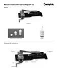
Push-On Tool
Mandrels (3 short, 2 medium, 2 long)
Lubricant
Push-On Tool Components
Pusher handle
Jaws
Pusher
Mandrel
Vise
Vise handle
Limiting spring
Mounting holes
(6)
Preparation
5.Select the appropriate mandrel according to the table.
1.Use six 3/8 in. bolts or a clamp to attach the tool to a
workbench. (Bolts and clamp are not provided).
Hose Type
Rubber
Nylon and
Polyethylene
2.Line up the flats of the vise handle to the tool and push
the handle on until it stops. Thread the set screw into the
handle and tighten with a 1/8 in. hex key.
3.Inspect the tool and jaws for wear. Replace the jaws if
excessive wear is observed. (The jaws will be rough to
the touch.)
Nominal Hose Size,
in.
Recommended
Mandrel Size
1/4, 3/8, 1/2
Long
3/4
Medium
1
Short
1/4, 3/8
Long
1/2
Medium
3/4, 1
Short
6. For assemblies using tube fitting end connections (-SL
and -SM designators), verify that the nut and ferrules are
installed prior to pushing the end connection onto the
hose. Install if necessary.
Nuts and Ferrules
Nuts and Ferrules
Not InstalledInstalled
7. Place the pusher handle in the down position.
8. Verify that the limiting spring is installed.
9. Thread the selected mandrel into the end of the pusher
fingertight.
Note: T
he short mandrel is installed at the factory.
Remove it from the pusher if a different size is
needed.
Mandrel
4. Lubricate the tool shaft in the locations shown with the
provided lubricant prior to initial use and approximately
every 500 assemblies or once per week. Cycle the
handle several times after applying the lubricant.
Apply lubricant here.
Pusher
Limiting
spring
10. Ensure that the hose end is properly cut using a hose
cutting tool (must be ordered separately).
Insertion of End Connection onto Hose
Note: T
he handle should not be moved to the fully
back position. This will cause the tool to wear
prematurely.
Cutting tool ordering numbers:
■ MS-FT-TC for rubber hose up to 3/4 in. nominal
size.
C-ELD-0525B
■ MS-HC-SC-1 for nylon, polyethylene, or rubber
C-ELD-525A
hose up to 1 in. nominal size.
Proper cut
1. Raise the pusher handle approximately 90°.
Improper cut
11.Nylon and Polyethylene hose:
Place one end of the hose into the appropriate hole on a
depth insertion gauge (must be ordered separately), until
it bottoms out.
Gauge ordering numbers:
■ MS-IGB-1 for 1/4, 3/8, and 1/2 in. hose.
■ MS-IGB-2 for 3/4 and 1 in. hose.
2. Turn the vise handle counterclockwise to open the jaws
until the hose can pass through freely.
Mark the hose with a sharp grease pencil as close to the
gauge as possible.
Note: T
he bottom of the mark should line up with the top
of the insertion gauge.
C-ELD-526A
Proper mark position
C-ELD-526B
Improper mark position
Note: T
he handle may have a higher initial actuation
torque if it is new or has not been turned for a
period of time.
3. Use the end connection as a gauge and slip the hose
through the jaws until the hose sticks out the length
of the barbs or shell on the end connection plus
approximately an additional 1/2 inch (12.7 mm).
1/2 inch approx.
(12.7 mm)
For additional information, see the Swagelok Hose and
Flexible Tubing catalog, MS-01-180.
4. Turn the vise handle clockwise to close the vise until
the jaws just hold the hose in place. Turn the handle an
additional 1/4 to 1/2 turn to secure the hose.
Note: If the hose still moves, repeat steps 3 and 4,
tightening the vise handle until the hose is secure.
7. Hold the hose in line with the end connection and lower
the pusher handle to push the end connection into
the hose until the end connection is inserted properly
according to the table below.
CAUTION
There is a potential pinch point between the end
of the hose and the finishing cap / divider tab.
Hose Type
Insertion Criteria
Rubber, up to 1 in. hose size
Hose seats into the blue
finishing cap
Rubber, 1 in. hose size
Hose seats flush with the
divider tab
Nylon and Polyethylene
Bottom of the insertion mark
lines up with the edge of the
end connection.
If the hose is not properly inserted, open the jaws, and
repeat Insertion of End Connection onto Hose steps 3, 4,
6, and 7.
5. Insert the first barb of the end connection into the hose.
6. Lower the pusher handle until the mandrel meets the end
connection.
Replaceable Component
Note: T
he recommended method is to fully open the jaws
and unload from the top. Larger hose sizes will
have to be pulled through the jaws to be removed.
Ordering Number
Push-On tool
MS-SPOT
Mandrel kit
MS-SPOT-MKIT
Jaws
MS-SPOT-JAW-KIT
Lubricant
MS-TP-LUBE
Translations available on
www.swagelok.com.
8. Raise the pusher handle and open the jaws to remove the
hose.
Swagelok — TM Swagelok Company
© 2011 Swagelok Company
July 2011, R1
MS-CRD-0190