1
Installation
3.4
Connections to the Vision
90
Proceed as follows to connect the Vision 90 to your video sources, external controller(s) -- if
present -- and AC power.
When connecting your equipment:
• Turn off all equipment before making any connections.
• Use the correct signal cables for each source.
• Ensure that the cables are securely connected. Tighten the thumbscrews on connectors
that have them.
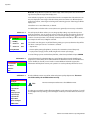
Connector Panel Access ➤
Connect your video sources to the Vision 90 as shown and described in the sections that
follow.
DVI Connections: See Figure 3-7.
Use the DVI inputs whenever possible. This ensures the highest video
quality because the signal is carried in the digital domain throughout the
entire signal path, from source component output into the projector.
INPUTS
INPUTS
Pb
B
H
Tip
V
Y
G
Pr
R
TRIGGERS
HD1
TRIGGERS
HD1
1
2
3
IR
1
2
3
IR
HD2
HD2
B
Pb
DVI 1
DVI 2
DVI 2
V
Y
Pb
Pr
COMPONENT VIDEO
DVI 1
H
S-VIDEO 1
VIDEO
G
Y
S-VIDEO 1
R
Pr
RS-232
CONTROL
S-VIDEO 2
Connecting the Vision 90 to ➤
Source Components
To access the connector panel, press the
large, black door release button so it pops
out. Then, turn the knob clockwise or
counter-clockwise and pull gently on it to
open the door.
S-VIDEO 2
Pb
Pr
Y
COMPONENT VIDEO
VIDEO
RS-232
CONTROL
DVI Source
(DVD Player or
HD Tuner with
HDMI or DVI out)
Figure 3-7. DVI Source Connections
3-10
Vidikron Vision Model 90 Owner’s Operating Manual