1
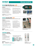
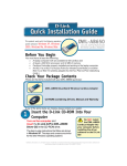
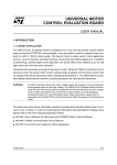
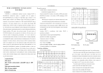
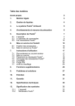
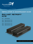
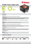
®
AirCraft ,
®
®
AirGuard , AirPro
™
& QuietDry
Dryer Guide
Effective 08/13
All Bobrick dryers require cleaning every 6 months to ensure
that they function effectively. Please note that failing to clean
the dryer may result in malfunction and can void the warranty.
(Refer to page 3 of the Dryer Troubleshooting and Information Guide for Routine Maintenance Instructions)
www.bobrick.com
U.S. Headquarters: BOBRICK WASHROOM EQUIPMENT, INC.
11611 Hart Street, North Hollywood, California 91605-5882, Tel: 818.982.9600, FAX: 818.503.1102
Email: [email protected]
Canada Headquarters: BOBRICK WASHROOM EQUIPMENT COMPANY.
45 Rolark Drive, Scarborough, Ontario M1R 3B1, Eastern: 877.423.6555, FAX: 877.423.8555, Western: 877.423.6444,
FAX: 877.423.8444, Email: [email protected]
International Sales: BOBRICK WASHROOM EQUIPMENT, INC.
11611 Hart Street, North Hollywood, CA 91605-5882, +1.818.764.1000, FAX: +1.818.503.9941
Email: [email protected]
Australia: Bobrick Washroom Equipment Pty Ltd., 1.800.353158, FAX: 1.800.221926
Email: [email protected]
Germany: 0800.79.00.456, FAX: 0800.79.00.789 Email: [email protected]
United Kingdom: Bobrick Washroom Equipment Ltd., +44.0.20.8366 1771, FAX: +44.0.20.8363.5794.
Email: [email protected]
AirCraft_DTG r8-13
Page 1 of 28
AirCraft®, AirGuard®, AirPro® & Fast Dry Dryers
Contents
Page
1. Cover removal
5
2. Diagnostic Sheet
6
3. Field Replacement Parts
9
4. Installation Instructions
12
5. Product Identification
3
6. Schematic Diagrams
26
7. Screwdriver Test
8
8. Warranty
25
AirCraft_DTG r8-13
Page 2 of 28
Product Identification
AirCraft® Dryers
Surface-Mounted Dryers:
B-700 Automatic Hand & Face (pictured)
B-701 Touch Button Hand & Face
B-731 Touch Button Hair
Recessed Dryers:
B-750 Automatic Hand & Face (pictured)
B-751 Touch Button Hand & Face
B-781 Touch Button Hair
AirCraft_DTG r8-13
Page 3 of 28
AirGuard® Dryer
B-708 Automatic
Series Variations:
Series G
lower profile cover, no nameplate
or printing. (pictured)
Not all replacement parts are interchangeable, see parts list.
AirPro® Dryer
B-709 Touch Button
B-709 Automatic (pictured)
Series Variations:
Series A
Series B
Series C
touch button model, metal
nameplate.
automatic model, metal nameplate.
automatic model, lower profile cover, no nameplate.
Not all replacement parts are interchangeable, see parts list.
QuietDry Dryer
B-770 White cover
B-778 Chrome cover
AirCraft_DTG r8-13
Page 4 of 28
Instructions For Removal Of Dryer Cover
Warning
Risk of electric
shock
Disconnect power
supply before
removing cover
To Remove Cover
Locate the two tamper resistant screws at the bottom of the dryer cover.
Using the Allen-wrench (4 or 5mm), turn the screws clockwise to loosen the cover. Do
not take the screws out, the screws have to be done up to loosen the cover.
Lifting the cover over the two latches at the top of the chassis, remove the cover.
To Replace Cover
Place the cover over the two latches located at the top of the chassis. Make sure that
the cover has a good fit.
Using the Allen-wrench, turn the screws counter clockwise loosening the screws which
will tighten the cover onto the chassis. Do not over tighten screws.
Check to make sure the cover has a good fit. Turn power back on to the dryer unit.
AirCraft_DTG r8-13
Page 5 of 28
Diagnostic Sheet For AirCraft®, AirGuard®, AirPro®
& QuietDry™ Dryers.
Problem
Possible Cause
Possible Solution
a) No electricity supply
b) Installation fault
Check main supply / wiring
Check service manual for possible
wiring mistakes
Check length of brushes; replace if
less than ½”
Return dryer to Bobrick for repair
Replace control
Replace triac
Replace motor brushes
Replace motor brushes
Remove white wire from triac; no
difference, replace triac
Remove white wire from triac; dryer
stops, replace control
Remove white wire from triac; no
difference, replace triac
Remove white wire from triac; dryer
stops, replace control
Replace control
Clean control lens
Replace control
Replace control
Return dryer to Bobrick for repairs
AUTOMATIC
1. Dryer does not run
c) Worn motor brushes
2. Sparks from dryer
3. Dryer runs at low speed
d) Element open circuit
e) Control nonstart
f) Triac open circuit
Worn motor brushes
a) Worn motor brushes
b) Triac halfwave
c) Control halfwave
4. Dryer runs continuously
a) Triac short circuit
b) Control faulty
5. Dryer cycles on and off
6. Dryer sometimes runs
7. Dryer is oversensitive
8. Dryer blows cold air or
motor runs fast
9. Grinding noise from dryer
10. Dryer does not run and
heating element glows
Control
Dirty control lens
Control
Control
Heating element
a) Worn motor brushes
b) Fan cage is bent or
damaged
Worn motor brushes
Replace motor brushes
Return dryer to Bobrick for repairs
a) No electricity supply
b) Installation fault
Check main supply / wiring
Check service manual for possible
wiring mistakes
Turn off power, remove cover and
bend tabs closer to sensor board
Check length of brushes; replace if
less than ½”
Return dryer to Bobrick for repair
Perform Screwdriver Test (see test
instructions)
Replace motor brushes
Replace motor brushes; if still not
functioning after replacing the motor
brushes, return dryer to Bobrick for
repairs.
Replace motor brushes
Replace motor brushes; if still not
functioning after replacing the motor
brushes, return dryer to Bobrick for
repairs.
TOUCHBUTTON
1. Dryer does not run
c) Tabs are not connecting
d) Worn motor brushes
e) Element open circuit
f) Timer assembly nonstart
2. Sparks from dryer
3. Dryer does not run and
heating element glows
Worn motor brushes
Worn motor brushes
4. Dryer runs at low speed
a) Worn motor brushes
AirCraft_DTG r8-13
Page 6 of 28
Problem
Possible Cause
Possible Solution
5. Dryer runs continuously
6. Dryer blows cold air
b) Timer assembly
b) Timer assembly
Heating element
a) Worn motor brushes
Replace timer assembly
Replace timer assembly
Return dryer to Bobrick for repair
Replace motor brushes
b) Fan cage is bent or
damaged
a) Button loose
Return dryer to Bobrick for repair
b) Timer assembly or crystal
board
Timer assembly or crystal
board
Perform Screwdriver Test (see test
instructions)
Perform Screwdriver Test (see test
instructions)
7. Grinding noise from dryer
8. Dryer is oversensitive and
switches on or off randomly
9. Dryer cycles on and off
AirCraft_DTG r8-13
Pack button O ring with tape
Page 7 of 28
Screwdriver Test for Touch Button Dryers
Warning
Risk of electric
shock
Disconnect power
supply before
removing cover
NOTE: This test instruction sheet is not for dissemination to, and should not be
disseminated to, the public including end users.
This test is designed to test the Touch Timer Assembly and the Sensor Board.
Instructions For Test:
1.
Turn off the power to dryer.
2.
Remove dryer cover.
3.
Turn on the power. Do not touch any part of the dryer.
4.
Using an insulated screwdriver, short across the two tabs (see below).
a) If dryer runs ...................sensor board may be faulty ......... replace sensor board.
b) If dryer does not run ......timer may be faulty ...................... replace touch
controller.
5.
Turn off power to dryer.
6.
Put dryer cover back on and turn power on.
AirCraft_DTG r8-13
Page 8 of 28
Field Replacement Parts
•
Replacement parts are intended to be issued by Bobrick after completion of
diagnostic sheets and a problem is identified that involves replacement of parts.
•
Replacement parts will then be sold to the customer/rep with credit issued upon the
return of identifiable malfunctioning and/or unused parts.
•
A copy of the Dryer Service Information Sheet must be completed by the rep and
sent to Bobrick prior to return of parts.
•
Dryer voltage must be identified in order to replace parts. Replacement parts have
options for both the 115V and 208–240V dryers. Check voltage and then designate
correct part(s).
AirCraft® Dryer Replacement Parts
AirGuard®, AirPro® & QuietDry Dryer Replacement Parts
AirCraft_DTG r8-13
Page 9 of 28
AirCraft® Dryer Replacement Parts
Surface touch
Surface automatic
115V
208-240V
Touch controller
hand & face
701-360
Touch controller
hair
Sensor Board
115V
208-240V
701-361
701-360
701-361
731-360
731-361
731-360
731-361
701-138
701-138
701-138
701-138
Automatic
controller
Air Outlet Grille
& Seal
Covers
701-120
701-120
115V
Recessed touch
208-240V
700-360
700-361
700-120
700-120
701-120
701-120
Recessed automatic
115V
208-240V
750-360
750-361
700-120
700-120
Model code without the B followed by -150, voltage and then color
code.
Voltage:
115V
230V
Color codes:
Almond
Black
Grey
Ivory
White
#885
#828
#889
#848
no code
Eg. 7007-150 115V #828
Model B7007, voltage 115V, color Black.
Common Parts
Triac
700-325
Motor Brushes EMD (Red Retainer)
700-101
Motor Brushes Sintech (Brass Retainer)
700-111
Motor Brushes Ametek & Winston
700-121
Cover Mounting Screws
700-156
Allen Wrench
700-55
Wall Box (Recessed Dryers Only)
700-506
Brush identification
The following items are not to be field replaced:
Motor/fan units.
Heating elements.
AirCraft_DTG r8-13
28
Page 10 of
AirGuard®, AirPro® & QuietDry™ Dryer
Replacement Parts
115V
208-240V
Touch controller
701-360
701-361
Sensor Board
701-138
701-138
Automatic controller
700-360
700-361
Air Outlet Grille & Seal
701-120
701-120
B-708 Series A – F cover
708-150 115V
708-150 230V
B-708 Series G cover
708G-150 115V
708G-150 230V
B-709 Series A cover
709-150 115V
709-150 230V
B-709 Series B cover
709B-150 115V
709B-150 230V
B-709 Series C cover
709C-150 115V
709C-150 230V
B-770 White cover
770-150 115V
770-150 230V
B-778 Chrome cover
778-150 115V
778-150 230V
QuietDry Controller
770-360
770-361
Product Identification
Common Parts
Triac
700-325
Motor Brushes EMD (Red Retainer)
700-101
Motor Brushes Sintech (Brass Retainer)
700-111
Motor Brushes Ametek & Winston
700-121
Cover Mounting Screws
700-156
Allen Wrench
700-55
Brush identification
The following items are not to be field replaced:
Motor/fan units.
Heating elements.
AirCraft_DTG r8-13
28
Page 11 of
Installation Instructions
Installation Instructions
Page
Cover Replacement
13
Installation Of Touch Controller
14
Installation Of Base Plate Mounted Triac
15
Installation Of Automatic Controller
16
Instructions For Installation Of Sensor Board
17
Instructions For The Replacement Of Motor Brushes
18
Installation of Surface-Mounted Hand and Hair Dryers
19
®
Installation of Recessed AirCraft Hand and Hair Dryers
22
AirCraft_DTG r8-13
28
Page 12 of
Cover Replacement
The dryer covers for
different models are NOT
interchangeable.
Warning
Risk of electric
shock
Disconnect power
supply before
removing cover
Fig 1
Fig 1A
Fig 2
Fig 1B
Fig 2
Fig 2A
To Remove Cover
1.
2.
3.
4.
Disconnect the power supply.
Locate the two tamper resistant screws at the bottom of the dryer cover.
Using the Allen-wrench (4 or 5mm), turn the screws clockwise to loosen the cover.
Lifting the cover over the two latches at the top of the chassis, remove the cover.
To Replace Cover
1. Place the cover over the two latches located at the top of the chassis. Make sure that
the cover has a good fit.
2. Using the Allen-wrench, turn the screws counter clockwise loosening the screws; this
will tighten the cover onto the chassis. Do not over tighten the screws.
3. Check to make sure the cover has a good fit. Turn the power supply back on.
4. Allow 10 seconds for the controller to stabilize and check operation of the dryer. On
Automatic Dryers if the operation is intermittent check that the controller has a clear
view out of the cover aperture, use the spacers provided to raise the controller if
required.
AirCraft_DTG r8-13
28
Page 13 of
Installation Of Touch Controller
To Remove Existing Timer
1. Disconnect the power supply and remove the cover.
2. Remove the timer from the base plate by unscrewing the two screws securing the timer bracket to the
base. On recessed dryers the timer bracket is secured to a metal angle bracket, this bracket with its
screws must be removed and retained for use on the replacement timer.
3. Disconnect the pink or yellow, red, and black timer wires from the terminal block and the white wire
push on connector from the triac (115V only). Place the timer aside for return to the Service
Department.
To Install New Timer
1. Mount the timer assembly to the base plate . In the case of recessed dryers, it is first necessary to
attach the metal angle bracket removed from the faulty timer to the new timer.
2. Route the timer wiring under the element tube and attach the white wire push on connector to the
small spade terminal on the triac (115V only), older 208 – 240V units may have a base plate mounted
triac, this is no longer required and can be removed.
3. Connect the remaining three timer wires to the terminal block, black wire to terminal 1, red wire to
terminal 2, pink wire to terminal 3.
4. Secure wiring with cable ties provided.
5. Replace dryer cover. Switch on electrical supply and test
operation.
Warning
Risk of electric
shock
AirCraft_DTG r8-13
28
Disconnect power
supply before
removing cover
Page 14 of
Installation Of Base Plate Mounted Triac
Note: This procedure applies only to surface-mounted or recessed
dryers with triac mounted on the base plate. For touch button models
with triac mounted on the timer bracket, the complete timer assembly
must be replaced.
Warning
Risk of electric
shock
Disconnect power
supply before
removing cover
To Remove Existing Triac
1. Disconnect power supply and remove cover.
2. Remove white, yellow or pink, and black Push On connectors from triac.
3. Remove the two screws securing the triac to the base plate.
4. Remove the triac and place to one side for return to Service Department.
To Install New Triac
Note: On factory-installed triac, a white Heat sink Compound is interposed between the triac flange and the
dryer base plate to ensure rapid conductivity of heat away from the triac. For service purposes this compound
is replaced by a thin plastic gasket of heat conducting material, this must be sandwiched between the flange
and the base plate during assembly.
1. Position new triac and pad on base plate with the Terminals positioned as shown in illustration below.
Insert and tighten the two self-threading screws and shake proof washers provided.
2. Attach the white wire Push On
connector to the small spade
Terminal on the triac. The black
wire from the Terminal Block
should then be attached to the
next Terminal round in a
clockwise direction and the
yellow or pink wire to the
remaining Terminal.
3. Replace dryer cover. Switch on
electrical supply and test
operation, allow 10 seconds for
the controller to stabilize before
placing hands in front of lens
(automatic units).
AirCraft_DTG r8-13
28
Page 15 of
Installation Of Automatic Controller
Warning
Risk of electric
shock
Disconnect power
supply before
removing cover
Older units have an intermediate plug and socket in the wiring, this has now been discontinued and can be
removed with the faulty controller. The wiring on older units may be sleeved, this was later replaced by plastic
cable ties. Some early 115 volt dryers had 4 way terminal blocks instead of the current 3 way blocks, in these
th
dryers the wires to the 4 terminal should not be disturbed.
To Remove Control Unit
1. Remove outlet grille from front of fan case by unscrewing the securing
screws.
2. Remove the screws securing the control unit to the base plate. (Note
the different position of recessed and surface-mounted screws).
3. If the control unit wiring is secured by cable ties, carefully cut these to
free the 4 wires from other wiring.
4. Remove the Push On Terminal securing the white wire to the triac.
5. Disconnect the controller wires from terminals 1, 2, and 3 on the
terminal block. Leave all other wires in position.
6. Carefully lift control out of base plate. Avoid disturbing other wiring.
(Note: On recessed dryers it will be necessary to slide the control to the
right to clear the fan case).
To Install New Control Unit
1. Position the new control unit on the base plate to line up with the screw
holes and secure with the screws and washers previously removed.
2. Route wiring under element tube and connect wiring as follows: white
wire with Push On Terminal to triac. Black wire to Terminal 1 (with
existing black wire). Red wire to Terminal 2 (with existing red wire).
Pink wire to Terminal 3 (with existing wiring).
3. Secure all wires to existing wires with a minimum of 2 cable ties.
4. Replace grille and sealing gasket and secure with screws previously
removed.
5. Check all wires for security and all screws for tightness.
6. Replace cover. Switch on electric supply.
7. Allow 10 seconds for the controller to stabilize and check operation of
the dryer. If the operation is intermittent check that the controller has a
clear view out of the cover aperture, use the spacers provided to raise
the controller if required.
AirCraft_DTG r8-13
28
Page 16 of
Instructions For Installation Of Sensor Board
There are two methods fixing sensor boards.
1. Fixed with five screws, Fig 1.
2. Fixed with three screws, Fig 2.
Warning
Risk of electric
shock
Disconnect power
supply before
removing cover
Fig 1
In both cases the orientation of the board is critical.
Fig 2
1. Switch off mains supply and remove cover. Place cover face downward on a bench using a cloth to
protect the finish.
2. Remove the screws securing the board to the collar or bracket.
3. Mount the new board.
4. Replace cover. Switch on electrical supply and carry out normal hand drying procedure to test
operation.
AirCraft_DTG r8-13
28
Page 17 of
Instructions For The Replacement
Of Motor Brushes
Warning
Risk of electric
shock
Disconnect power
supply before
removing cover
The brush spares kit contains two brushes.
Always replace BOTH brushes.
EMD MOTOR
To remove the brush:
1. Squeeze the sides of the retainer and ease it
over the stud with a small screwdriver.
2. Remove the retainer, cap and brush. Do not
mislay the small cap spring.
To replace the brush:
1. Insert the new brush into the holder.
2. Place the cap, with the cap spring inside it,
over the brush spring and press it over the
holder.
3. Slide the retainer down the cap and snap it
into position over the stud.
SINTECH MOTOR
On this motor the brush is replaced by changing
the complete brush box assembly.
To remove the brush box assembly:
1. Pull the connector off the terminal tab, (A).
2. Depress the retaining tab with a small
screwdriver and pull out the brush box, (B)
and (C).
To replace the brush box assembly:
1. Insert the new brush box and push it down
until the retaining tab is level with the slot in
the motor end frame.
2. Bend out the retaining tab.
3. Replace the connector on the terminal tab.
AMETEK & WINSTON MOTORS
On this motor the brush is replaced without
disturbing the brush box.
To remove the brush:
1. Depress the locking tab in the connector with
a small screwdriver, (A).
2. Slide out the connector and remove the brush,
(B) and (C).
To replace the brush:
1. Insert the new brush into the holder.
2. Press the spring down with a screwdriver until
it is below the connector slot, (D).
3. Push the connector into the slot until it locks
into position, (E). Make sure that all of the top
coil is under the connector.
AirCraft_DTG r8-13
28
Page 18 of
INSTALLATION INSTRUCTIONS BOBRICK
SURFACE-MOUNTED HAND DRYERS
ELECTRICAL CHARACTERISTICS.
115V AC, 20 Amp, 50/60 Hz, Single Phase, UL/c-UL listed.
208–240V AC, 9–10 Amp, 50/60 Hz, Single Phase, UL/c-UL listed, VDE approved.
REMOVAL OF COVER
Start installation of dryer by removing cover. To loosen two cover bolts insert Allen Wrench,
provided with dryer, into holes located on bottom of cover on each side of air intake grille.
Make sure wrench fits into head of cover bolts and turn CLOCKWISE until bolts stop
turning. When cover bolts are screwed in all the way, cover can be removed.
To remove cover, place a hand on each side of cover and push up toward top of dryer
releasing cover from studs at top of mounting base. Lift cover off mounting base by pulling
forward at the bottom and upward at the same time.
INSTALLATION OF MOUNTING BASE.
An Installation Template is supplied with each unit.
RECOMMENDED MOUNTING HEIGHTS.
Distance from floor to bottom mounting screw holes of mounting base (Dimension A).
Hand dryer.
Men’s Washrooms ................................................................. 46'' (117cm)
Women’s Washrooms ........................................................... 44'' (112cm)
Children’s Washrooms, ages 3-9 .......................................... 32'' (81cm)
Page 19
Children’s Washrooms, ages 9-12 ........................................
Children’s Washrooms, ages 12-15 ......................................
Children’s Washrooms, ages 15-18 ......................................
For Wheelchair Access .........................................................
36'' (91cm)
40'' (102cm)
44'' (112cm)
38'' (97cm)
Place mounting base on wall at the desired location of the installed dryer. See
recommended mounting heights above. Use the mounting base or the template provided
with dryer to mark location of four mounting screw holes and hole for electrical wiring if
electrical supply is concealed in wall and will enter dryer from back through mounting base.
NOTE: Surface-mounted electrical supply is attached to mounting base in lower right
corner. Flange of mounting base and bottom of cover are notched in lower right corner to
accommodate connection of electrical conduit.
WARNING:
TURN ELECTRICAL POWER SUPPLY OFF BEFORE MAKING ELECTRICAL
CONNECTIONS.
DRYER MUST BE GROUNDED (EARTHED).
ELECTRICAL CONNECTION.
Connect dryer to nearest distribution panel. Use wire as required by local electrical code. In
the United States and Canada use No. 12 wire or larger.
Wiring Instructions:
For 115 Volt Dryers: Connect ground (earthed) wire to ground (earthed) terminal marked
, the black or Hot wire to terminal marked L1 and neutral or white wire to terminal
marked N.
DEDICATED LINE IS REQUIRED FOR EACH 115 VOLT DRYER.
For 208–240 Volt Dryers: Connect ground (earthed) wire to ground (earthed) terminal
marked
and the 208-240 Volt wires to terminals marked L(L1) and N (L2).
Secure electrical wire in strain relief clamp provided on mounting base.
REPLACE COVER.
Replace cover by positioning top of cover on studs on top of mounting base and tipping
bottom of cover toward wall. Push bottom of cover firmly against wall.
NOTE: Space between cover and wall must be the same on four sides.
To tighten two cover bolts, insert Allen wrench into holes on bottom of cover. Make sure
wrench fits into head of cover bolts and turn COUNTERCLOCKWISE until bolts are
tightened.
NOTE: Do not over tighten cover bolts; over tightening cover bolts may damage enamel
finish.
CHECK DRYER OPERATION.
To check operation of dryer, follow these instructions:
Page 20
For Touch Button Hair Dryers: Turn electrical power supply on. Touch the chrome-plated
touch button once and dryer should turn on. Touch the touch button again after a few
seconds and dryer should stop. If left on Hair Dryers will shut off after 80 seconds.
For Automatic Hand Dryers: Turn electrical power supply on. Position hands under nozzle
and dryer should turn on. Remove hands from under nozzle and dryer should stop.
Page 21
INSTALLATION INSTRUCTIONS BOBRICK RECESSED
AIRCRAFT® HAND DRYERS
ELECTRICAL CHARACTERISTICS.
115V AC, 20 Amp, 50/60 Hz, Single Phase, UL/c-UL listed.
208–240V AC, 9–10 Amp, 50/60 Hz, Single Phase, UL/c-UL listed, VDE approved.
INSTALLATION OF RECESSED MOUNTING BOX.
An Installation Template is supplied with each unit.
RECOMMENDED MOUNTING HEIGHTS.
Distance from floor to bottom of framed wall opening (Dimension A).
Hand dryer
Men’s Washrooms .................................................................
Women’s Washrooms ...........................................................
Children’s Washrooms, ages 3-9 ..........................................
Children’s Washrooms, ages 9-12 ........................................
Children’s Washrooms, ages 12-15 ......................................
Children’s Washrooms, ages 15-18 ......................................
For the Handicapped .............................................................
46'' (117cm)
43'' (109cm)
31'' (79cm)
35'' (89cm)
39'' (99cm)
43'' (109cm)
38'' (97cm)
Provide framed opening in wall 13-3/4'' wide x 9-1/2'' high x 3-3/4'' deep (349 x 241 x
95mm) at the desired location of the installed dryer. See recommended mounting heights
above.
Frame the opening as shown in diagram to support recessed mounting box.
Place the recessed mounting box in wall and cut an opening in the framing to allow
clearance for electrical conduit and fittings at one of the three conduit knockout locations.
Page 22
Fasten recessed mounting box to framing with minimum of four No. 10 (4.8mm) sheet metal
screws (not furnished by Bobrick). Make sure flanges of mounting box are completely flat
against finished wall surface. If necessary, use shims or spacers between mounting box
and framed wall opening to prevent distortion to box as it is fastened to framing.
Install electrical conduit from nearest distribution panel to recessed mounting box. Attach
conduit fittings to mounting box. Use wire as required by local electrical code. In the United
States and Canada use No. 12 wire or larger. Allow a minimum of 24'' (610mm) of wire to
remain in recessed mounting box for connection to dryer terminals.
INSTALLATION OF ALUMINUM BASE UNIT INTO RECESSED MOUNTING BOX.
Start installation of aluminum base unit into recessed mounting box by removing cover. To
loosen two cover bolts, insert Allen wrench, provided with dryer, into holes located on
bottom edge of cover. Make sure wrench fits into head of cover bolts and turn CLOCKWISE
until bolts stop turning. When both cover bolts are screwed in all the way, cover can be
removed.
To remove cover, place a hand on each side of cover and push up toward top of dryer
releasing cover from studs at top of aluminum base unit. Lift cover off base unit by pulling
forward at the bottom and upward at the same time.
Insert aluminum base unit into recessed mounting box and fasten to top and bottom flanges
of mounting box with the four 1/4-20 UNC (MG-1) screws provided.
WARNING:
TURN ELECTRICAL POWER SUPPLY OFF BEFORE MAKING ELECTRICAL
CONNECTIONS.
DRYER MUST BE GROUNDED (EARTHED).
ELECTRICAL CONNECTION.
Wiring Instructions:
For 115 Volt Dryers: Connect ground (earthed) wire to ground (earthed) terminal marked
, the black or Hot wire to terminal marked L1 and neutral or white wire to terminal
marked N.
DEDICATED LINE IS REQUIRED FOR EACH 115 VOLT DRYER.
For 208–240 Volt Dryers: Connect ground (earthed) wire to ground (earthed) terminal
marked
and the 208-240 Volt wires to terminals marked L(L1) and N (L2).
Make sure excess wire does not interfere with operation of dryer.
REPLACE COVER.
Replace cover by positioning top of cover on studs on top of aluminum base unit and
tipping bottom of cover toward aluminum base. Push bottom of cover firmly against base.
NOTE: Space between cover and base must be the same on bottom and both sides.
To tighten two cover bolts, insert Allen wrench into holes on bottom edge of cover. Make
sure wrench fits into head of cover bolts and turn COUNTERCLOCKWISE until bolts are
tightened. NOTE: Do not over tighten cover bolts; over tightening cover bolts may damage
enamel finish.
CHECK DRYER OPERATION.
Page 23
To check operation of dryer, follow these instructions:
For Automatic Hand Dryers: Turn electrical power supply on. Position hands under nozzle
and dryer should turn on. Remove hands from under nozzle and dryer should stop.
Page 24
LIMITED WARRANTY
The Bobrick Dryer and all parts (except motor brushes) are warranted to the original owner
of the installed unit for ten years from date of original installation for AirCraft® and AirGuard®
Automatic and Touch Button hand and hair dryers and five years for AirPro® and Fast Dry
hand dryers, against defects in factory workmanship or material under normal use and
service. *
Motor brushes shall be warranted for three years from date of installation. This warranty is
limited to repair or exchange of defective parts at the option of Bobrick Washroom
Equipment, Inc.
THIS WARRANTY DOES NOT COVER ACCIDENTAL DAMAGE, IMPROPER
HANDLING OR INSTALLATION, OR REPAIRS MADE BY UNAUTHORIZED PERSONS,
AND SPECIFICALLY EXCLUDES CLAIMS FOR INDIRECT, ACCIDENTAL OR
CONSEQUENTIAL DAMAGES TO PROPERTY. THE IMPLIED WARRANTIES OF
MERCHANTABILITY AND FITNESS FOR A PARTICULAR PURPOSE ARE LIMITED TO
THE SAME DURATION OF THE ABOVE WARRANTY.
Some states do not allow the exclusion of incidental or consequential damages, so the
above limitation or exclusion may not apply to you. Some states do not allow limitations on
how long an implied warranty lasts, so the above limitation may not apply to you. This
warranty gives you specific legal rights, and you may also have other rights which vary from
state to state.
* Normal service constitutes performing the following preventive maintenance
procedures at six-month intervals.
Remove cover and clean any lint, dust or grease from air-intake grille and baffle from
behind air-outlet nozzle.
Visually inspect motor brushes to insure remaining brush length is a minimum of 1/2
inch (12.7mm).
Labor costs for preventive maintenance shall be at owner's expense.
For repair or exchange of defective part, send the part, together with installation date and
serial number, to BOBRICK.
Page 25
Schematic Diagram
115V Dryer
Schematic Diagram
208-240V Automatic Dryer
Page 26
Schematic Diagram
208-240V Touch Dryer
Page 27
Schematic Diagram
QuietDry Dryers
115V
208-240V
C - Cutout
H – Heater
M – Motor
TS – Timer/Sensor
Page 28