1
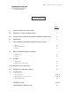
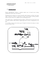
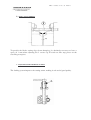
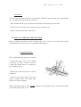
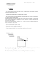
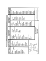
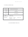
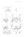
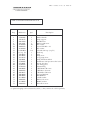
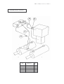
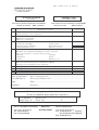
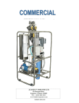
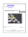
EPM3 11334008 / 01-02 / 07
PAGE 1
WIDE HYDRAULIC RAIL WELD SHEARING MACHINE EPM3
INTEGRAL TYPE WITH HAND PUMP
REF. 1 1 3 3 4 0 0 8
OPERATING AND MAINTENANCE MANUAL
REVISION 00
EDITION 02-2007
RAILTECH INTERNATIONAL
Siège Social et Usine : Z.I. du Bas Pré – B.P. 9 – 59590 RAISMES – FRANCE- Tél. : 33 (0) 3.27.22.26.26 - Fax : 33 (0) 3.27.22.26.00
Direction Générale et Commerciale 119, Avenue Louis Roche – BP 152 - 92213 GENNEVILLIERS Cedex – France
Tel 33.1.46 88 17 00 – [email protected] - Fax 33.1.46 88 17 01 et 17 66
EPM3 11334008 / 01-02 / 07 PAGE 2
CONTENTS
Pages
I
SAFETY LABELS EXPLANATION
3
II
GENERAL SAFETY INSTRUCTIONS
3
III
SAFETY MEASURES TO BE TAKEN PRIOR TO INITIAL USE
3
IV
PRINCIPLE
4
V
ADJUSTMENTS BEFORE STARTING THE MACHINE
1 - Blades
2 - Stops adjustments
3 – Locks
VI
HOW TO OPERATE THE MACHINE
1 - Mold release
2 - Cutting
VII
5
6
6
7
8
BLADES
1 - Sharpening
2 - Differents profiles blades
8
9
VIII HYDRAULICAL DIAGRAM
10
IX
TECHNICAL SPECIFICATIONS
11
XI
SPARE PARTS
1 - Shearing unit
2 - Pump support crosspiece suit
3 - Hydraulical fitting
13 & 14
15 & 16
17
CONTROL CARD
18 & 19
CONFORMITY CERTIFICATE
20
EPM3 11334008 / 01-02 / 07
PAGE 3
I – SAFETY LABELS EXPLANATION
WARNING ! The machine can be dangerous.
Careless and incorrect use can result in injury
to the operator
Read carefully the instructions of the
operating manual and make sure you
understand them before using the machine.
WARNING ! Be carefull to the mobile pieces
of the shearing machine so as to avoid any risk of
squashing
II – GENERAL SAFETY INSTRUCTIONS
* Do not use the shearing machine until you have read and understood the entire contents
of the operator's manual
* The shearing machine is specially designed to cut off the metal excess, or deadhead,
generated by rail aluminthermic welding, never use this machine for any other work
* Never use the shearing machine when you are tired, under the influence of medicines,
alcohol or any substance that can affect your perception, dexterity or your appreciation
capacity
* Do not mix different types of oil.
III - SAFETY MEASURES TO BE TAKEN PRIOR TO INITIAL USE
* Chek that all hydraulic pipes are correctly positioned so as to avoid their shearing or a
contact with the weld
* To obtain high performances and get most satisfaction with the shearing machine,
realise the different adjustments recommended with a particular attention before starting
the machine
EPM3 11334008 / 01-02 / 07 PAGE 4
IV - P R I N C I P L E
During aluminothermic welding, a deadhead which serves of metal reserve during
solidification remains above the rail head.
Traditionally this deadhead was removed manually with a hammer and chisel, hard work
which exposed the workers to projections of metal. The hydraulic shearing machine
allows to cut the metal excess without any risk of damaging the rail.
After mould release, 2 hydraulically operated blades, guided by the rail itself, move and
cut off the deadhead. This machine is lightweight and can easily be manipulated by two
men.
A set of blades adapted to the various types of Vignole rails allows the cutting in a single
operation with precision.
EPM3 11334008 / 01-02 / 07
PAGE 5
V - ADJUSTMENTS BEFORE STARTING THE MACHINE
1) ADJUSTING THE BLADES
a) Longitudinal guide
The cutting unit is guided longitudinally along the rail by 4 guide screws (rep. D and E) : 2 on
the front crosspiece and 2 on the back one, which create a space between the cutting edge of
the blade and the profile of the rail head.
Instructions
- Unlock the lock nuts and unscrew
the rep. D and E screws
- On the left side, adjust the screw
rep. D so as to obtain a space of 1.5
mm between the vertical cutting edge
of the blade and the rail
- On the right side, tighten the screw
rep. E so as to leave a space of 0.5 to
1 mm between this screw extremity
and the rail
- Lock up the lock nuts
b) Vertical adjustment
The front and back crosspieces are each fitted with a screw (rep. C)
These screws are adjusted in the workshop so that there is a space of 1,5 to 2 mm between
the cutting edge of the blades and the rail running surface
Instructions
- Loosen the lock nuts and unscrew the 2 screws rep. C
- Place a 1.5mm wedge on the rail running surface
- Place the cutting unit on the wedge
- Tighten the screws rep. C until they make contact.with the rail
- Block the lock nuts
To optimise the cutting, this adjustment should be made systematically every time
the blades have been sharpened or replaced.
EPM3 11334008 / 01-02 / 07 PAGE 6
2) STOPS ADJUSTMENTS
To provide the blades cutting edges from damaging, it's absolutely necessary to leave a
space of 1 mm when adjusting the 2 screws rep. F witch act like stop pieces on the
travelling crosspiece.
3 - ADJUSTING THE LOCKING SYSTEM
The locking system improves the cutting action, making it safe and of good quality.
EPM3 11334008 / 01-02 / 07
PAGE 7
Instructions
The shearing unit placed on the rail, the blades adjusted, rotate the bolt lever through 90°
so as to engage the bolt under the rail head,
- Turn the knurled nut (rep. G) until the bolt make contact.under the rail head
- Loosen 1/8 of a turn the nut (rep. G) to create un little space
- Do the same with the three other bolts
VI - HOW TO OPERATE THE MACHINE
Before welding operation, put the shearing unit on the rail so as to verify that all the
adjustments have been made (see section III, Adjustments).
1 - MOULD RELEASE
The welding finished, proceed as follows :
- Break the upper part of the mould
respecting the time required between
casting and mould release, according to
the welding process.
- Remove the sand from each side of the
deadhead.
- Using a wire brush remove sand and
debris resulting from the mould from
both sides of the deadhead.
These operations must be done quickly, otherwise the deadhead may cool down too much
and become impossible to cut.
EPM3 11334008 / 01-02 / 07 PAGE 8
2) - CUTTING
- The welder and his assistant place the shearing machine on the rail with the deadhead
centered in relation to the blades.
- Pivot the 4 bolts of the locking system under the rail head
- The operator, on the hydraulic distributor side, pushes the lever towards the welding to
cut (towards himself for the return).
Quickly manipulates the small lever from right to left to activate the pump. As soon as the
tensile becomes important sets up the big lever and carries on acting the pump until the
stop screws make contact.
Then reverses immédiately the distributor lever in order to prevent a prolonged heating of
blades and pump for their return.
- Release the bolts of the locking system.
- Remove the shearing machine from the rail.
- Using a hammer break the layer that still links the deadhead to the rail.
VII - B L A D E S
1) - SHARPENING
The shape of the cutting edge along all the profile of the blade is very important in order to
obtain optimum cutting quality.
The blades must be systematically inspected and sharpened (about every 50 cuts).
EPM3 11334008 / 01-02 / 07
PAGE 9
EPM3 11334008 / 01-02 / 07 PAGE 10
VIII - HYDRAULIC DIAGRAM
EPM3 11334008 / 01-02 / 07
PAGE 11
IX - TECHNICAL SPECIFICATIONS
Désignation
Single unit with manual pump
Weight
56 kg
without blades
Dimensions
L x W x H
1020 x 500 x 480
Force
Hydraulic pressure
Hydraulic oil
216 KN (22 T)
250 bar (3626 psi)
ISO 22 VG
Viscosity index
Flash point
Viscosity
100
192°C
2,3 Engler at 50°C
DO NOT MIX DIFFERENT TYPES OF OIL
EPM3 11334008 / 01-02 / 07 PAGE 12
XI - SPARE PARTS LIST
Shearing unit
Pump support crosspiece suit
Hydraulical fitting
SHEARING UNIT
EPM3
EPM3 11334008 / 01-02 / 07
PAGE 13
EPM3 11334008 / 01-02 / 07 PAGE 14
SHEARING
UNIT
Item
Referenc
e
Qty
1
2
3
4
5
6
7
8
9
10
11
12
13
47401002
33210001
35910146
41014002
40914004
41014001
31230014
41301012
35910052
41020001
41120002
41120003
32930045
1
1
1
2
4
6
4
4
4
2
2
2
1 set
14
15
16
17
18
19
20
21
22
24
30
41116004
40916001
41016007
41006049
41106001
44201004
45301005
31110184
47501011
47501003
41108004
32930046
2
2
2
8
8
2
4
4
2
2
6
1 set
31
32
33
35
36
37
38
39
40
41304001
42221010
41008002
41802001
31210142
45302002
31210143
41301013
31910027
100
47501016
Description
4
1
4
4
4
4
4
4
4
Rubber handle
Holding handle
Handle support
HM14 x 60 screw
Hm M14 nut
H M14 x 90 screw
Adjusting nut
Elastic pin Mecanindus
Roller hook handle
CHC M20 x 80 screw
W20 washer
L20 U washer
Fixe crosspiece équiped with :
- 2 cylindrical pins 10x30 (rep 31)
M16 N flat washer
H M16 screw
HM16 x 160 screw
CHc M6 x 100/24 screw
W6 washer
Scraper seals
Rings PCM 30x34x40
Operating rod
Light hydraulic jack
Jack column
W8 washer
Mobile crosspiece équiped with :
- 2 scraper seals (rep 19)
- 4 rings PCM 30x34x40 (rep 20)
- 2 cylindrical pins 10x30 (rep 31)
Cylindrical pin 10x30
Label
HM8 x 20 screw
Circlips for Ø 16 shaft
Roller
Bearing
Positionning ring
Elastic pin diameter 8
Roller axle
1p
Blades (refer to the list page 9)
1
Gasket kit for light hydraulic jack
EPM3 11334008 / 01-02 / 07
PUMP SUPPORT CROSSPIECE SUIT
PAGE 15
EPM3 11334008 / 01-02 / 07 PAGE 16
PUMP SUPPORT CROSSPIECE SUIT
Rep.
Référence
Qté.
Description
1
2
5
6
24
50
51
52
53
54
55
56
57
58
59
60
61
62
63
65
66
67
68
71
72
73
47401002
35910355
40914004
41014001
41108004
41008052
41108004
*35910054
=> rep. 52
35910055
31910028
31210145
39920001
47702005
47340001
47701028
47701029
41020002
41008003
41010017
40910009
40910003
41110004
41008008
41120004
41004003
2
1
3
3
10
2
2
1 set
1
1
1
1
1
1
2
1
1
2
8
2
8
2
2
2
2
6
Rubber handle
Pump support
Hm M14 nut
HM 14 x 60 screw
W8 washer
Screw CHc M8 x 16
W8 washer
Oil tank with cap (rep 53)
Tank cap
Stud
Pump lever
Long pump lever
Pump ATOS modified
Distributor with pressure relief valve
Shock -absorber
Oil filling piece
Exhaust Plug
CHC M20 x 50 screw
CHC M8 x 30 screw
CHc M10 x 50 screw
Nylstop M10 nut
Hm M10 nut
L10 N washer
HM 8 x 16 screw
M20 N washer
Sheet-Iron screw
=> parts belonging to the referenced system (*), they cannnot be sdold separately.
EPM3 11334008 / 01-02 / 07
HYDRAULICAL FITTING
Rep.
Reference
Qty.
A+B
21332018
1
P+R
21332019
1
A+B+P+R
21332012
1
PAGE 17
EPM3 11334008 / 01-02 / 07 PAGE 18
FICHE DE CONTROLE
CLIENT
CONTROL CARD
CUSTOMER'S COPY
EBAVUREUSE HYDRAULIQUE TETE LARGE EPM3
A POMPE MANUELLE
N°
1
WIDE HYDRAULIC RAIL SHEARING MACHINE EPM3
REF. 11334008
WITH HAND PUMP
Désignation des contrôles
Description of controls
Règlage des vis de positionnement en hauteur
Hight positionning screws adjustment
Contrôle
Checked by
2
Règlage des vis de guidage
Guide screws adjustment
3
Système de verrouillage :
- Ecrou de règlage en hauteur
- Débattement des verrous
4
Etanchéïté des constituants hydrauliques sous mise en pression :
Inspection of hydraulic components under pressure
- Raccords
Couplings
- Tuyauteries
Pipings
- Vérins
Hydraulic jacks
5
Essai de fonctionnement à pression maximum de 250 bars
Operating test at maximum pressure of 250 bars
Aspect général
General aspect
Outillage
Tools
Notice d'utilisation
Ref. 42111002
User's manual
Garantie moteur
Engine guarantee
6
7
8
9
REF. 11334008
Date de fabrication
Fait à Raismes le
Nom
Signature
Locking system
Hight adjustment nut
Clearance of locks
Date of manufacturing : ...............................................................
Drawn up in Raismes, the : ..........................................................
Name : .........................................................................................
Signature :
Références à rappeler en cas de réclamation
In case of complaint, please quote these references
N° de machine
Pompe Type, N°
Machine nbr : ...................................................
Pump Type : ...................... N° .......................
S.A.V. - Assistance Technique
After-Sales Department
Tel. 03.27.22.26.03
Fax. 03.27.22.26.00
RAILTECH
INTERNATIONAL
Service Commercial
Commercial Department
Tel. 01.46.88.17.00
(France)
(33) 01.46.88.17.60 (Export)
Fax. 01.46.88.17.01
EPM3 11334008 / 01-02 / 07
FICHE DE CONTROLE
ATELIER
CONTROL CARD
WORK 'S COPY
EBAVUREUSE HYDRAULIQUE TETE LARGE EPM3
A POMPE MANUELLE
N°
1
WIDE HYDRAULIC RAIL SHEARING MACHINE EPM3
REF. 11334008
WITH HAND PUMP
REF. 11334008
Désignation des contrôles
Description of controls
Règlage des vis de positionnement en hauteur
Hight positionning screws adjustment
Contrôle
Checked by
2
Règlage des vis de guidage
Guide screws adjustment
3
Système de verrouillage :
- Ecrou de règlage en hauteur
- Débattement des verrous
4
Etanchéïté des constituants hydrauliques sous mise en pression :
Inspection of hydraulic components under pressure
- Raccords
Couplings
- Tuyauteries
Pipings
- Vérins
Hydraulic jacks
5
Essai de fonctionnement à pression maximum de 250 bars
Operating test at maximum pressure of 250 bars
Aspect général
General aspect
Outillage
Tools
Notice d'utilisation
Ref. 42111002
User's manual
Garantie moteur
Engine guarantee
6
7
8
9
PAGE 19
Date de fabrication
Locking system
Hight adjustment nut
Clearance of locks
Date of manufacturing : ...............................................................
Drawn up in Raismes, the : ..........................................................
Name : .........................................................................................
Signature :
Fait à Raismes le
Nom
Signature
Références à rappeler en cas de réclamation
In case of complaint, please quote these references
N° de machine
Pompe Type, N°
Machine nbr : ...................................................
Pump Type : ...................... N° .......................
S.A.V. - Assistance Technique
After-Sales Department
Tel. 03.27.22.26.03
Fax. 03.27.22.26.00
RAILTECH
INTERNATIONAL
Service Commercial
Commercial Department
Tel. 01.46.88.17.00
(France)
(33) 01.46.88.17.60 (Export)
Fax. 01.46.88.17.01
EPM3 11334008 / 01-02 / 07 PAGE 20
CONFORMITY CERTIFICATE
Le constructeur soussigné (the undersigned manufacturer)
RAILTECH INTERNATIONAL (DIVISION MATERIEL)
Z.I. DU BAS PRE
59590 RAISMES
Certifie que le matériel neuf désigné ci-après
EBAVUREUSE HYDRAULIQUE
TÊTE LARGE EPM3 TYPE UK
A pompe manuelle
Référence 11334008Reference 11334008
(certify that the under described products)
WIDE HYDRAILIC RAIL WELD
SHEARING MACHINE EPM3 UK Type
With hand pump
N° de machine (machine number) :
Est conforme (comply with)
- AUX DISPOSITIONS REGLEMENTAIRES DEFINIES PAR L'ANNEXE 1 DE LA DIRECTIVE 98/37/CE
(THE INFORMATIONS STATED IN THE LEGAL DOCUMENTATION – ANNEXE 1 OF DIRECTIVES 98/37/CE)
- Aux prescriptions de l'article R233-53 (procédure d'auto certification)
(The regulations of R233-53 article – self certification procedure)
Fait à Raismes, Février (February)) 2007
Le Directeur Industriel,
D. BOURDON