1
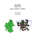
BD BOX version 2.2 user’s manual – bd rigid Pawel Zieliński Maciej Dlugosz 1 Copyright (C) 2010,2011,2012,2013,2014: University of Warsaw, Pawel Zieliński, Maciej Dlugosz This program is free software: you can redistribute it and/or modify it under the terms of the GNU General Public License as published by the Free Software Foundation, either version 3 of the License, or (at your option) any later version. This program is distributed in the hope that it will be useful, but WITHOUT ANY WARRANTY; without even the implied warranty of MERCHANTABILITY or FITNESS FOR A PARTICULAR PURPOSE. See the GNU General Public License for more details. You should have received a copy of the GNU General Public License along with this program. If not, see http://www.gnu.org/licenses/. Contact authors: Pawel Zieliński: [email protected] Maciej Dlugosz: [email protected] Work on the BD BOX package is supported by National Science Centre, grant number N N519 646640 2 BD BOX is a scalable Brownian dynamics package for UNIX/LINUX platforms. BD BOX is written in C and uses modern computer architectures and technologies: • MPI technology for distributed-memory architectures • OpenMP technology for shared-memory systems • NVIDIA CUDA framework for GPGPU • SSE vectorization for CPU Within the BD BOX framework macromolecules can be represented either with flexible bead models (the bd flex module of the BD BOX package) or as rigid bodies (the bd rigid module of the BD BOX package). When flexible models are employed, each molecule consists of a various number of spherical subunits (beads) connected with deformable bonds [1, 2]. Bonded interactions that result in deformations of planar and dihedral angles can be also modeled. Direct, nonbonded interactions between molecules are evaluated using pairwise functions describing screened electrostatics in dielectric media [3] with effective charges assigned to spherical subunits [4] and Lennard-Jones potential types. The far-field hydrodynamic effects are modeled using the configuration dependent Rotne-Prager-Yamakawa mobility tensor [5, 6, 7] or its Ewald-summed form in case of periodic systems [8, 9]. Equations of motions are propagated using either the Ermak-McCammon [10] scheme or the predictor-corrector IG-T algorithm by Iniesta and Garcia de la Torre [11]. Hydrodynamically correlated random displacements are generated either via the Cholesky factorization of the configuration-dependent mobility tensor matrix [10], using the TEA-HI approach proposed by Geyer and Winter [12, 13], or with an approach described by Ando and Skolnick [14] that utilizes Krylov subspaces. With BD BOX one can simulate flexible molecules in homogeneous flows [2] or external electric fields (direct, alternate or rotating fields). With BD BOX one can also simulate rigid bodies that are described with fully anisotropic diffusion tensors [15]. Molecules, treated as rigid bodies can be described either using a coarse-grained representation or with fully atomistic details. In the latter case, intermolecular interactions may include electrostatic, hydrophobic and Lennard-Jones potentials. External electric fields can also be applied to the simulated system. Hydrodynamic interactions between molecules modeled within the rigid-body framework are currently not supported. BD BOX simulations can be performed without or with boundaries; in the latter case the containing or periodic boundary conditions can be used. With BD BOX one can effectively simulate either single molecules or 3 multimolecular systems composed of large numbers of different species. For efficient simulations of dense systems we implemented algorithms preventing the overlapping of diffusing molecules [16, 17, 18]. This manual describes the usage of the bd rigid module of the BD BOX package. The bd flex module for BD simulations of flexible molecular models, is described separately. CONTENTS 4 Contents 1 Requirements 6 2 Installation 6 3 Rigid-body Brownian dynamics 9 3.1 Molecular Models . . . . . . . . . . . . . . . . . . . . . . . . . . . . . . . . . . . . . . . . . . . 9 3.2 Rigid-body Diffusion Tensor Matrix . . . . . . . . . . . . . . . . . . . . . . . . . . . . . . . . . . 10 3.3 Equations of Motions . . . . . . . . . . . . . . . . . . . . . . . . . . . . . . . . . . . . . . . . . 10 3.4 Rotations . . . . . . . . . . . . . . . . . . . . . . . . . . . . . . . . . . . . . . . . . . . . . . . 11 4 Intermolecular Interactions 12 4.1 Excluded Volume Interactions . . . . . . . . . . . . . . . . . . . . . . . . . . . . . . . . . . . . . 13 4.2 Hydrophobic Interactions . . . . . . . . . . . . . . . . . . . . . . . . . . . . . . . . . . . . . . . 13 4.3 4.2.1 FACTS Approach . . . . . . . . . . . . . . . . . . . . . . . . . . . . . . . . . . . . . . . 13 4.2.2 Primitive Approach . . . . . . . . . . . . . . . . . . . . . . . . . . . . . . . . . . . . . . 14 Electrostatic Interactions . . . . . . . . . . . . . . . . . . . . . . . . . . . . . . . . . . . . . . . 16 4.3.1 Screened Coulombic Interactions . . . . . . . . . . . . . . . . . . . . . . . . . . . . . . . 16 4.3.2 Polarization terms . . . . . . . . . . . . . . . . . . . . . . . . . . . . . . . . . . . . . . . 16 5 External Fields 17 5.1 Bounding Sphere . . . . . . . . . . . . . . . . . . . . . . . . . . . . . . . . . . . . . . . . . . . 17 5.2 Electric Field . . . . . . . . . . . . . . . . . . . . . . . . . . . . . . . . . . . . . . . . . . . . . . 17 6 Overlaps 18 7 Running Simulations with bd rigid 18 7.1 Structure File . . . . . . . . . . . . . . . . . . . . . . . . . . . . . . . . . . . . . . . . . . . . . 21 7.2 Tensor File . . . . . . . . . . . . . . . . . . . . . . . . . . . . . . . . . . . . . . . . . . . . . . . 22 7.3 External Coordinates File . . . . . . . . . . . . . . . . . . . . . . . . . . . . . . . . . . . . . . . 23 7.4 Simulation Control File . . . . . . . . . . . . . . . . . . . . . . . . . . . . . . . . . . . . . . . . 24 CONTENTS 8 Control File Keywords and Command Line Parameters 5 24 8.1 Input/Output Control . . . . . . . . . . . . . . . . . . . . . . . . . . . . . . . . . . . . . . . . . 25 8.2 Nonbonded Interactions . . . . . . . . . . . . . . . . . . . . . . . . . . . . . . . . . . . . . . . . 26 8.3 Boundaries . . . . . . . . . . . . . . . . . . . . . . . . . . . . . . . . . . . . . . . . . . . . . . . 28 8.4 External Electric Fields . . . . . . . . . . . . . . . . . . . . . . . . . . . . . . . . . . . . . . . . 28 8.5 Algorithms . . . . . . . . . . . . . . . . . . . . . . . . . . . . . . . . . . . . . . . . . . . . . . . 29 8.6 Physical Conditions . . . . . . . . . . . . . . . . . . . . . . . . . . . . . . . . . . . . . . . . . . 31 8.7 Devices Control . . . . . . . . . . . . . . . . . . . . . . . . . . . . . . . . . . . . . . . . . . . . 31 9 Tools 31 9.1 dmatrix . . . . . . . . . . . . . . . . . . . . . . . . . . . . . . . . . . . . . . . . . . . . . . . . . 32 9.2 orient mstr . . . . . . . . . . . . . . . . . . . . . . . . . . . . . . . . . . . . . . . . . . . . . . . 33 9.3 parsemolb . . . . . . . . . . . . . . . . . . . . . . . . . . . . . . . . . . . . . . . . . . . . . . . 34 9.4 molb2dcd . . . . . . . . . . . . . . . . . . . . . . . . . . . . . . . . . . . . . . . . . . . . . . . 34 9.5 sasa tool . . . . . . . . . . . . . . . . . . . . . . . . . . . . . . . . . . . . . . . . . . . . . . . . 35 9.6 charge optimizer . . . . . . . . . . . . . . . . . . . . . . . . . . . . . . . . . . . . . . . . . . . . 36 10 Examples distributed with BD BOX 38 11 Final Notes 38 1 REQUIREMENTS 1 6 Requirements The BD BOX package is distributed as source code. A UNIX/LINUX make tool is needed to build a working binary from the source code (see below). CPU versions of BD BOX binaries can be run either in a serial mode or in parallel, either on shared-memory machines using OpenMP and MPI libraries or on architectures with distributed memory using the MPI library. GPU versions of BD BOX binaries require the CUDA Toolkit (obtainable freely at http://developer.nvidia.com). Both CPU and GPU versions can be compiled with the support for either single or double-precision floating-point arithmetic. For the generation of random Gaussian numbers, BD BOX uses functions implemented in the GNU Scientific Library (GSL) (http://www.gnu.org/software/gsl) that are based on the Mersenne Twister algorithm of Matsumoto and Nishimura [19]. We also implemented a function that uses the standard system routine drand48() and the polar Box-Muller transformation [20]. A generic, sequential algorithm implemented in BD BOX for the Cholesky factorization, follows the choldc() subroutine described in [21]. However, it is better to compile BD BOX with the implemented support for the LAPACK (or SCALAPACK) library (http://www.netlib.org/lapack) that offers efficient, highly memory-optimized routines for the Cholesky factorization. LAPACK performs the vast amount of operations by exploiting BLAS. Machine-specific implementations of BLAS are available and such implementations can be crucial for the performance of BD BOX. The Cholesky factorization on GPU relays on the implemented support for the MAGMA dense linear algebra library (http://icl.cs.utk.edu/magma), which provides functionality of LAPACK. 2 Installation The configure shell script, written by GNU Autoconf is used to build the BD BOX binaries. After downloading and unpacking the compressed BD BOX archive: gzip -d bd box-ver.tar.gz tar -xvf bd box-ver.tar the user should execute the configure script from within the BD BOX directory: 2 INSTALLATION 7 cd ./bd box-ver ./configure configure takes instructions from Makefile.in and builds Makefile and some other files that work on the user’s system. We provide the INSTALL file and some other files (consult the README file in the bd box-ver directory) with flags and options that can be passed to the configure script to tune the compilation parameters on a particular system. Next, the: make command followed (optionally) by the: make install should be executed. As a result of the compilation process, two binaries: bd flex and bd rigid should be created, either within the bd box-ver/src directory, or in the directory passed by the user to the configure script (with the –prefix option). It is possible to prevent compilation of either one of binaries using –disable–flex or –disable-rigid flags. Tools distributed with the BD BOX package should be compiled separately. Their sources along with appropriate Makefiles ale located in bd box-ver/tools/tool name directories. Each tool can be compiled using the: make all command. 2 INSTALLATION Units charge: e length: Å time: ps temperature: K energy: kcal mol 8 3 RIGID-BODY BROWNIAN DYNAMICS 3 3.1 9 Rigid-body Brownian dynamics Molecular Models Within the BD BOX rigid-body framework molecules can be described either using a coarse-grained representation or with fully atomistic details. In both cases molecules are described as conglomerates of spherical subunits (i.e. atoms). Each kind of interaction that the molecule is involved in is assigned its own representation - for example for a given molecule a set of charged spheres can be used to evaluate electrostatic interactions and a different set (considering both positions and radii of spheres) can be used to evaluate excluded volume interactions with other molecules in the studied system (consult Figure 1 for the overall concept). Figure 1: Exemplary molecular models that are tractable within the BD BOX rigid-body framework. Models consist of spheres with radii defining excluded volume interactions (left). Point charges can be positioned inside molecules (their positions do not necessarily coincide with centers of spheres used to define excluded volume interactions (left)). Additionally, each charge can be assigned a non-zero radius (center). Charge radii are used to define the dielectric cavity occupied by the molecule. Positions and radii of spheres in the dielectric representation and in the excluded volume representation can be the same as for example in case of atomistically detailed molecular models - a molecule is then represented by a set of van der Waals spheres (atoms) with central point charges (right). 3 RIGID-BODY BROWNIAN DYNAMICS 3.2 10 Rigid-body Diffusion Tensor Matrix In dilute solutions, diffusional properties of molecules are determined by their size and shape, as well as by the temperature and viscosity of the solvent. The information required to characterize translational and rotational movements of quasi-rigid Brownian particles in dilute solutions is contained in their diffusion tensors. Singleparticle diffusion tensor, D , is represented by a symmetric, 6 × 6 matrix that consists of four 3 × 3 blocks. These blocks are related to translational (tt) and rotational diffusivities (rr ) and their couplings (rt,tr ) [15]: D= D tt D rt D tr D rr (1) Diffusion tensors of molecules can be obtained theoretically from rigid-body hydrodynamic calculations performed for detailed molecular models [22]. For a spherical particle the above matrix takes a diagonal form (isotropic diftt correspond to the translational diffusion coefficient of a sphere. Similarly, fusion) in which identical elements Dii rr give its rotational diffusion coefficient. For an arbitrarily-shaped object its average transidentical elements Dii D rr ), lational and rotational diffusion coefficients are defined, respectively, as: Dt = 31 T r D tt and Dr = 13 T r (D where the diffusion tensor (Equation 1) is evaluated in the molecule-fixed coordinate system with the origin located at the particle’s diffusion center, and whose axes coincide with the principal axes of the rotational diffusion tensor. 3.3 Equations of Motions The propagation scheme for an arbitrarily-shaped rigid body (that is described with a fully-anisotropic diffusion tensor) can be written in the molecule-fixed frame (again, by molecule-fixed frame we mean that the origin of the frame is assumed to be located at the diffusion center of the molecule and its axes coincide with the principal axes of diffusional rotations) as [10, 15]: ∆~x(∆t) = ∆t ~ + R(∆t) ~ DM kB T (2) where: D - the precomputed (and constant in the simulation) 6 × 6 diffusion tensor of the molecule evaluated in the molecule-fixed coordinate system with the origin located at the molecule’s diffusion center and axes coinciding 3 RIGID-BODY BROWNIAN DYNAMICS 11 with the principal axes of particle’s rotations (so that the submatrix D rr in Equation 1 is diagonal) ∆t - the time step ~ of the molecule, ~x = (~r, φ) ~ T ~x - the vector describing the position of the diffusion center (~r) and orientation (φ) ~ - the generalized force vector, resulting, for example, from interactions with other molecules or external M fields and having two components: the total force (F~ ) and the total torque (T~ ) referred to the molecule’s diffu~ = (F~ , T~ )T . sion center, M ~ R(∆t) - random displacement vector arising from the Brownian noise, with zero mean, and the variance-covariance given with: ~ ~ D ∆t < R(∆t) R(∆t) >= 2D (3) Random displacements of the particle can be computed via Cholesky decomposition of its diffusion tensor [10]. Brownian dynamics trajectory of an object in the laboratory frame is obtained by applying at each BD simulation step properly defined transformations - translations and rotations [15] - between the molecule-fixed and the laboratory coordinate frame. 3.4 Rotations The following matrix is utilized to perform rotational motions [23]: M11 M12 M13 M = M21 M22 M23 M31 M32 M33 where: 4 INTERMOLECULAR INTERACTIONS 12 M11 = (Ω2y + Ω2z )cosΩ + Ω2x Ω2 M12 = Ωx Ωy Ωz (1 − cosΩ) − sinΩ Ω2 Ω M13 = Ωy Ωx Ωz (1 − cosΩ) + sinΩ 2 Ω Ω M21 = Ωx Ωy Ωz (1 − cosΩ) + sinΩ 2 Ω Ω M22 = (Ω2x + Ω2z )cosΩ + Ω2y Ω2 M23 = Ωy Ωz Ωx (1 − cosΩ) − sinΩ Ω2 Ω M31 = Ωy Ωx Ωz (1 − cosΩ) − sinΩ 2 Ω Ω M32 = Ωy Ωz Ωx (1 − cosΩ) + sinΩ 2 Ω Ω M33 = (Ω2x + Ω2y )cosΩ + Ω2z Ω2 where the vector: ~ = {Ωx , Ωy , Ωz } Ω describes rotations around axes x, y, z of the molecule-fixed coordinate system, and: Ω= 4 q Ω2x + Ω2y + Ω2z Intermolecular Interactions ~ in Equation 2) are evaluated analytically based on derivatives of Forces and torques acting on molecules (M different potential functions that are described below. During simulations, intermolecular forces are evaluated within atom-based, spherical cutoffs, defined by the user. Minimum image convention is utilized in case of periodic systems. 4 INTERMOLECULAR INTERACTIONS 4.1 13 Excluded Volume Interactions Excluded volume interactions are modeled using pairwise terms of form: exc Eij q σi + σj n σi + σj m LJ LJ B − = α i j rij rij (4) where: n and m - non-negative integers i and j - indexes that run over atoms from different molecules σ - denotes an atomic radius LJ - the interaction well depth assigned to a given atom α and B - user-defined constants rij - the distance between the two interacting atoms values of n/m can be set to: 12/6, 12/0, 8/6, 8/0. 4.2 Hydrophobic Interactions Hydrophobic (i.e. nonpolar interactions) can be evaluated using one of the two solvent accessible surface based approaches implemented in BD BOX: either the FACTS model [24] or the model (that we will further refer to using the therm primitive) similar in the spirit to the approach described by Gabdoulline and Wade [25]. 4.2.1 FACTS Approach In the FACTS model, the nonpolar contribution to the free energy of solvation of a molecule is modeled in relation to the amount of its surface exposed to the solvent (SASA) [24]: E nonpolar =µ N X i=1 SASAi (5) 4 INTERMOLECULAR INTERACTIONS 14 where summation runs over all (N ) atoms of a molecule (or molecules), µ denotes the empirical surface tension parameter [26], and atomic SASAs are given with [24]: SASAi = co + Di = N X c1 1 + e−c2 (Di −c3 ) Vj j6=i rij Θij x̂ij | P Vj + N j6=i rij Θij PN Vj Θij + d1 | j6=i 1 + d2 N X (6) Vj j6=i rij Θij x̂ij | P Vj + N j6=i rij Θij PN Vj Θij | j6=i 1 (7) In the above equations Vj denotes the van der Waals volume of the j th atom, rij is the distance between atoms i and j, x̂ij is a unit vector pointing from the ith atom to the neighboring j th atom and Θij is a sigmoidal weighting function: Θij = 2 2 1 − rij , if rij ≤ Ri 0, if rij > Ri Ri (8) where Ri is a predefined radius of a sphere (i.e. cutoff) enclosing the ith atom. Parameters co , c1 , c2 , c3 , d1 and d2 that are derived by fitting to exact values of SASA [24] are defined in the PARAM22 CHARMM parameter set [27]. For all atoms values of Ri s are similar following the original parametrization of the FACTS model [24]. 4.2.2 Primitive Approach Each atom of a given molecule is assigned a constant SASA value computed in the absence of other molecules, SASAoi . The change in the SASA of a particular surface atom (i) of one molecule due to the proximity of surface atoms (j) of other molecules, SASAi , is computed as: SASAi = φSASAoi X fij (rij ) (9) j where fij (rij ) = b − (rij − σj ) f or a < rij − σj < b b−a fij (rij ) = 1 f or rij − σj < a (10) (11) 4 INTERMOLECULAR INTERACTIONS 15 fij (rij ) = 0 f or rij − σj > b (12) and φ is a user defined parameter, and σj is the van der Waals radius of the ith atom. Parameters a and b are also user defined (see Figure 2). Energy is computed as: Figure 2: Performance of the primitive approach. Total values of solvent accessible surfaces calculated for 1500 different relative configurations of two small proteins, with φ = 0.5, a = 1.3Å, and b = 6.4Å. All-atom protein models were used in calculations with atomic radii taken from the PARAM22 CHARMM parameter set [27]. Exact SASA values were calculated using APBS [28]. E nonpolar = µ N X i=1 (SASAoi − SASAi ) (13) 4 INTERMOLECULAR INTERACTIONS 4.3 4.3.1 16 Electrostatic Interactions Screened Coulombic Interactions The energy of the electrostatic interaction (screened by dissolved ions) between two charges qi and qj that belong to different molecules is computed as: Coulombic Eij =γ qi qj e−κrij rij (14) where: κ - the inverse of the Debye length rij - the distance between the two charges γ - the unit conversion factor (an user-defined parameter) - the dielectric constant of the solvent. 4.3.2 Polarization terms Polarization (desolvation) terms are evaluated between the charges of one molecule and the dielectric cavity of another molecule. Dielectric body of a molecule is treated as a conglomerate of spheres (i.e. atoms) [29]. Energy of the interaction between the ith charge (qi ) of one molecule with the j th dielectric sphere (radius σj ) of another molecule is computed as [30]: cavity Eij = γβ − p (1 + κrij )2 exp (−2κrij )(σj )3 (qi )2 4 (2 + p ) rij (15) where: γ - the unit conversion factor (an input parameter) β - the user-defined (an input parameter) constant that depends on ionic strength - it also takes into account the fact that atoms in the molecule overlap - the dielectric constant of the solvent p - the dielectric constant of a molecule rij - the distance between the ith charge of one molecule and j th atom of another molecule κ - the inverse of the Debye length. 5 EXTERNAL FIELDS 5 17 External Fields 5.1 Bounding Sphere A spherical surface, impenetrable for molecules, that encloses simulated system can be included in bd rigid simulations. The influence of such a containing sphere on the studied system is modeled by applying a central force of form: F~ = − A (Rsphere − r)n êr (16) where: Rsphere - the radius of a spherical surface n - a non-negative integer A - the amplitude of the force r - the distance between a diffusion center of a particular molecule and the system’s center of geometry The above force is applied to each of the studied molecules outside a predefined cutoff. 5.2 Electric Field It is possible to simulate with bd rigid the interactions of charged molecules with external electric fields: DC – direct current field ~ = Eo êE E (17) ~ = Eo cos (ωt)êE E (18) ~ = Eo (cos (ωt), sin (ωt), 0)êE E (19) AC – alternate current field RF – rotate field where êE = êx or êE = êy or êE = êz , Eo is the magnitude of the external field and ω its frequency. Except for the rotate field, all other fields act along the space fixed direction. 6 OVERLAPS 6 18 Overlaps The presence of the Gaussian random displacement vector in the BD integration scheme (Equation 2) may lead to nonphysical overlaps between molecules. Overlaps occur when the distance between two atoms that belong to different molecules is smaller than the sum of excluded volume radii of these atoms. bd rigid can check whether a particular simulation step leads to an overlap. Next, positions of molecules are corrected to remove all cases of overlaps. This can be done in one of the four ways. One option is that the current step of the simulation is rejected, original positions of all molecules are restored and a new step is attempted with a different random vector, until there are no cases of overlaps. The second option is similar to the first, however, each of the subsequent attempts is made with a smaller time step. After successful removal of all overlaps, the time step is restored to its initial value. As a third option, we also implemented an iterative procedure that removes overlaps between atoms via translations and rotations around diffusion centers of colliding molecules (∆~xcorr ) resulting from pseudo-forces ~ corr ): acting along the line connecting centers of overlapping atoms (M D M~corr ∆~xcorr (∆t) = ξD (20) where: ξ - the scaling factor D - the diffusion tensor. Each pair of overlapping atoms is treated separately. Translations and rotations of molecules are performed until there are no overlaps in the system. The fourth option is similar in the spirit to the third one but overlaps between two different molecules are evaluated simultaneously and all pairs of overlapping atoms from a given molecule pair are considered in order to determine the directions of correcting forces. 7 Running Simulations with bd rigid Various input files are needed to perform BD simulations with the bd rigid module of the BD BOX package (Figure 3). 7 RUNNING SIMULATIONS WITH BD RIGID 19 Figure 3: Schematics of the BD BOX bd rigid module Structure files (*.mstr ) contain definitions of molecular models that are used to represent different types of molecules to be simulated. A separate *.mstr file is required for each kind of a molecule that is present in the simulated system (for example, when monodisperse system is to be simulated, a single structure file will suffice); the number of molecules of each kind in the system is specified by the user in the *.prm file. Diffusion tensor files (*.dt) contain definition of diffusion tensors of simulated molecules. A separate *.dt file is required for each kind of a molecule that is present in the simulated system. Simulation parameters are stored in the text control file (*.prm) (Figure 3). These include for example the type of the propagation algorithm and its time step, temperature, ionic strength, definition of boundaries, values of cutoffs for intermolecular interactions, specifications of the output (names and types of files, write frequency), path to the input structure and diffusion tensor files, numbers of molecules of different types in the simulated system, and many others. 7 RUNNING SIMULATIONS WITH BD RIGID 20 While molecules are usually placed by the program at random positions and with random orientations inside the primary simulation cell, it is also possible to define initial positions and orientations of all objects in the simulated system using a text-formatted file (Figure 3). The output from bd rigid consists of a few files (Figure 3). The output file (*.out/*.err ) contains the track of the BD run, error messages (if any) and debugging information. Another file, in the PQR format (*.pqr ), contains the definition of the molecular system under study - it can be used to verify the starting configuration of molecules and also (together with a trajectory file) to visualize results. The trajectory file, either in the binary DCD or binary MOLB format (*.dcd/*.molb) describes the timedependent behavior of the studied system. MOLB trajectory contains only translations and rotations that are needed to perform transformations from the molecule-fixed to the laboratory frame, while DCD files contain Cartesian coordinates of atoms of all molecules in the simulated system in the laboratory frame. The energy file (*.enr ) registers different contributions to the total energy of the system during a simulation. The binary restart file (*.rst) contains all the information needed to continue an interrupted BD run. All files are periodically updated during a BD run with frequencies defined by the user. Having prepared all the necessary files, the user may run the simulation with the command: bd rigid file.prm It is also possible not to use the control file at all or to override all options specified in the control file by using command line parameters that correspond to appropriate control file keywords: bd rigid −−parameter=value or bd rigid file.prm −−parameter=value 7 RUNNING SIMULATIONS WITH BD RIGID 7.1 21 Structure File Structure file contains representations of a molecule that are used in evaluation of intermolecular interactions. In general, the structure file adheres to the following format: TAG list of properties Currently, two tags are recognized: Q and LJ. Lines that begin with the tag Q define dielectric/electrostatic model of a molecule. Molecule is composed of dielectric spheres with central discrete charges. Lines that begin with the tag Q should be formatted as follows: Q x1 y1 z1 charge1 radius1 ................ Q xi yi zi chargei radiusi ................ Q xN yN zN chargeN radiusN where x, y, z denote Cartesian coordinates of a dielectric sphere in the molecular frame, charge denotes its central charge and radius denotes its radius. Molecular representation specified with Q tags is used in evaluation of electrostatic interactions (Coulombic and desolvation terms, equations 14 and 15). Molecular representation specified with LJ tags is used in evaluation of collisions, excluded volume and hydrophobic interactions. Lines that begin with the LJ tag should be formatted as follows: LJ x1 y1 z1 radius1 1 d11 d21 c01 c11 c21 c31 µ1 SASAo1 ................... LJ xj yj zj radiusj j d1j d2j c0j c1j c2j c3j µj SASAoj ................... LJ xM yM zM radiusM M d1M d2M c0M c1M c2M c3M µM SASAoM 7 RUNNING SIMULATIONS WITH BD RIGID 22 where x, y, z denote Cartesian coordinates of spheres in the molecular frame, radius denotes radius used in evaluations of excluded volume and hydrophobic interactions, is the well depth of excluded volume interactions, parameters d and c are for the FACTS model (equations 6, 7), SASAo denotes the solvent accessible surface area of a given sphere in the model (Equation 9) and µ (Equations 5, 13) denotes the surface tension parameter. Molecular representations given with tags Q and LJ can differ both in the number of spheres (atoms) and their positions. We supply a tool (orient mstr, see below) that can be used to transform (rotate and translate) molecular coordinates (given either as a *.mstr, *.pdb or *.pqr files to the molecular frame that coincides with the main axes of diffusional rotations with the origin located at the diffusion center of a molecule. 7.2 Tensor File Diffusion tensor files (*.dt) (a separate file is needed for each type of a molecule that is present in the simulated system) contain elements of the diffusion tensor matrix in the plain text format. Elements of D are given in *.dt files in the following order: tt D tt D tt D11 12 13 tr D tr D tr D11 12 13 tt D tt D tt D21 22 23 tr D tr D tr D21 22 23 tt D tt D tt D31 32 33 tr D tr D tr D31 32 33 rt D rt D rt D11 12 13 rr D rr D rr D11 12 13 rt D rt D rt D21 22 23 rr D rr D rr D21 22 23 rt D rt D rt D31 32 33 rr D rr D rr D31 32 33 tr/rt tt are Å2 · ps−1 , units of D where units of Dij ij rr are ps−1 . Elements of D are Å·ps−1 and units of Dij should be given in the molecule-fixed frame with origin located at the diffusion center of a molecule and axes coinciding with principal axes of rotations. We provide a tool (dmatrix, see below) that can be used to compute the diffusion tensor matrix of a molecule either based on the appropriate PDB file or a plain text file containing 7 RUNNING SIMULATIONS WITH BD RIGID 23 its coarse-grained representation. 7.3 External Coordinates File Initial coordinates of objects in the studied system (in the laboratory frame) can be specified by the user in an external text file, which should adhere to the following format: (1) (1) vx vy (1) vz (1) (1) (1) Ωx Ωy Ωz ........... (i) (i) (i) (i) (i) (i) vx vy vz Ωx Ωy Ωz .......... (N ) vx (N ) vy (N ) vz (N ) Ωx (N ) Ωy (N ) Ωz where i runs over N molecules (ordering of molecules results from parameters defined in the *.prm file see below); the vector: ~v = {vx , vy , vz } describes translations that are needed to translate the diffusion center of a molecule to its initial position in the laboratory frame, and the vector: ~ = {Ωx , Ωy , Ωz } Ω describes rotations that are needed to orient the molecule in the laboratory frame. Ω= q Ω2x + Ω2y + Ω2z The rotation matrix is defined as [23]: M11 M12 M13 M = M21 M22 M23 M31 M32 M33 8 CONTROL FILE KEYWORDS AND COMMAND LINE PARAMETERS 24 where: M11 = M12 = Ωx Ωy Ωz (1 − cosΩ) − sinΩ Ω2 Ω M13 = Ωy Ωx Ωz (1 − cosΩ) + sinΩ 2 Ω Ω M21 = Ωx Ωy Ωz (1 − cosΩ) + sinΩ 2 Ω Ω M22 = (Ω2x + Ω2z )cosΩ + Ω2y Ω2 M23 = Ωy Ωz Ωx (1 − cosΩ) − sinΩ Ω2 Ω M31 = Ωy Ωx Ωz (1 − cosΩ) − sinΩ 2 Ω Ω M32 = Ωy Ωz Ωx (1 − cosΩ) + sinΩ 2 Ω Ω M33 = 7.4 (Ω2y + Ω2z )cosΩ + Ω2x Ω2 (Ω2x + Ω2y )cosΩ + Ω2z Ω2 Simulation Control File Control file is based on a number of keywords that allow the user to specify simulations conditions. Only these lines in the control file that begin with a particular keyword are recognized by the program. Each line of the *.prm file should contain only one keyword and its value: keyword value The complete list of available keywords is given in the next section. 8 Control File Keywords and Command Line Parameters Below, a complete list of recognized keywords and their possible values, is given. Values of all keywords relevant to a simulation must be specified by the user - default values that are given below are these at which program variables are initialized and they are not always meaningful. 8 CONTROL FILE KEYWORDS AND COMMAND LINE PARAMETERS 8.1 25 Input/Output Control out filename string - text file containing diagnostic informations regarding the current bd rigid run (output) dcd filename string - DCD-formatted binary trajectory file, default: NULL string (output) save dcd freq integer - frequency (number of steps) for writing to the DCD trajectory, default: 1 pqr filename string - PQR-formatted file, containing the startup configuration of the simulated system, default: NULL string (output) rep string - this keyword is used to define which molecular representation from the *.mstr file (tags Q and LJ) should be written to the PQR-formatted file, possible options are lj (Lennard-Jones spheres defined with the LJ tags) or elec (charges, defined with the Q tags); default lj molb filename string - binary trajectory file (*.molb), default: NULL string (output) save molb freq integer - frequency (number of steps) for writing to the *.molb trajectory, default: 1 enr filename string - plain text energy file, default: NULL string (output) save enr freq integer - frequency (number of steps) for writing to the energy file, default: 1 rst filename string - binary restart file, default: NULL string (output) save rst freq integer - frequency (number of steps) for writing to the binary restart file, default: 1 ext coor file string - an optional plain text file describing an user-defined configuration of the simulated system, default: NULL string (input) 8 CONTROL FILE KEYWORDS AND COMMAND LINE PARAMETERS 26 restart string - this keyword indicates that a continuation run should be performed, using the string restart file, default: NULL string (input); restarts should be specified using command line parameters object string integer - the name of the object (molecule) to be simulated and the number of objects of this kind in the system - the program will look for appropriate string.mstr and string.dt files; multiple object lines can be present in the parameter file - their order determines the ordering of molecules in all output files as well as the order of objects in the external coordinate file defined with the ext coor file key benchmark string - whether to benchmark evaluation of forces (yes no), default: no, 8.2 Nonbonded Interactions elec string - whether to evaluate electrostatic (screened Coulomb) interactions, yes/no, default: yes elec desolv string - whether to evaluate desolvation (cavity) forces, yes/no, default: yes hdb surf string - whether to evaluate non-polar (hydrophobic) interactions, none/primitive/facts, default: none elec cutoff float - cutoff for electrostatic interactions (also cavity terms), default: 0 hdb cutoff float - cutoff for nonpolar interactions evaluated with the FACTS model (Ri in Equation 8),default: 10.0 hdb a float - inner cutoff for nonpolar interactions evaluated with the primitive model (a in Equation 10), default: 3.1 hdb b float - outer cutoff for nonpolar interactions evaluated with the primitive model (a in Equation 10), default: 4.35 hdb phi float - scaling factor for nopolar interactions evaluated with the primitive approach, default: 0.5 8 CONTROL FILE KEYWORDS AND COMMAND LINE PARAMETERS 27 lj cutoff float - cutoff for Lennard-Jones interactions, default: 10.0 ; setting this parameter to -1 results in 1 cutoffs defined for each pair of atoms as 2 6 (Ri + Rj ) (useful in case of the 12/6 form of the L-J potential) lj repul float - repulsive term in the Lennard-Jones potential, (Equation 4, r−lj repul ), possible values 8, 12, default: 12 lj attract float - attractive term in the Lennard-Jones potential, (Equation 4, r−lj attract ), possible values: 0, 6, default: 6 repul B float - the magnitude of the repulsive part in the Lennard-Jones potential (Equation 4), default: 1 probe radius float - radius of the spherical probe used to determine surface atoms - during simulations collisions are evaluated between surface atoms, default: 1.4 srf ratio float - value used to determine whether an atom is buried or belong to the surface of a molecule, i.e. if for a given atom the ratio surf aceburied /surf acetotal is smaller than srf ratio the atom belongs to the surface of the molecule, default: 0.9 points per sphere integer - number of points used to describe the surface of an atom, default: 1000 gamma float - unit conversion factor for electrostatic interactions (Equation 14 and 15), default (conversion to kcal mol ): 331.842 alpha float - scaling factor for Lennard-Jones interactions (Equation 4), default: 4.0 beta float - scaling factor for desolvation (cavity) forces (Equation 14 and 15), default: 1.0 8 CONTROL FILE KEYWORDS AND COMMAND LINE PARAMETERS 8.3 28 Boundaries bc string - specifies boundary conditions, possible values are none - an infinite system, pbc - periodic boundary conditions, sphere - an impenetrable sphere xbox float - the primary simulation cell, size in the x direction, default: 0.0 ybox float - the primary simulation cell, size in the y direction, default: 0.0 zbox float - the primary simulation cell, size in the z direction, default: 0.0 sphere radius float - the radius of an impenetrable sphere enclosing the simulated system, default: 0.0 sboundary string - whether to use the bounding sphere potential, default: no (another possibility yes). Note that this keyword has nothing to do with the bc keyword; if bc sphere is used molecules are not allow to cross a spherical surface around the studied system but no potential is used for that, rather BD moves leading outside the spherical surface are simply rejected an repeated with different random vectors sboundary A float - the magnitude of the bounding sphere force (Equation 16), default: 0.0 sboundary n integer - the power of the radial distance dependence of the bounding sphere force (Equation 16), default: 0 sboundary cutoff float - the bounding sphere force is applied outside this cutoff radius (Equation 16), default: 0.0 8.4 External Electric Fields E ext string - whether to switch on/off the external electric field, yes/no, default: no 8 CONTROL FILE KEYWORDS AND COMMAND LINE PARAMETERS 29 E magn float - the magnitude of the external electric field, default: 0.0 E type string - a choice between different types of the electric field, possible values are AC, DC or RF, default: DC E freq float - the frequency (where applicable) of the external electric field (units h i 1 ps ), default: 0.0 E dir1 string - the direction of the external electric field, x, y or z, default: x E dir2 string - the second direction of the external electric field (RF), x, y or z, default: y E factor float - the unit conversion factor for the external electric field (to 8.5 kcal −1 −1 mol ·e Å ), default: 1.0 Algorithms bd algorithm string - this keyword defines the algorithm that is used to generate the BD trajectory of the studied system, possible values are ermak const (the time step is constant during the simulation) or ermak var (variable time step is used in order to prevent overlaps between simulated objects) bd steps integer - the number of BD simulation steps dt float - time step min dt float - minimal possible value of the time step when the variable time step algorithm is used rand seed integer - seed for the random number generator move attempts integer - the maximal number of attempts that are made by the program to remove overlaps in the system, in each attempt a BD step that leads to an overlap is repeated with a different random vector (Equation 3) 8 CONTROL FILE KEYWORDS AND COMMAND LINE PARAMETERS 30 pos iter integer - maximal number of iterations that are performed by the program to position and orient objects in the simulation cell at the begining of the BD run pos min integer - the minimal allowed surface-to-surface distance between objects in the simulation cell at the begining of the BD run check overlaps string - whether to check if there are overlapping objects in the simulated system whose positions need to be corrected yes/no overlaps string - defines the algorithm that is applied to look for the overlaps in the system, either trees (for a hierarchical algorithm) or direct (for a brute force algorithm) overlaps removal string - defines the method that is applied to remove overlaps in the system: none (if the check overlaps keyword is set to yes the program will repeat all steps that lead to overlaps with different random vectors), atom - overlaps will be corrected iteratively by applying appropriate forces and torques - each pair of overlapping atoms is evaluated separately, molecule - overlaps will be corrected iteratively by applying forces and torques and evaluating all pairs of overlapping atoms within a given molecules pair simultaneously nb list string - defines a method that is used to evaluate nonbonded interactions; brute - brute force method, spatial - a method similar in the spirit to the cell-linked lists algorithm, however, without explicit creation of nonbonded lists, verlet - Verlet lists algorithm with a twin-range cutoff verlet roff float - defines the value of the outer cutoff in the twin-range cutoff Verlet algorithm, i.e. the outer cutoff is computed as a cutoff increased by verlet roff verlet count integer - Verlet lists will be refreshed during a simulation every verlet count steps dm alg float - defines the method used to perform thread decomposition (in case of parallel runs), either atomdec 9 TOOLS 31 (decomposition is based on the indexes of atoms) or spatialdec (decomposition is performed based on Cartesian coordinates of atoms) 8.6 Physical Conditions T float - temperature, default: 298.15 kappa float - the inverse of the Debye length, default: 0.1 eps float - solvent dielectric constant, default: 78.54 epsin float - solute dielectric constant, default: 1 8.7 Devices Control cuda devices integer integer - CUDA devices to be used, their numbers followed by system identifiers cuda blockinteger - dimension of the thread block - relevant in case of CUDA devices with the compute capability smaller than 2.0 9 Tools We provide a set of tools that can be used to prepare input files necessary to perform BD simulations with the BD BOX bd rigid module. These are described below. 9 TOOLS 9.1 32 dmatrix This utility can be used to compute the rigid-body diffusion tensor of a molecule. In case of an atomistic model of a molecule coordinates are read from a PDB-formatted file. However, if the user needs to compute the diffusion tensor of a coarse-grained molecular model, its coordinates should be specified directly in the text input file. dmatrix requires an input file input.txt (the name of the file should not be changed) that adheres to the following format: input.txt - computations are to be performed for a molecule whose coordinates are stored in a PDB-formatted file: ————————————————————comment - single line containing comments (can be left empty) 1 - coordinates of a molecule are stored in the PDB file name of the appropriate PDB file - name of the PDB file with coordinates of a molecule viscosity temperature - viscosity of the solvent (Poisse) and temperature (K) solvent radius - radius of solvent molecules (typically set to 1.4Å - water) ————————————————————- input.txt - computations are to be performed for a coarse-grained model: ————————————————————comment - single line containing comments (can be left empty) 0 - computations are to be performed for a coarse-grained model number of beads in a model - number of spherical subunits (atoms) in a model x y z radius - coordinates of a spherical subunit and its radius x y z radius x y z radius ... viscosity temperature - viscosity of the solvent (Poisse) and temperature (K) solvent radius - radius of solvent molecules (typically set to 0.0Å in case of coarse-grained models) ————————————————————- 9 TOOLS 33 To run computations, the user should simply execute the dmatrix command from within the directory where the input.txt file is located. As a result, three text files should be created: output.txt - details of computations and debugging information tensor.txt - 6 × 6 diffusion tensor matrix transformations.txt - transformations (translations and rotations) that should be performed to orient the molecule along main axes of the rotational diffusion tensor, with the origin located at the diffusion centre. This file can be fed to the orient mstr utility. NOTE: when computations are performed for a coarse-grained model, overlaps between beads defined in the input.txt file are possible only if all beads in a model are of the same size 9.2 orient mstr Tool for orienting molecule in the molecular frame (with axes coinciding with the principal axes of diffusional rotations). Usage: orient mstr transformations structure where: transformations - file resulting from the execution of the dmatrix tool structure - file containing coordinates of a molecule to be transformed (PDB/PQR/MSTR files are supported) Results of the orient mstr execution - transformed coordinates of a molecule formatted according to the format of the input structure file - are printed to the standard output. 9 TOOLS 9.3 34 parsemolb Tool for converting binary *.molb files to text Usage: parsemolb file index precision where: file - name of the *.molb file to be converted index - index of a molecule whose coordinates are to be extracted (numbering of molecules starts with 0) precision - either float or double Output is printed to the standard output using the following format: time vx vy vz o(1) .... o(9) where time denotes current time, vx , vy , vz are components of the translation vector (from the molecule-fixed to the laboratory frame) and o(1) ... o(9) are components of the rotation matrix. Current position of a given molecule in the laboratory frame can be obtained by applying rotations and then translations to the input structure of a molecule. 9.4 molb2dcd Tool for converting binary *.molb trajectory files to binary *.dcd files. Usage: molb2dcd input type precision name where: input - text input file type - either all or separate - coordinates of molecules are either stored in a single file or separate *.dcd files are created for each molecule precision - either double or float name - input *.molb file 9 TOOLS 35 The text input file is used to specify molecules for which DCD trajectory will be created, it contains names of PDB files and indexes of molecules of interest in the source *.molb file. Indexes can be given as a list or as a range. An exemplary text input file is given below. exemplary text input file for the molb2dcd utility ———————————————————— name0.pdb 0 name1.pdb 1-10 name2.pdb 11 12 13 14 15 name3.pdb 16 ———————————————————— 9.5 sasa tool This small utility program can be used to compute atomic SASA’s using atomic coordinates and radii of atoms provided by the user in the PQR-formatted input file. Usage: sasa tool input output N radius where: input - input *.pqr file output - output file, plain text N - number of points used to describe the surface of an atom radius - radius of the solvent probe 9 TOOLS 9.6 36 charge optimizer Utility program that can be used to derive a set of effective charges. Effective charges positioned initially at heavy atoms of the molecule are derived by fitting the electrostatic potential resulting from the Debye-Hückel approximation to the external molecular potential obtained as a numerical solution of the Poisson-Boltzmann equation (see [31] for details). The total number of effective charges is optimized upon the execution of charge optimizer. Fitting of effective charges can be performed in various regions around the molecule: the whole space around the molecule, spherical layer centered on the molecule, or the molecular skin defined by inflating van der Waals radii of molecule’s atoms (see Figure 4). Execution of the program is controlled via keywords given in the plain text parameter file. Usage: charge optimizer file.prm and the following keywords can be specified in the parameter file (in the keyword value manner): gamma float - unit conversion factor, the default value of 331.842 results in electrostatic potentials evaluated in units of kcal mol·e eps float - dielectric constant of the solvent kappa float - the inverse of the Debye length, default: 0.1 Å−1 dxfile string - DX-formatted file with the electrostatic potential of the molecule obtained by solving the linear Poisson-Boltzmann equation, input outsourcedx string - DX-formatted file with the input electrostic potential (scaled by ext phi scale, see below) that can be used for debuging and visualization purposes, output ext phi scale float - factor for scaling (multiplication) values of the input electrostatic potential (can be used to convert units), default value: 0.5922 (scaling from kT298K to kcal mol ) skip points integer - every skip points point of the input grid (in each direction, x, y, z) will be taken into account upon evaluation of electrostatic potential, default: 1 - all points are taken into account pqrfile string - input, PQR-formatted file containing the definition of the evaluated molecule outdx string - DX-formatted file with the electrostatic potential generated by the derived effective charges, output 9 TOOLS 37 outpqr - PQR-formatted output file with effective charges tol float - goodness of electrostatic charges fit, this keyword is used to define the stop condition for the program - value of 1.0 means perfect fit (sensible values of effective charges are typically obtained for tol in the range of 0.85 to 1.0), default value: 0.9995 penalty float - this variable is used to prevent the effective charges to have unphysical (extremely large) magnitudes, typically values below 0.01 should used, default:0.001 step attempts integer - number of attempts made by the prgram to reduce the number of effective charges, default: 1000; initially effective charges are positioned at heavy atoms - if possible this number is subsequently reduced while preserving the accuracy specified with the tol parameter seed integer - seed for the random number generator, 31415 omega string - defines the region where the fitting is performed, possible values are full, sphere, skin omega low float - lower boundary of the fitting region, relevant for all values of the omega keyword omega high float - upper boundary of the fitting region, relevant only for omega values skin and sphere out filename string - plain text log file, default: err.log Figure 4: Possible definitions of the region outside the molecule where its electrostatic potential is fitted upon evaluation of effective charges. When the omega parameter is assigned value skin, electrostatic potential is fitted in the volume bounded by surfaces obtained by inflating van der Waals surface of the molecule by omega low and omega high (left). When omega is set to full the upper bondary of the volume results from the definition of the input electrostatic grid (center). Setting omega to sphere results in a volume of spherical layer between surfaces of spheres of radii omega low and omega high, respectively (right). 10 EXAMPLES DISTRIBUTED WITH BD BOX 38 Examples distributed with BD BOX 10 Below, we present a list of examples that are distributed along with the BD BOX source code. Examples are located in examples/rigid/name directories. HEWL A single hen egg white lysozyme molecule. All-atom model. SPHERES Periodic box with hard spheres at volume fraction of 30%. QSPHERES Periodic box with oppositely charged spheres. HEWL pH3 100mM 420 molecules of hen egg white lysozyme at volume fraction of 10%. Charges assigned at pH 3 and 100mM ionic strength. 11 Final Notes We did our best to ensure that the BD BOX code is bug-free. We have tested implemented features using rather simple and thus predictable models (such as single spheres, dumbbells, chains) but also more elaborate models of proteins. Properties of these models derived from BD simulations (such as for example translational and rotational diffusion coefficients at different conditions of temperature and viscosity, chains end-to-end distances and their radii of gyration) were validated using theoretical/analytical predictions and available literature data. Additionally, we have also cross-examined BD BOX using various hardware platforms. We invite users to send comments and questions regarding their own applications of BD BOX. Reports on possible bugs are also welcomed. References [1] K Kremer and G S Grest. Dynamics of entangled linear polymer melts: A molecular-dynamics simulation. J Chem Phys, 92:5057–5087, 1990. REFERENCES 39 [2] J G de la Torre, J G H Cifre, A Ortega, R R Schmidt, M X Fernandes, H E P Sánchez, and R Pamies. Simuflex: algorithms and tools for simulation of the conformation and dynamics of flexible molecules and nanoparticles in dilute solution. J Chem Theory Comput, 5:2606–2618, 2009. [3] G M Bell, S Levine, and McCartney L N. Approximate methods of determining the double-layer free energy of interaction between two charged colloidal spheres. J of Colloid Int Sci, 33:335–359, 1970. [4] M Aubouy, E Trizac, and L Bocquet. Effective charge versus bare charge: an analytical estimate for colloids in the infinite dilution limit. J Phys A: Math Gen, 36:58355840, 2003. [5] J Rotne and S Prager. Variational treatment of hydrodynamic interaction in polymers. J Chem Phys, 50:4831–4838, 1969. [6] H Yamakawa. Transport properties of polymer chains in dilute solution: hydrodynamic interaction. J Chem Phys, 53:436–444, 1970. [7] J G de la Torre and V A Bloomfield. Hydrodynamic properties of macromolecular complexes. i. translation. Biopolymers, 16:1747 – 1763, 1977. [8] E R Smith, I K Snook, and W van Megen. Hydrodynamic interactions in brownian dynamics simulations. i. periodic boundary conditions for computer simulations. Physica A, 143:441–467, 1987. [9] C W J Beenakker. Ewald sum of the rotne-prager tensor. J Chem Phys, 85:1581–1582, 1986. [10] D L Ermak and J A McCammon. Brownian dynamics with hydrodynamic interactions. J Chem Phys, 69:1352–1360, 1978. [11] A Iniesta and J G de la Torre. A second order algorithm for the simulation of the brownian dynamics of macromolecular models. J. Chem. Phys., 92:2015–2019, 1990. [12] U Winter and T Geyer. Coarse grained simulations of a small peptide: Effects of finite damping and hydrodynamic interactions. J Chem Phys, 131:104102–104107, 2009. [13] T Geyer and U Winter. An o(n2) approximation for hydrodynamic interactions in brownian dynamics simulations. J Chem Phys, 130:114905–114913, 2009. REFERENCES 40 [14] T Ando and J Skolnick. Krylov subspace mthods for computing hydrodynamic interactions in Brownian dynamics simulations. J. Chem. Phys., 137:064106, 2012. [15] M X Fernandes and J G de la Torre. Brownian dynamics simulations of rigid particles of arbitrary shape in external fields. Biophys J, 83:3039–3048, 2002. [16] P Strating. Brownian dynamics simulations of hard-sphere suspension. Phys Rev E, 59:2157–2187, 1999. [17] J Sun and H Weinstein. Toward realistic modeling of dynamic processes in cell signaling: Quantification of macromolecular crowding effects. J Chem Phys, 127:155105–155115, 2007. [18] S R McGuffee and A H Elcock. Atomically detailed simulations of concentrated protein solutions: the effects of salt, ph, point mutations and protein concentration in simulations of 1000-molecule systems. J Am Chem Soc, 128:12098, 2006. [19] M Matsumoto and T Nishimura. Mersenne twister: A 623-dimensionally equidistributed uniform pseudorandom number generator. ACM Transactions on Modeling and Computer Simulation, 8:330, 1998. [20] G E P Box and M E Muller. A note on the generation of random normal deviates. Annals Math Stat, 29:610–611, 1958. [21] W Press, B Flannery, S Teukolsky, and W Vetterling. Numerical recipes in C: the art of scientific computing. Cambridge University Press, 1992. [22] B Carrasco and J G de la Torre. Hydrodynamic properties of rigid particles: comparison of different modeling and computational procedures. Biophys J, 76:3044–3057, 1999. [23] D A Beard and Schlick T. Unbiased rotational moves for rigid-body dynamics. Biophys. J., 85:2973–2976, 2003. [24] U Haberthür and A C Caflisch. Facts: Fast analytical continuum treatment of solvation. J. Comput. Chem., 29:701–715, 2008. [25] R R Gabdoulline and R C Wade. On the contributions of diffusion and thermal activation to electron transfer between phormidium laminosum plastocyanin and cytochrome f: Brownian dynamics simulations with explicit modeling of nonpolar desolvation interactions and electron transfer events. J Am Chem Soc, 131:9230–9238, 2009. REFERENCES 41 [26] B Roux and T Simonson. Implicit solvent models. Biophys. Chem., 78:1–20, 1999. [27] A D MacKerell Jr., D Bashford, M Bellott, R L Dunbrack Jr., J D Evanseck, M J Field, S Fischer, J Gao, H Guo, S Ha, D Joseph-McCarthy, L Kuchnir, K Kuczera, F T K Lau, C Mattos, S Michnick, T Ngo, D T Nguyen, B Prodhom, W E Reiher III, B Roux, M Schlenkrich, J C Smith, R Stote, J Straub, M Watanabe, J Wiórkiewicz-Kuczera, D Yin, and M Karplus. All-atom empirical potential for molecular modeling and dynamics studies of proteins. J. Phys. Chem. B, 102:3586–3616, 1998. [28] N A Baker, D Sept, S Joseph, M J Holst, and J A McCammon. Electrostatics of nanosystems: application to microtubules and the ribosome. Proc Natl. Acad Sci USA, 98:10037–10041, 2001. [29] R R Gabdoulline and R C Wade. Effective charges for macromolecules in solvent. J Phys Chem, 100:3868– 3878, 1996. [30] X Li, Y Levin, and M E Fisher. Cavity forces and criticality in electrolytes. Europhys. Lett., 26:683–688, 1994. [31] M Dlugosz and Antosiewicz J. Anisotropic diffusion effects on the barnase-barstar encounter kinetics. J. Chem. Theory Comput., 9:1667–1677, 2013.